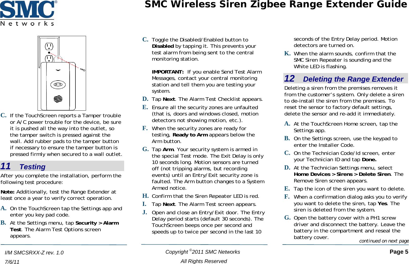
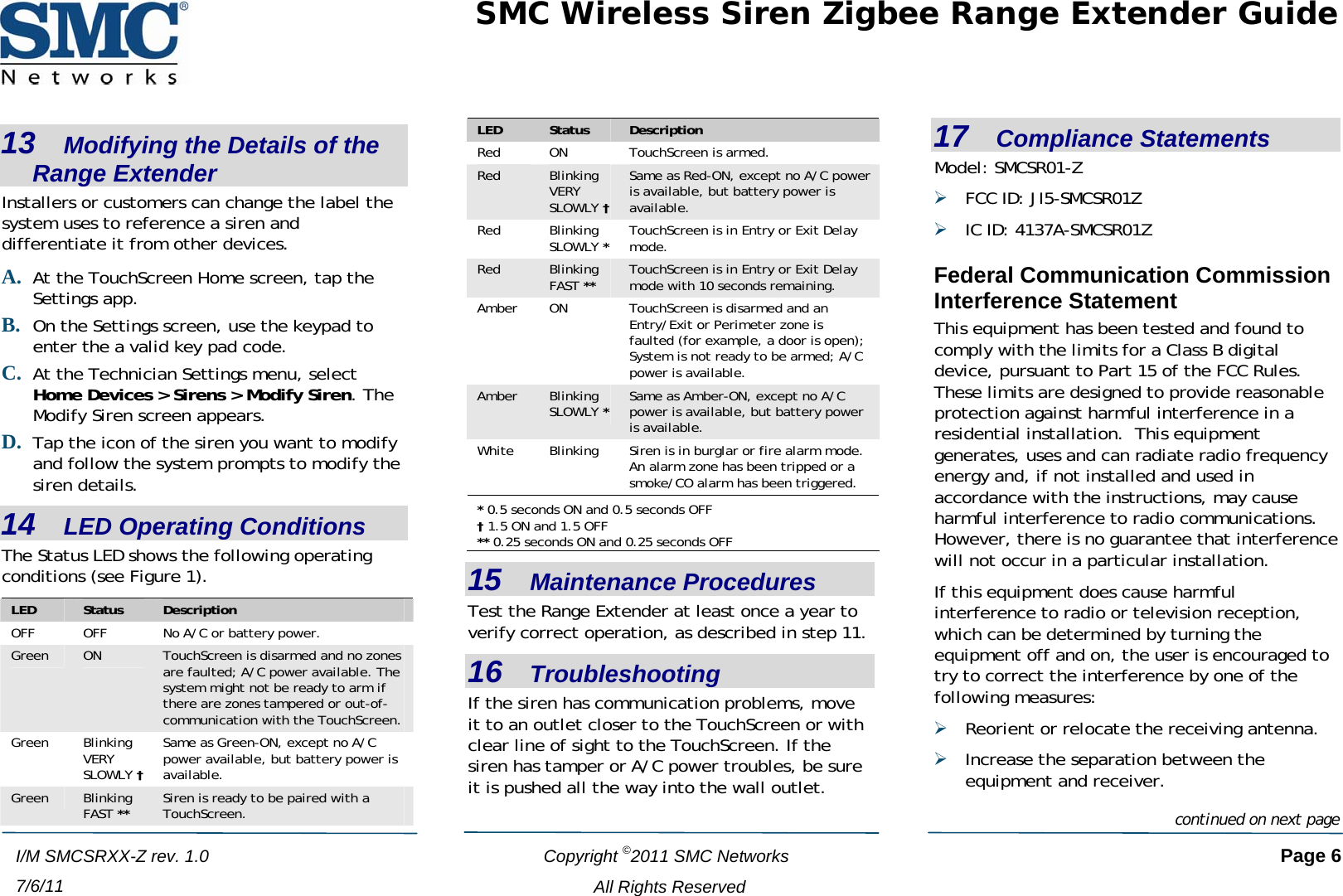
SMC Networks SMCSR01Z Home Siren Repeator User Manual SMC Wireless Siren Zigbee Range Extender Guide

SMC Networks Inc Home Siren Repeator SMC Wireless Siren Zigbee Range Extender Guide

UserMan_JI5-SMCSR01Z

 SMC Wireless Siren Zigbee Range Extender Guide  Copyright ©2011 SMC Networks   Page 1 All Rights Reserved  I/M SMCSRXX-Z rev. 1.0 7/6/11  1    Models The SMC Range Extender comes in two versions: ¾ SMCSR01-Z (North American version) ⎯ includes an Electrical Outlet Mounting Tab (see Figure 2 on page 2) ¾ SMCSR01-Z CA (Canadian version) ⎯ no provisions for securing device to an electrical outlet 2    Parts List ¾ Battery Cover and Screw ¾ (2) rubber pads ¾ Battery ¾ Tamper Switch NA version only: ¾ (3) plastic washers ¾ Electrical outlet screw 3    Package Contents The package comes with a wall-mounting kit containing 1 SMCSR01-Z and 2 tamper button rubber pads. A lithium polymer rechargeable battery is located inside the battery compartment. The NA version includes 3 plastic washers and a longer electrical outlet screw.    4    Specifications Input Voltage:  110 VAC to 240 VAC 60 Hz Peak Input Amp:  1A Max Wattage:  20W Power Limited Peak Output Voltage:  5V Power Limited Peak Output Amp:  3A Backup Battery Duration:  >24 hrs Nominal Battery Voltage Range:  3.3V to 4V Maximum Battery Voltage:  4.2V Operating Temperature:  32°F to 104°F (0°C to 40°C) Storage Temperature:  14°F to 140°F  (-10°C to 60°C) Battery Storage Temperature:  -20°C to 60°C (1 week max)  -20°C to 45°C (3 week max)  -20°C to 20°C (1 year max)  Recommended Battery Storage Temperature:  20°C +/- 2°C Operating Relative Humidity:  10% to 90% noncondensing Storage Relative Humidity:  5% to 95% noncondensing Enclosure Dimensions:  3.81"L x 2.16"W x 1.58 H (97 mm x 55 mm x 40.3 mm) Max Volume:  >85dB per UL measurement Compatible Control Unit(s):  RB5701-Z XXX  5    Key Components Congratulations on purchasing your SMC Siren Zigbee Range Extender The SMC Wireless Siren Zigbee Range Extender is a multipurpose fire and burglar alarm signaling device that performs two main functions in the SMC home-security product lineup. It emits sound at levels greater than 85dB, loud enough to provide an audible alert and scare intruders. It also increases the range of your RB5701-Z SMA Gateway wireless remote controls, motion sensors, and security products by boosting and retransmitting the RF signals it receives from those products.    Green,  Red Amber Status LEDs White LED Figure 1. Front View continued on next page
SMC Wireless Siren Zigbee Range Extender Guide   Copyright ©2011 SMC Networks   Page 2 All Rights Reserved Return the device to an authorized distributor or to SMC Networks Inc., 20 Mason, Irvine, CA 92618 for servicing or repair in case of malfunction.The battery is a lithium rechargeable battery. Do not drop, crush, incinerate, or damage in any form. Canadian regulations and safety standards forbid the use of such device. The Canadian model (SMCSR01-Z CA) does not have the electrical outlet mounting tab necessary to secure the device to an electrical wall outlet. If you received a device that has an electrical outlet mounting tab and this product is to be used in Canada, please contact the distributor or retail location where this device was purchased and obtain the Canadian model (SMCSR01-Z CA). continued on next pageInstall the system in accordance with Chapter 2 of the National Fire Alarm Code, ANSI/NFPA 72, (National Fire Protection Association, Batterymarch Park, Quincy, MA 02269.) This system must be tested by a qualified technician at least once every three (3) years. The North American model (SMCSR01-Z) has provisions to secure the Range Extender to an electrical outlet using the electrical mounting tab inherent in the design of this model. Note: DO NOT CONNECT TO A RECEPTACLE CONTROLLED BY A SWITCH. I/M SMCSRXX-Z rev. 1.0 7/6/11  Figure 2. Rear View 6    Precautionary Statements Battery Precautions DO NOT dismantle, open, or shred the battery. The battery should be dismantled only by trained personnel. DO NOT short-circuit the battery. DO NOT store the battery haphazardly in a box or drawer where they may short-circuit each other or be short-circuited by conductive materials. DO NOT subject the battery to mechanical shock. B. After 24 hours in standby mode, perform an alarm system test. The Range Extender should sound for 4 minutes before shutting off. If it does not remain in standby mode for 24 hour or does not sound for the full 4 minutes after 24 hour standby, the battery must be replaced. DO NOT expose the battery to heat or fire. Avoid storage in direct sunlight A. Disconnect the Range Extender from the mains electrical power source, so the Range Extender is running in battery mode. Test the Range Extender at least once a week: Wipe the battery clean with a dry cloth if the battery becomes dirty. DO NOT use any other charger other than the one built into the SMCSR01-Z. Seek medical attention if a battery has been swallowed. Proper device operation depends on proper installation, usage, and maintenance of the device. DO NOT use any other battery that is not designed for use with this product. Device Precautions Electrical Outlet Mounting Tab (Nversion only)  A AC Receptacle Tam er SwitchBattery Cover& Screw p
SMC Wireless Siren Zigbee Range Extender Guide   Copyright ©2011 SMC Networks   Page 3 All Rights Reserved  I/M SMCSRXX-Z rev. 1.0 7/6/11 7    Selecting a Location The Range Extender lets you extend the range of your home security system to accommodate longer distances and broaden your security coverage. As a result, select a location that has average signal strength and resides between the TouchScreen and the furthest sensor, such as a gameroom or bedroom, to boost the wireless signal strength for sensors located furthest from the TouchScreen. The number, thickness, and location of walls, ceilings and other objects that the signals must pass through may limit the range of the Range Extender. Typical ranges vary, depending on the types of materials and background radio frequency (RF) noises in your home or business.   To maximize your range: ¾ Keep the number of walls and ceilings between the TouchScreen and the Range Extender to a minimum. ¾ Position a direct line between the key pad and the Range Extender, so the signal will travel straight through a wall or ceiling.  ¾ Consider angles when placing the Range Extender, For example, a wall that is 1.5 feet thick (.5 meters) at a 45°angle appears to be almost 3 feet (1 meter) thick; however, at a 2°angle, it looks over 42 feet (14 meters) thick. ¾ Position the Range Extender to receive the wireless signal through drywall or open doorways and not other materials. Building materials such as a solid metal door or metal studs can impede the wireless signal and may have a negative effect on the wireless range. When it is necessary to work with these limitations, more SMC Wireless Siren Zigbee Range Extenders can be used to improve signal strength for the whole premise. ¾ Keep the Range Extender at least 3-to-6 feet (1-to-2 meters) away from electrical devices or appliances that generate extreme RF noise. ¾ Keep the Range Extender at least 3-to-6 feet (1-to-2 meters) away from devices that emit their own radio signals, such as wireless routers and access points. Other locations where the Range Extender can be placed include: • Centrally Located Areas • Family Rooms • Living Rooms • Game Rooms • Bedrooms of children that are hard to wake in the event of fire 8    Preparing the Siren C. Use a Phillips #1 (PH1) screwdriver to remove the screw securing the battery cover and remove the cover and set the cover and screw aside. The device battery is inside.   continued on next page
SMC Wireless Siren Zigbee Range Extender Guide  D. Remove the cover and connect the battery to the battery connector. Insert the battery plug into the pins so that the wire colors are arranged as shown in the picture below.   Copyright ©2011 SMC Networks   Page 4 All Rights Reserved I/M SMCSRXX-Z rev. 1.0 7/6/11 E. The Status LED flashes green when the battery is connected. This means that the device is ready to be added to a TouchScreen. Note: If the Status LED does not flash green, the device may not be defaulted. To default the sensor, remove the battery from the connector. Then press the tamper switch button while inserting the battery plug into the pins as show in the above diagram. Confirm that the Status LED is flashing green to indicate the siren is ready to be added to a TouchScreen. F. Replace the battery. G. Replace the battery cover and the battery cover screw.  9    Adding the Siren A. At the TouchScreen Home screen, tap the Settings app. B. On the Settings screen, use the keypad to enter the Installer Code.  C. On the Technician Code/Id screen, enter your Technician ID and tap Done. D. On the Settings menu, select Home Devices > Sirens > Add Siren. The Locating Sirens screen appears. E. Tap Next. The system scans the premises for sirens that can be added. Sirens must be defaulted and not currently paired with another TouchScreen.  F. When the TouchScreen finds a siren, tap the tamper switch to pair it.  G. Follow the system prompts to complete the add process and to configure the device. The device is ready to be installed. 10   Installation Instructions A. CA version: Plug the Range Extender into a wall. The outlet must be connected to AC mains power at all times and must not be controlled by a light switch. B. NA version: Remove the existing electrical outlet cover screw and use the supplied electrical outlet cover screw. This screw is longer than the one securing the battery cover. Plug the device into the BOTTOM plug of the wall outlet. Replace the center screw through the hole in the electrical outlet mounting tab. Tighten the screw. Use the supplied leveling washers and/or rubber pads to confirm the tamper switch is pressed properly against wall. continued on next page
SMC Wireless Siren Zigbee Range Extender Guide    Copyright ©2011 SMC Networks   Page 5 All Rights Reserved  I/M SMCSRXX-Z rev. 1.0 7/6/11 C. If the TouchScreen reports a Tamper trouble or A/C power trouble for the device, be sure it is pushed all the way into the outlet, so the tamper switch is pressed against the wall. Add rubber pads to the tamper button if necessary to ensure the tamper button is pressed firmly when secured to a wall outlet. 11   Testing After you complete the installation, perform the following test procedure: Note: Additionally, test the Range Extender at least once a year to verify correct operation. A. On the TouchScreen tap the Settings app and enter you key pad code. B. At the Settings menu, tap Security > Alarm Test. The Alarm Test Options screen appears. C. Toggle the Disabled/Enabled button to Disabled by tapping it. This prevents your test alarm from being sent to the central monitoring station.  IMPORTANT:  If you enable Send Test Alarm Messages, contact your central monitoring station and tell them you are testing your system. D. Tap Next. The Alarm Test Checklist appears. E. Ensure all the security zones are unfaulted (that is, doors and windows closed, motion detectors not showing motion, etc.). F. When the security zones are ready for testing, Ready to Arm appears below the Arm button.  G. Tap Arm. Your security system is armed in the special Test mode. The Exit Delay is only 10 seconds long. Motion sensors are turned off (not tripping alarms, but recording events) until an Entry/Exit security zone is faulted. The Arm button changes to a System Armed notice. H. Confirm that the Siren Repeater LED is red. I. Tap Next. The Alarm Test screen appears. J. Open and close an Entry/Exit door. The Entry Delay period starts (default 30 seconds). The TouchScreen beeps once per second and speeds up to twice per second in the last 10 seconds of the Entry Delay period. Motion detectors are turned on. When the alarm soundsK. , confirm that the SMC Siren Repeater is sounding and the White LED is flashing. 12   Deleting the Range Extender Deleting a siren from the premises removes itfrom the customer’s system. Only delete a sito de-install the siren from the premises. To  r n G. battery in the comparbattery cover. continued on next pagereset the sensor to factory default settings, delete the sensor and re-add it immediately. A. At the TouchScreen Home screen, tap the Settings app. B. On the Settings screen, use the keypad to enter the Installer Code.  C. On the Technician Code/Id screen, enter your Technician ID and tap Done. At the Technician SettingD. s menu, select Home Devices > Sirens > Delete Siren. The Remove Siren screen appears. Tap the icon of the siren you want to delete.  When a confirmation dialog asks you tE. F. o verify you want to delete the siren, tap Yes. The siren is deleted from the system.  Open the battery cover with a PH1 screw driver and disconnect the battery. Leave the tment and reseal the e
SMC Wireless Siren Zigbee Range Extender Guide   Copyright ©2011 SMC Networks   Page 6 All Rights Reserved I/M SMCSRXX-Z rev. 1.0 7/6/11 13   Modifying the Details of the Range Extender Installers or customers can change the label the system uses to reference a siren and differentiate it from other devices. A. At the TouchScreen Home screen, tap the Settings app. B. On the Settings screen, use the keypad to enter the a valid key pad code.  C. At the Technician Settings menu, select Home Devices > Sirens > Modify Siren. The Modify Siren screen appears. D. Tap the icon of the siren you want to modify and follow the system prompts to modify the siren details.  14   LED Operating Conditions The Status LED shows the following operating conditions (see Figure 1). LED  Status  Description OFF  OFF  No A/C or battery power. Green  ON  TouchScreen is disarmed and no zones are faulted; A/C power available. The system might not be ready to arm if there are zones tampered or out-of-communication with the TouchScreen. Green Blinking VERY SLOWLY † Same as Green-ON, except no A/C power available, but battery power is available. Green  Blinking FAST ** Siren is ready to be paired with a TouchScreen. LED  Status  Description Red  ON  TouchScreen is armed. Red  Blinking VERY SLOWLY † Same as Red-ON, except no A/C power is available, but battery power is available. Red Blinking SLOWLY * TouchScreen is in Entry or Exit Delay mode. Red  Blinking FAST ** TouchScreen is in Entry or Exit Delay mode with 10 seconds remaining. Amber  ON  TouchScreen is disarmed and an Entry/Exit or Perimeter zone is faulted (for example, a door is open); System is not ready to be armed; A/C power is available. Amber  Blinking SLOWLY * Same as Amber-ON, except no A/C power is available, but battery power is available. White  Blinking  Siren is in burglar or fire alarm mode.  An alarm zone has been tripped or a smoke/CO alarm has been triggered. * 0.5 seconds ON and 0.5 seconds OFF † 1.5 ON and 1.5 OFF ** 0.25 seconds ON and 0.25 seconds OFF 15   Maintenance Procedures Test the Range Extender at least once a year to verify correct operation, as described in step 11. 16   Troubleshooting If the siren has communication problems, move it to an outlet closer to the TouchScreen or with clear line of sight to the TouchScreen. If the siren has tamper or A/C power troubles, be sure it is pushed all the way into the wall outlet. 17   Compliance Statements Model: SMCSR01-Z ¾ FCC ID: JI5-SMCSR01Z ¾ IC ID: 4137A-SMCSR01Z Federal Communication Commission Interference Statement This equipment has been tested and found to comply with the limits for a Class B digital device, pursuant to Part 15 of the FCC Rules.  These limits are designed to provide reasonable protection against harmful interference in a residential installation.  This equipment generates, uses and can radiate radio frequency energy and, if not installed and used in accordance with the instructions, may cause harmful interference to radio communications.  However, there is no guarantee that interference will not occur in a particular installation.   If this equipment does cause harmful interference to radio or television reception, which can be determined by turning the equipment off and on, the user is encouraged to try to correct the interference by one of the following measures: ¾ Reorient or relocate the receiving antenna. ¾ Increase the separation between the equipment and receiver.continued on next page
SMC Wireless Siren Zigbee Range Extender Guide   Copyright ©2011 SMC Networks   Page 7 All Rights Reserved  I/M SMCSRXX-Z rev. 2.0 7/6/11 ¾ Connect the equipment into an outlet on a circuit different from that to which the receiver is connected. Consult the dealer or an experienced radio/TV technician for help. FCC Caution: Any changes or modifications not expressly approved by the party responsible for compliance could void the user's authority to operate this equipment. This device complies with Part 15 of the FCC Rules. Operation is subject to the following two conditions: (1) This device may not cause harmful interference, and (2) this device must accept any interference received, including interference that may cause undesired operation. Industry Canada Statement This device complies with RSS-210 of the Industry Canada Rules. Operation is subject to the following two conditions: (1) This device may not cause harmful interference, and (2) this device must accept any interference received, including interference that may cause undesired operation. Ce dispositif est conforme à la norme CNR-210 d'Industrie Canada applicable aux appareils radio exempts de licence. Son fonctionnement est sujet aux deux conditions suivantes: (1) le dispositif ne doit pas produire de brouillage préjudiciable, et (2) ce dispositif doit accepter tout brouillage reçu, y compris un brouillage susceptible de provoquer un fonctionnement indésirable. IMPORTANT NOTE: Radiation Exposure Statement: The product complies with the US/Canada portable RF exposure limit set forth for an uncontrolled environment and are safe for intended operation as described in this manual. The further RF exposure reduction can be achieved if the product can be kept as far as possible from the user body or set the device to lower output power if such function is available. NOTE IMPORTANTE: (Pour l'utilisation des appareils portables) : Déclaration d'exposition aux radiations: Le produit est conforme aux limites d'exposition pour les appareils portables RF pour les Etats-Unis et le Canada établies pour un environnement non contrôlé. Le produit est sûr pour un fonctionnement tel que décrit dans ce manuel. La réduction aux expositions RF peut être augmentée si l'appareil peut être conservé aussi loin que possible du corps de l'utilisateur ou que le dispositif est réglé sur la puissance de sortie la plus faible si une telle fonction est disponible. This transmitter module is authorized only for use in devices where the antenna may be installed such that 20 cm may be maintained between the antenna and users. Ce module émetteur est autorisé uniquement pour une utilisation dans un dispositif où l'antenne peut être installée de telle sorte qu'une distance de 20cm peut être maintenue entre l'antenne et les utilisateurs.

Navigation menu