SMC Networks SMCWK01Z Wireless Keypad User Manual SMCWK01 Z Key Pad Quick Start Guide
SMC Networks Inc Wireless Keypad SMCWK01 Z Key Pad Quick Start Guide
User manual
SMCWK01-Z Key Pad
Quick Start Guide
Copyright ©2010 SMC Networks Page 1
All Rights Reserved
SMCMWK01-Z08172010
8/17/10
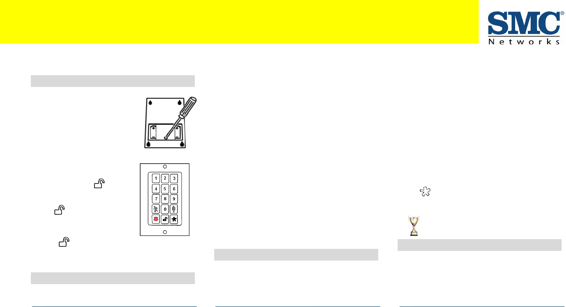
1 Pre-Installation Guidelines
A. With a Phillips screwdriver, remove
the screw from the battery cover in
the back of the key pad and
remove the cover.
B. Find the two supplied CR2 3-volt
lithium batteries.
C. On the front of the key pad, hold
down the 2 and 8 buttons while
inserting one of the batteries in th
back of the key pad (positive end
up).
e
D. Continue to hold down the 2 and
8 buttons until the button
lights green, then release
immediately.
E. The button flashes green 3
times every 5 seconds. This means
the device is in Search mode and
can be added to the TouchScreen.
If the button stops blinking, touch the STAR
to restart Search mode.
butto
F. Insert the other battery and replace the key pad back
cover.
n
2 Adding a Key Pad
A. From the Home screen, touch the Settings widget.
B. When the TouchScreen Keypad screen appears, touch
the numbers to enter the Installer keypad code (this
code is the same for all TouchScreens installed by your
company).
C. When the Technician keyboard pad appears, enter your
Technician ID and touch Done.
D. When the Technician Settings menu appears, select Key
Fobs & Pads > Add a Key Pad. The Locating Key Pads
screen appears.
E. Touch Next, and the system scans the premises for key
pads that can be added, which must meet the following
requirements:
- Defaulted
- Not currently paired with another TouchScreen.
- In Search Mode (blinking 3 times every 5 seconds)
F. Follow the system prompts to complete the add process
and pair the key pad with the TouchScreen.
Note: If no available key pads are found, touch Cancel Key
Pad Add to return to the Technician Settings menu.
G. Arm the system from the key pad to test that the key
pa hd as been added successfully.
3 Deleting a Key Pad
Deleting a key pad from the premises removes it from being
used to perform actions in your security system. You should
delete a key pad:
If the key pad is being relinquished by the customer. ¾
¾ To reset the key pad to factory default settings by
deleting the key pad and re-adding it to the TouchScreen
immediately.
Congratulations on purchasing your SMCWK01-Z
Key Pad.
The SMCMT02-Z Key Pad is a professional state-of-the-art device that lets you arm and disarm your system from additional locations in your home. It also provides an emergency alarm
function.
To delete a key pad from the TouchScreen:
A. Perform steps A through D in step 2, “Adding a Key Pad
to the TouchScreen”.
B. When the Technician Settings menu appears, select Key
Fobs & Pads > Delete a Key Pad. The Remove Key Pad
screen appears.
C. Touch the key pad icon that you want to delete. A
confirmation dialog appears.
D. Touch Yes. The key pad is deleted from the
TouchScreen.
E. After deleting the key pad from the TouchScreen, press
the button to reset the device to default and place
it in Search mode so it can be added to a TouchScreen
again.
4 Troubleshooting
If a key pad does not appear to be working properly or is not
being located by the TouchScreen during the Add process:
¾ Verify that two good batteries have been properly
installed (see step 1, “ .” Pre-Installation Guidelines
¾ Confirm that the key pad has been defaulted.
Congratulations!
You have successfully added key pads.
continued on next page
SMCWK01-Z Key Pad Quick Start Guide
Copyright ©2010 SMC Networks Page 2
All Rights Reserved
SMCWK01-Z 08172010
8/17/10
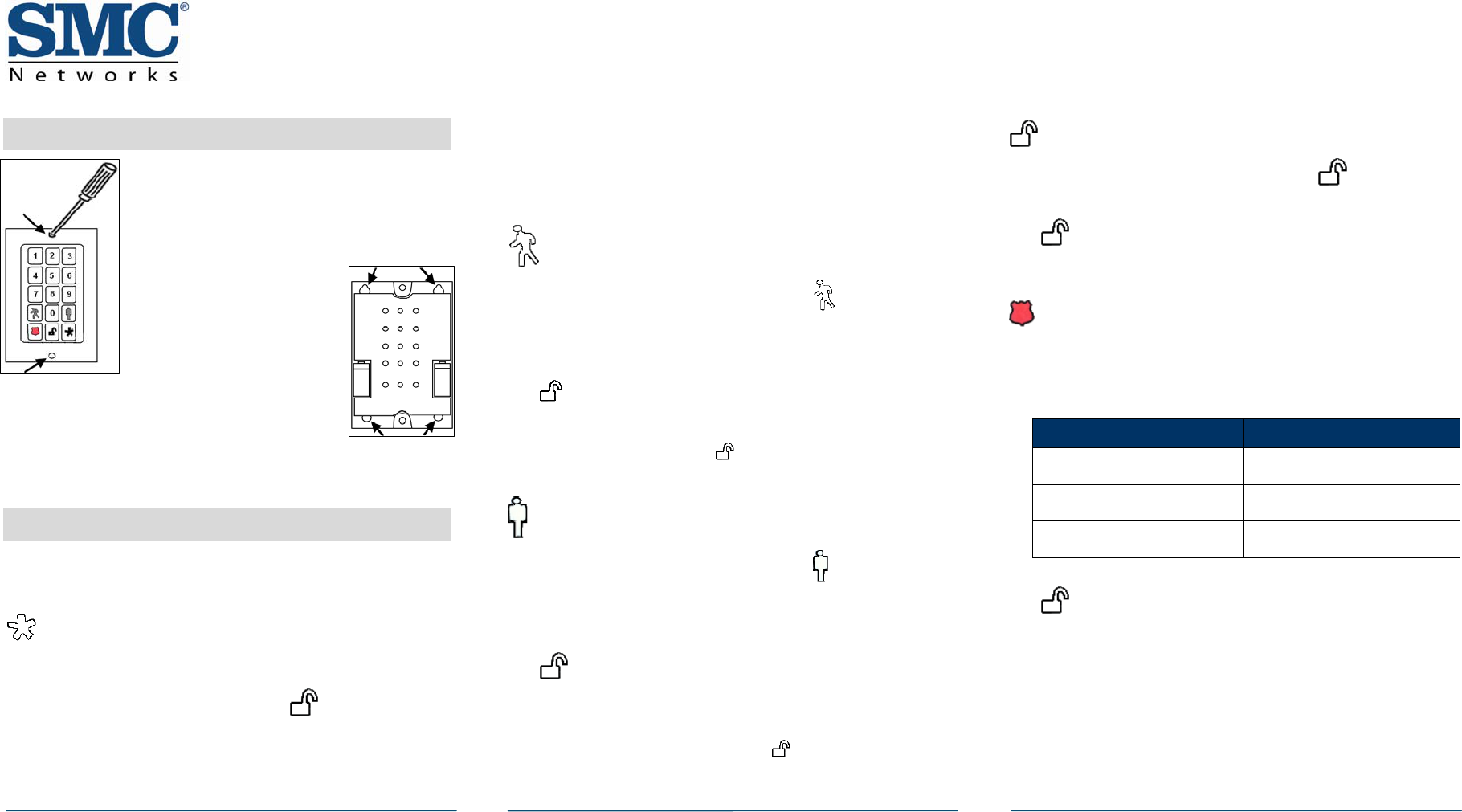
5 Mounting the Key Pad
A. Use a Phillips screwdriver to remove
the faceplate from the front of the key
pad.
B. Behind the circuit board, find the four
holes at the back of the device.
C. Place the key pad on
the wall where you
want it located and use
a pen to mark the
location of the four
holes.
D.
E. Affix the key pad to the installed screws.
Install four screws in the locations
marked on the wall. Do not screw them
in all the way.
F. Replace the faceplate to the front of the key pad.
6 Control Buttons
With the key pad, you can arm the system (in Arm Away or
Arm Stay modes), disarm it, or send an Emergency alarm for
police assistance.
System Status
Press the System Status button to show the current status of
the security system or the device. The button lights to
show the current status of the device and then.
¾ Lights green for 3 seconds if the system is disarmed.
¾ Lights red for 3 seconds if the system is armed.
¾ Lights orange for 3 seconds if the system is not ready to
be armed, such as when a door is open.
¾ Flashes green 3 times every 5 seconds if the key pad has
been defaulted and is ready to pair to the TouchScreen.
Arm Away
Enter a valid keypad code, then press the button to arm
the system in Arm Away mode (no one is in the premises).
For more information about arming mode, refer to the
TouchScreen User Guide.
The button turns red for 3 seconds to show the Exit Delay
started (default 30 seconds—TouchScreen beeps during this
period). If the system is not ready for arming, such as if a
door or window is open, the button flashes orange 7
times.
Arm Stay
Enter a valid keypad code, then press the button to arm
the system in Arm Stay mode (people are in the premises).
For more information about arming mode, refer to the
TouchScreen User Guide.
The button turns red for 3 seconds to indicate the Exit
Delay started (twice as long as the period configured for Arm
Away—up to 120 seconds with no beeping from the
TouchScreen). If the system is not ready for arming, such as
when a door or window is open, the button flashes
orange 7 times.
Disarm
Enter a valid keypad code followed by the button to
disarm the system.
The button turns green for 3 seconds to indicate the
system has been disarmed. There is no Entry Delay period.
Panic
Press and hold the Panic button for about 2 seconds to send
a silent alarm to central monitoring for police assistance.
The button flashes red to indicate the alarm was sent.
The TouchScreen does not react in any way; however, the
History tab on the Security widget shows an alarm was sent.
Also, contact persons will receive email and SMS
notifications if they are configured to do so.
Sensor State LED Display
Arming Red
Disarming Green
System Not Ready to Arm Orange
continued on next page

SMCWK01-Z Key Pad Quick Start Guide
Copyright ©2010 SMC Networks Page 3
All Rights Reserved
SMCWK01-Z 08172010
8/17/10
Compliances
FCC Notice
This device has been designed, constructed, and tested with
for compliance with FCC Rules that regulate intentional and
unintentional radiators. As the user of this device, you are
not permitted to make any alterations or modifications to
this equipment or to use it in any way that is inconsistent
with the information described in this quick-start guide,
without the express written permission of SMC Networks.
Doing so will void your warranty to operate this equipment.
This device complies with Part 15 of the FCC rules.
Operation of this device is subject to the following two
conditions:
1) This device may not cause harmful interference, and
2) This device must accept any interference received,
including interference that may cause undesired operation.
The “IC” designation preceding the radio certification
number indicates that this device complies with the Industry
of Canada specifications.
ETL Notice
This device complies with all ETL and ETLC safety
requirements.
Limitations of Security Products
Security products and alarm systems do not offer guaranteed
protection against burglary, fire, or other emergencies. They
may fail to warn for diverse reasons, including (but not
limited to): power failure, dead batteries, improper
installation, coverage , coverage areas overlooked during
installation, defeat by technically sophisticated intruders,
component failure, or inadequate maintenance. Alarm
systems should be checked weekly to ensure that all devices
are working properly.
AN ALARM SYSTEM IS NOT A SUBSTITUTE FOR INSURANCE.