SNAPPER Generator Manual L0808312
User Manual: SNAPPER SNAPPER Generator Manual SNAPPER Generator Owner's Manual, SNAPPER Generator installation guides
Open the PDF directly: View PDF ![]() .
.
Page Count: 20

OWMer'S
Questions_ Help is just a moment away!
Contact the Local Snapper Service Center
Web: wvcw, snapperocorn or wvcw, briggsandstratton,corn
8 PFR TM
bye& Stratt@. _
_ POWERPRODUCT5
TABLE OF CONTENTS
Safety Rules .................................... 2-4
Know Your Generator ............................. 5
Assembly ...................................... 6-7
Operation .................................... 8-II
Specifications ................................... 12
Maintenance .................................... [2
Storage ........................................ 13
Troubleshooting ................................. 13
Schematic/Wiring Diagram ..................... 14-15
Replacement Parts ............................ 16- [9
Warranty ................................. Last Page
EQUIPMENT
DESCRiPTiON
[_ Read this manual carefully and become
................................ familiar with your generator. Know its
applications, its limitations and any hazards
involved.
This manual describes an engine-driven, revolving field,
alternating current (AC) generator designed to supply
electrical power for operating compatible electrical lighting,
appliances, tools and motor loads.The generator's revolving
field is driven at about 3,600 rpm by a single-cylinder engine.
CAUTION! DO NOT exceed the generator's
wattage/amperage capacity. See "Don't Overload
Generator" on page I I.
Every effort has been made to ensure that information in this
manual is accurate and current. However, we reserve the
right to change, alter or otherwise improve the product and
this document at any time without prior notice.
The Emission Control System for this generator is warranted
for standards set by the Environmental Protection Agency. For
warranty information refer to the engine owner's manual.
In the State of California a spark attester is required by [aw I
(Section 4442 of the California Public Resources Code). I
Other states may have similar laws. Federal laws apply on I
federal bands, if you equip the muffler with a spark arrester, I
it must be maintained in effective working order. I
SAFETY RULES
_k his is the safety alert symbol, it is used to
alert you to potential personal injury hazards.
Obey all safety messages that follow this
symbol to avoid possible injury or death.
The safety alert symbol (_) is used with a signal word
(DANGER, CAUTION,WARNING), a pictorial and/or a
safety message to alert you to hazards. DANGER indicates
a hazard which, if not avoided, will result in death or serious
injury. WARNING indicates a hazard which, if not avoided,
could result in death or serious injury. CAUTION
indicates a hazard which, if not avoided, might result in
minor or moderate injury. CAUTION, when used
without the alert symbol, indicates a situation that could
result in equipment damage. Follow safety messages to
avoid or reduce the risk of injury or death.
[ AwAR-I-G
The engine exhaust from this product contains
[chemicals known to the State of California to cause
[cancer, birth defects, or other reproductive harm.
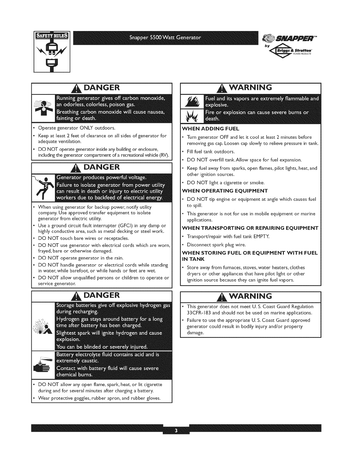
Hazard Symbols and Meanings
Electrocution Electrical Shock Electrical Shock
Toxic Fumes Explosion
,_ _ _'3!'_
Explosive Pressure Chemical Burn
Fire
Hot Surface
SNAPPER TM
bye& 5fraH@n
_WER P_ODU_
DANGER
, Operate generator ONLY outdoors.
, Keep at least 2 feet of clearance on all sides of generator for
adequate ventilation.
, DO NOT operate generator inside any building or enclosure,
including the generator compartment of a recreational vehicle (RV).
DANGER
, When using generator for backup power, notify utility
company. Use approved transfer equipment to isolate
generator from electric utility.
, Use a ground circuit fault interrupter (GFCI) in any damp or
highly conductive area, such as metal decking or steel work.
,DO NOT touch bare wires or receptacles.
,DO NOT use generator with electrical cords which are worn,
frayed, bare or otherwise damaged.
, DO NOT operate generator in the rain.
, DO NOT handle generator or electrical cords while standing
in water, while barefoot, or while hands or feet are wet.
, DO NOT allow unqualified persons or children to operate or
service generator.
DANGER
, DO NOT allow any open flame, spark, heat, or lit cigarette
during and for several minutes after charging a battery.
, Wear protective goggles, rubber apron, and rubber gloves.
|WARNING
WHEN ADDING FUEL
, Turn generator OFF and let it cool at least 2 minutes before
removing gas cap. Loosen cap slowly to relieve pressure in tank.
, Fill fuel tank outdoors.
, DO NOT overfill tank.Allow space for fuel expansion.
, Keep fuel away from sparks, open flames, pilot lights, heat, and
other ignition sources.
, DO NOT light a cigarette or smoke.
WHEN OPERATING EQUIPHENT
.DO NOT tip engine or equipment at angle which causes fuel
to spill.
, This generator is not for use in mobile equipment or marine
applications.
WHEN TRANSPORTING OR REPAiRiNG EQUIPHENT
"Transport/repair with fuel tank EMPTY.
,Disconnect spark plug wire.
WHEN STORING FUEL OR EQUIPMENT WiTH FUEL
iN TANK
.Store away from furnaces, stoves, water heaters, clothes
dryers or other appliances that have pilot light or other
ignition source because they can ignite fuel vapors.
|WARNING
This generator does not meet U. S. Coast Guard Regulation
33CFR-183 and should not be used on marine applications.
Failure to use the appropriate U. S. Coast Guard approved
generator could result in bodily injury and/or property
damage.
811Y PFR*"
bye& Stratt@. _
_ POWERPRODUCTS
WARNING
WHEN ADJUSTING OR NAKING REPAIRSTOYOUR
GENERATOR
. Disconnect the spark plug wire from the spark plug and place
the wire where it cannot contact spark plug.
1 WARNING 1
. DO NOT touch hot surfaces.
.Allow equipment to cool before touching.
CAUTION
. DO NOT tamper with governed speed. Generator supplies
correct rated frequency and voltage when running at governed
speed.
.DO NOT modify generator in any way.
CAUTION
See"Don't Overload Generator" on page II.
Start generator and let engine stabilize before connecting
electrical loads.
Connect electrical loads in OFF position, then turn ON for
operation.
Turn electrical loads OFF and disconnect from generator
before stopping generator.
CAUTION
Use generator only for intended uses.
If you have questions about intended use, ask dealer or call
[-800-3 [ 7-7833.
Operate generator only on level surfaces.
DO NOT expose generator to excessive moisture, dust, dirt,
or corrosive vapors.
DO NOT insert any objects through cooling slots.
If connected devices overheat, turn them off and disconnect
them from generator.
Shut off generator if:
-electrical output is lost;
-equipment sparks, smokes, or emits flames;
-unit vibrates excessively.
SNAPPER TM
bye& 5fraH@n
_WER P_ODU_
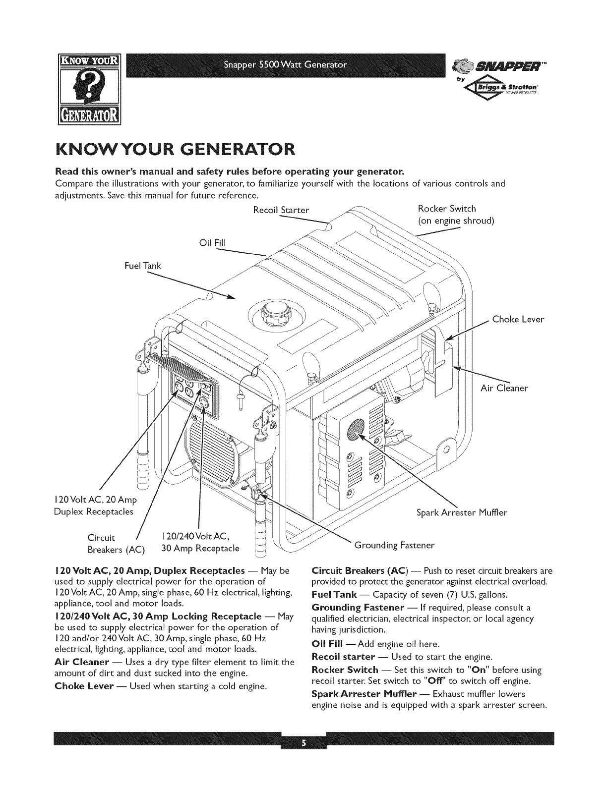
KNOWYOUR GENERATOR
Read this owner's manual and safety rules before operating your generator.
Compare the illustrations with your generator, to familiarize yourself with the locations of various controls and
adjustments. Save this manual for future reference.
Recoil Starter Rocker Switch
(on engine shroud)
Fuel Tank
Choke Lever
Air Cleaner
120 Volt AC, 20 Amp
Duplex Receptacles
Circuit
Breakers (AC)
120/240 Volt AC,
30 Amp Receptacle
120 Volt AC, 20 Amp, Duplex Receptacles -- May be
used to supply electrical power for the operation of
120Volt AC, 20 Amp, single phase, 60 Hz electrical lighting,
appliance_ tool and motor loads.
120/240Volt AC, 30 Amp Locking Receptacle -- May
be used to supply electrical power for the operation of
120 and/or 240Volt AC, 30Amp, single phase, 60 Hz
electrical, lighting, appliance, tool and motor loads.
Air Cleaner -- Uses a dry type filter element to limit the
amount of dirt and dust sucked into the engine.
Choice Lever -- Used when starting a cold engine.
Spark Arrester Muffler
Grounding Fastener
Circuit Breakers (AC) -- Push to reset circuit breakers are
provided to protect the generator against electrical oveHoad.
Fuel Tank -- Capacity of seven (7) U.S. gallons.
Grounding Fastener -- If required, please consult a
qualified electrician, electrical inspector, or local agency
having jurisdiction.
Oil Fill --Add engine oil here.
Recoil starter -- Used to start the engine.
Rocker Switch -- Set this switch to "On" before using
recoil starter. Set switch to "Off" to switch off engine.
Spark Attester Muffler- Exhaust muffler lowers
engine noise and is equipped with a spark arrester screen.
81 glIDPFI@*"
_ POWERPRODUCTS
ASSEMBLY
Your generator requires some assembly and is ready for
use after it has been properly serviced with the
recommended oil and fuel.
Ifyou have any problems with the assembly of your
generator, contact the local Snapper service center.
IMPORTANT: Any attempt to run the unitbefore ithas
been serviced with the recommended oil will result in an
engine failure.
Remove Generator From Carton
• Setthe cartonon a rigidflatsurfacewith"ThisSideUp"
arrows pointing upward.
• Carefully open the top flaps of the shipping carton.
• Cut down corners at one end of carton from top to
bottom and lay that side of carton down flat.
• Remove all packing material, carton fillers, etc.
• Remove the generator from the shipping carton.
Carton Contents
Check all contents. If any parts are missing or damaged,
contact the local Snapper service center.
• The generator
• Generator and engine owner's manuals
• Locking 30Amp plug
• Engine oil
•Wheel kit
installWheel Kit
The wheel kit is designed to greatly improve the portability
of your generator.
NOTE: Wheel kit is not intended for over-the-road use.
You will need a socket wrench with 1/2" or 13mm sockets
and a needle-nose pliers to install this kit.
.
3.
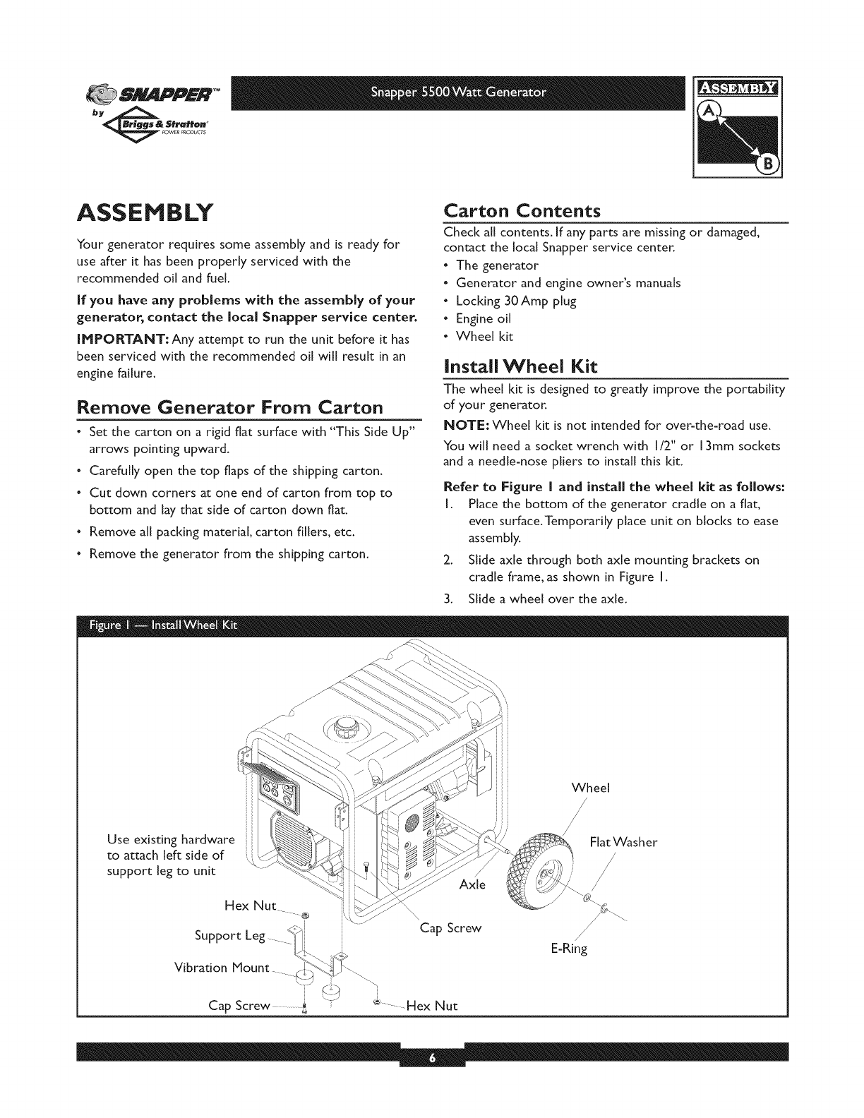
Refer to Figure Iand installthe wheel kitas follows:
I. Place the bottom of the generator cradle on a flat,
even surface.Temporarily place unit on blocks to ease
assembly.
Slide axle through both axle mounting brackets on
cradle frame, as shown in Figure I.
Slide a wheel over the axle.
Use existing hardware ::
to attach left side of
support leg to unit '\ ....
Hex Nut ®
i
Support
Vibration Mount
i
Cap Screw ..........._ "J
Axle
Cap Screw
Wheel
/
Fiat Washer
/
/
E-Ring
SNAPPER TM
bye& 5fraH@n
_WER P_ODU_
NOTE: Be sure to install both wheels with the air
pressure valve on the outboard side.
4. Place the e-ring onto the groove in the axle.You may
add the flat washer if desired.
NOTE: Use retaining pins instead of e-dip, if applicable.
5. Place one end of the needle nose pliers on the bottom
of the axle and the other end of the pliers on top of
the e=ring. Seat the e=ring by pressing the pliers closed.
6. Repeat step 3 through 5 to secure second wheel.
7. Remove the temporary blocks.
8. Attach the vibration mounts to the support leg with
30mm capscrews and lock nuts.
9. To aid support leg assembly, rest generator on cradle,
engine end down. Remove the existing hardware from
the left unit vibration mount with 13mm wrench. Use
the same hardware to attach the support leg.
I 0. Attach the other side of the support leg with a 20mm
cap screw and lock nut. Rest generator on wheels and
support leg.
I I. Check each fastener to ensure it is secure and the
tires are inflated between 15=40 PSI.
BEFORE STARTING TIlE
ENGINE
Add Engine Oil and Fuel
• Place generator on a level surface.
• Refer to engine owner's manual and follow oil and fuel
recommendations and instructions.
CAUTION
. Refer to engine manual for oil and fuel fill information.
.Damage to equipment resulting from failure to follow this
instruction will void warranty.
NOTE: Check oil often during engine break-in. Refer to
engine owner's manual for recommendations.
NOTE: The generator assembly rotates on a prelubricated
and sealed ball bearing that requires no additional
lubrication for the life of the bearing.
81 IIDPFR*"
bye& Stratt@. _
_ POWERPRODUCT5
USING THE GENERATOR
System Ground
The generator has a system ground that connects the
generator frame components to the ground terminals on
the AC output receptacles.The system ground is connected
to the AC neutral wire (see "Equipment Description",
earlier in this manual).
Special Requirements
There may be Federal or State Occupational Safety and
Health Administration (OSHA) regulations, local codes, or
ordinances that apply to the intended use of the generator.
Please consult a qualified electrician, electrical inspector, or
the local agency having jurisdiction.
• In some areas, generators are required to be registered
with local utility companies.
• If the generator is used at a construction site, there may
be additional regulations which must be observed.
Connecting to a Building's Electrical
System
Connections for standby power to a building's electrical
system must be made by a qualified electrician.The
connection must isolate the generator power from utility
power, and must comply with all applicable laws and
electrical codes.
DANGER
. When using generator for backup power, notify utility
company. Use approved transfer equipment to isolate
generator from electric utility.
. Use a ground fault circuit interrupter (GFCI) in any damp or
highly conductive area, such as metal decking or steel work.
. DO NOT touch bare wires or receptacles.
. DO NOT use generator with electrical cords which are worn,
frayed, bare or otherwise damaged.
. DO NOT operate generator in the rain.
. DO NOT handle generator or electrical cords while standing
in water, while barefoot, or while hands or feet are wet.
. DO NOT allow unqualified persons or children to operate or
service generator.
OPERATING THE
GENERATOR
CAUTION
See"Don't Overload Generator" on page I I.
Start generator and let engine stabilize before connecting
electrical loads.
Connect electrical loads in OFF position, then turn ON for
operation.
Turn electrical loads OFF and disconnect from generator
before stopping generator.
Starting the Engine
Disconnect all electrical loads from the generator. Use the
following start instruction steps by numerical order:
I. Make sure unit is on a level surface.
IHPORTANT: Failure to start and operate unit on a level
surface will cause the unit not to start or shut down during
operation.
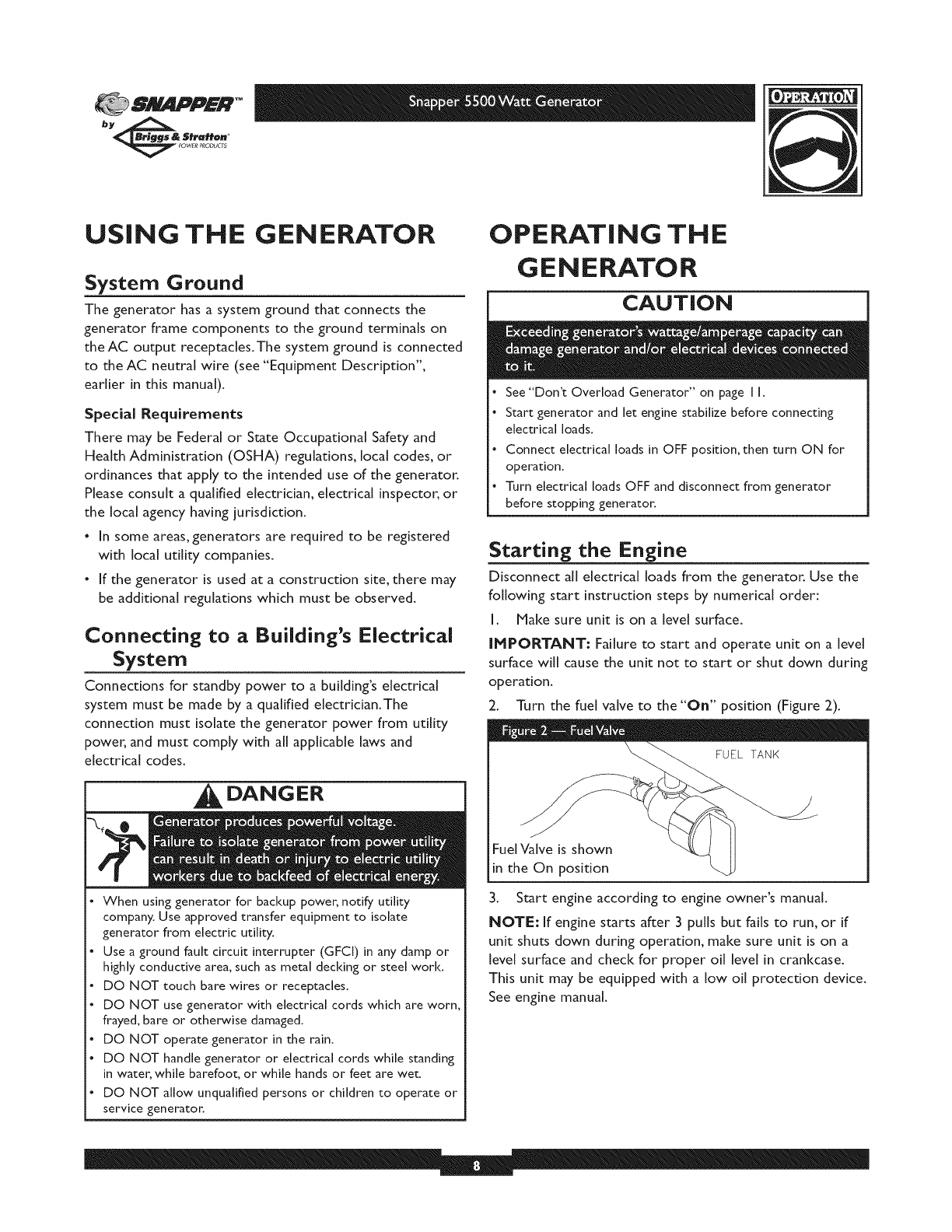
2. Turn the fuel valve to the "On" position (Figure 2).
FueIValve is shown
in the On position
3. Start engine according to engine owner's manual.
NOTE: If engine starts after 3 pulls but fails to run, or if
unit shuts down during operation, make sure unit is on a
level surface and check for proper oil level in crankcase.
This unit may be equipped with a low oil protection device.
See engine manual.
SNAPPER TM
bye& 5fraH@n
_WER P_ODU_
Connecting Electrical Loads
• Let engine stabilize and warm up for a few minutes after
starting.
• Plug in and turn on the desired 120 and/or 240VoItAC,
single phase, 60 Hz electrical loads.
• DO NOT connect 240Volt loads to the [20Volt duplex
receptacles.
• DO NOT connect 3-phase loads to the generator.
• DO NOT connect 50 Hz loads to the generator.
• DO NOT OVERLOAD THE GENERATOR. See
"Don't Overload Generator" on page I I.
Stopping the Engine
1. Unplug all electrical loads from generator panel
receptacles. NEVER start or stop engine with electrical
devices plugged in and turned ON.
2. Let engine run at no4oad for several minutes to stabilize
internal temperatures of engine and generator.
3. Turn engine off according to engine owner's manual
4. Move fuel valve to "Off' position.
COLD WEATHER
OPERATION
Under certain weather conditions (temperatures below
40°F [4°C] and a high dew point), your generator may
experience icing of the carburetor and/or the crankcase
breather system.
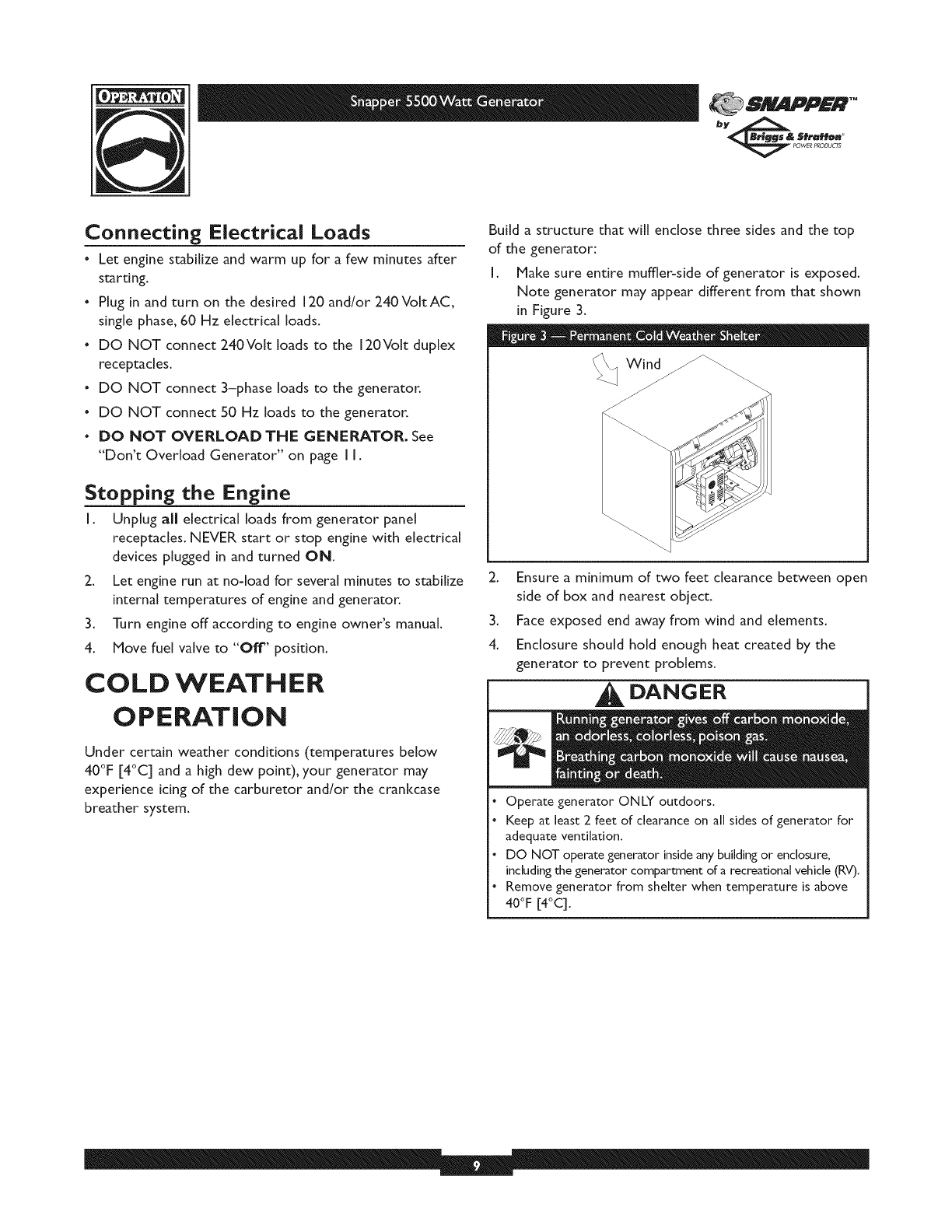
Build a structure that will enclose three sides and the top
of the generator:
[. Make sure entire muffler-side of generator is exposed.
Note generator may appear different from that shown
in Figure 3.
2. Ensure a minimum of two feet clearance between open
side of box and nearest object.
3. Face exposed end away from wind and elements.
4. Enclosure should hold enough heat created by the
generator to prevent problems.
DANGER
Operate generator ONLY outdoors.
Keep at least 2 feet of clearance on all sides of generator for
adequate ventilation.
DO NOT operate generator inside an), building or enclosure,
including the generator compartment of a recreational vehicle (RV).
Remove generator from shelter when temperature is above
40°F [4°C].
811IJ_PFR TM
bye& Stratt@. _
_ POWERPRODUCT5
RECEPTACLES
CAUTION
• NEVER attempt to power a device requiring more
amperage than generator or receptacle can supply.
DO NOT overload the generator. See "Don't Overload
Generator".
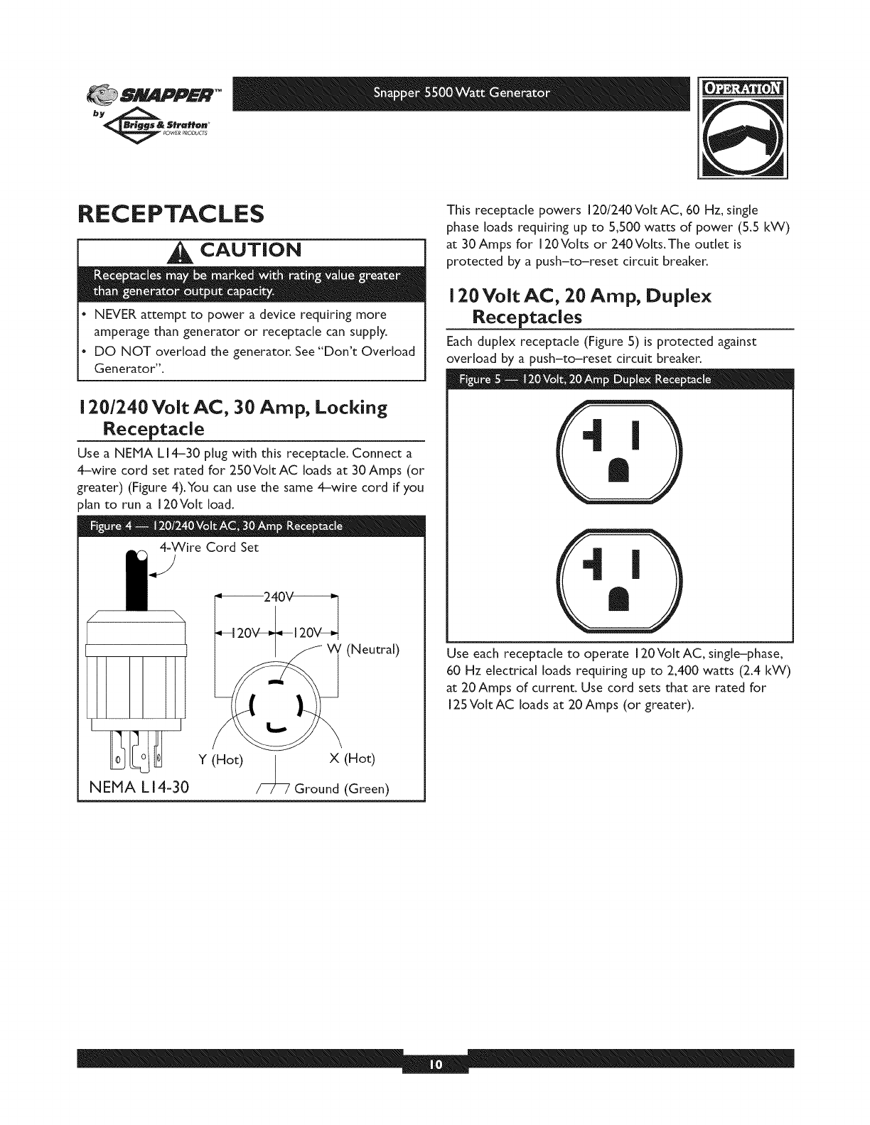
1201240 Volt AC, 30 Amp, Locking
Receptacle
Use a biEMA L14-30 plug with this receptacle. Connect a
4-wire cord set rated for 250Volt AC loads at 30Amps (or
greater) (Figure 4).You can use the same 4-wire cord if you
_[an to run a 120Volt load.
4=Wire Cord Set
NEMA LI4=30
Y (Hot)
(Neutral)
X (Hot)
Ground (Green)
This receptacle powers I20/240VoItAC, 60 Hz, single
phase loads requiring up to 5,500 watts of power (5.5 kW)
at 30 Amps for 120Volts or 240Volts.The outlet is
protected by a push-to-reset circuit breaker.
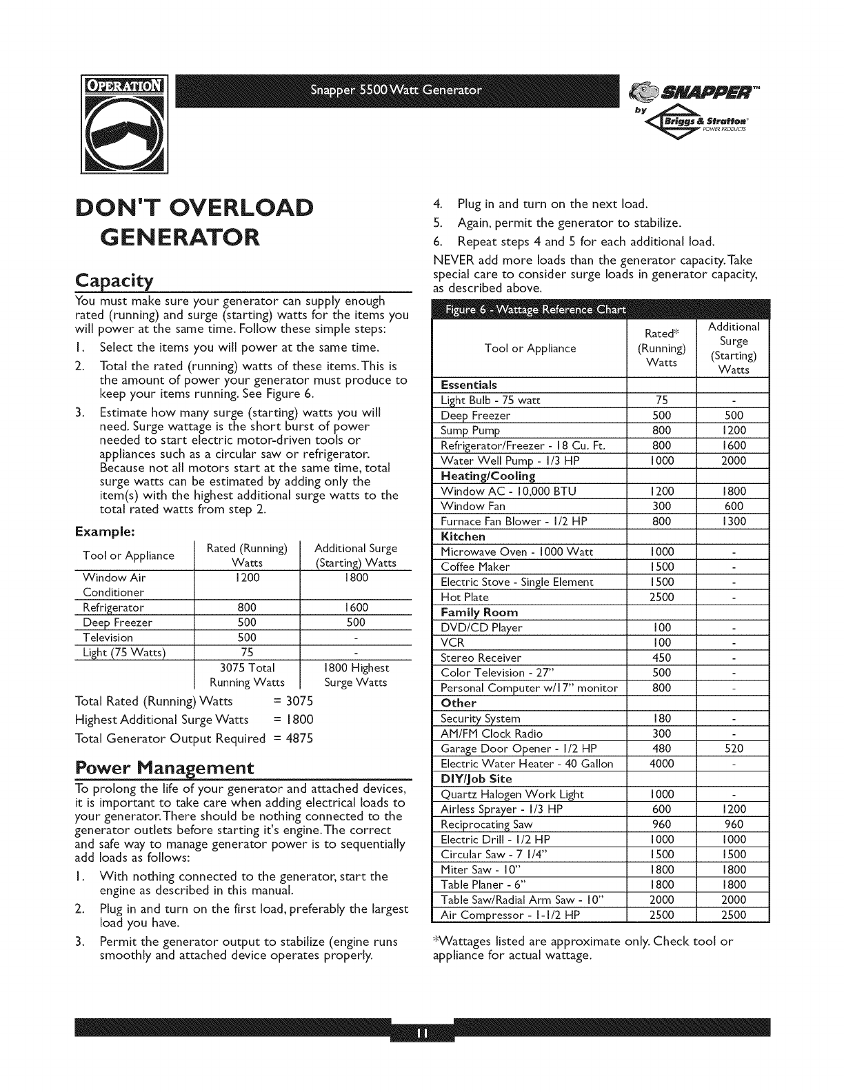
120 Volt AC, 20 Amp, Duplex
Receptacles
Each duplex receptacle (Figure 5) is protected against
overload by a push-to-reset circuit breaker.
Use each receptacle to operate 120Volt AC, single-phase,
60 Hz electrical loads requiring up to 2,400 watts (2.4 kW)
at 20 Amps of current. Use cord sets that are rated for
125 Volt AC loads at 20 Amps (or greater).
SNAPPER TM
bye& 5fraH@n
_WER P_ODU_
DON'T OVERLOAD
GENERATOR
acity
You must make sure your generator can supply enough
rated (running) and surge (starting) watts for the items you
will power at the same time. Follow these simple steps:
I. Select the items you will power at the same time.
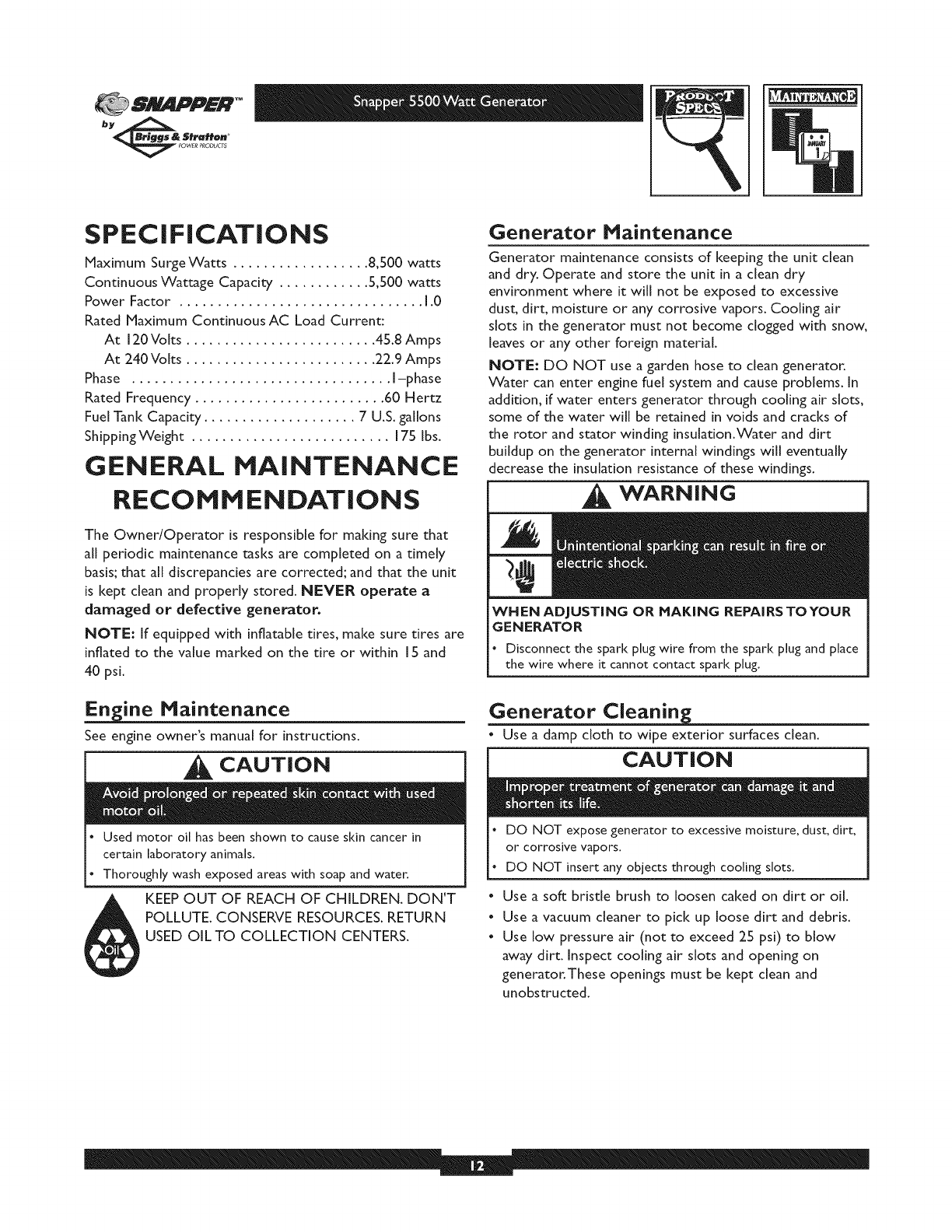
2. Total the rated (running) watts of these items.This is
the amount of power your generator must produce to
keep your items running. See Figure 6.
3. Estimate how many surge (starting) watts you will
need. Surge wattage is the short burst of power
needed to start electric motor-driven tools or
appliances such as a circular saw or refrigerator.
Because not all motors start at the same time, total
surge watts can be estimated by adding only the
item(s) with the highest additional surge watts to the
total rated watts from step 2.
Example:
Tool or Appliance
Window Air
Conditioner
Refrigerator
Deep Freezer
Television
Light (75 Watts)
Rated (Running)
Watts
1200
800
5O0
50O
75
3075 Total
RunningWatts
Total Rated (Running)Watts = 3075
Highest Additional Surge Watts =1800
Total Generator Output Required = 4875
Additional Surge
(Starting) Watts
1800
1600
5OO
1800 Highest
Surge Watts
Power Management
To prolong the life of your generator and attached devices,
it is important to take care when adding electrical loads to
your generator.There should be nothing connected to the
generator outlets before starting it's engine.The correct
and safe way to manage generator power is to sequentially
add loads as follows:
I. With nothing connected to the generator, start the
engine as described in this manual.
2. Plug in and turn on the first load, preferably the largest
load you have.
3. Permit the generator output to stabilize (engine runs
smoothly and attached device operates properly.
4. Plug in and turn on the next load.
5. Again, permit the generator to stabilize.
6. Repeat steps 4 and 5 for each additional load.
NEVER add more loads than the generator capacity.Take
special care to consider surge loads in generator capacity,
as described above.
Additional
Rated*
Tool or Appliance (Running) Surge
Watts (Starting)
Watts
Essentials
Light Bulb -75 watt 75
Deep Freezer 500 500
Sump Pump 800 1200
Refrigerator/Freezer -18Cu, Ft. 800 1600
Water Well Pump -I/3 HP 1000 2000
Heating/Cooling
Window AC - I0,000 BTU 1200 1800
Window Fan 300 600
Furnace FanBlower- I/2 HP 800 1300
Kitchen
Microwave Oven -1000 Watt [000
Coffee Maker [500
Electric Stove - Single Element 1500
Hot Plate 2500
Family Room
DVD/CD Player 100
VCR 100
Stereo Receiver 450
Color Television - 27" 500
Personal Computer w/I 7" monitor 800
Other
Security System 180
AM/FM Clock Radio 300
Garage Door Opener - I/2 HP 480 520
Electric Water Heater - 40 Gallon 4000
DIY/Job Site
Quartz Halogen Work Light I000
Airless Sprayer - I/3 HP 600 1200
Reciprocating Saw 960 960
Electric Drill - I/2 HP 1000 1000
Circular Saw-7I/4" 1500 1500
Miter Saw - I0" 1800 1800
Table Planer - 6" 1800 1800
Table Saw/RadialArm Saw - 10" 2000 2000
Air Compressor - I-I/2 HP 2500 2500
*Wattages listed are approximate only. Check tool or
appliance for actual wattage.
8 PFR*"
bye& Stratt@. _
_ POWERPRODUCT5
SPECiFiCATiONS
Maximum Surge Watts .................. 8,500 watts
Continuous Wattage Capacity ............ 5,500 watts
Power Factor ................................ 1.0
Rated Maximum Continuous AC Load Current:
At 120 Volts ......................... 45.8 Amps
At 240 Volts ......................... 22.9 Amps
Phase .................................. I-phase
Rated Frequency ......................... 60 Hertz
Fuel Tank Capacity .................... 7 U.S. gallons
ShippingWeight .......................... 175 Ibs.
GENERAL MAINTENANCE
RECOMMENDATIONS
The Owner/Operator is responsible for making sure that
all periodic maintenance tasks are completed on a timely
basis; that all discrepancies are corrected; and that the unit
is kept clean and properly stored. NEVER operate a
damaged or defective generator.
NOTE: If equipped with inflatable tires, make sure tires are
inflated to the value marked on the tire or within 15 and
40 psi.
E__n ine Maintenance
See engine owner's manual for instructions.
CAUTION
. Used motor oil has been shown to cause skin cancer in
certain laboratory animals.
. Thoroughly wash exposed areas with soap and water.
KEEP OUT OF REACH OF CHILDREN. DON'T
POLLUTE. CONSERVE RESOURCES. RETURN
USED OIL TO COLLECTION CENTERS.
Generator Maintenance
Generator maintenance consists of keeping the unit clean
and dry. Operate and store the unit in a clean dry
environment where it will not be exposed to excessive
dust, dirt, moisture or any corrosive vapors. Cooling air
slots in the generator must not become clogged with snow,
leaves or any other foreign material.
NOTE: DO NOT use a garden hose to clean generator.
Water can enter engine fuel system and cause problems. In
addition, if water enters generator through cooling air slots,
some of the water will be retained in voids and cracks of
the rotor and stator winding insulation.Water and dirt
buildup on the generator internal windings will eventually
decrease the insulation resistance of these windings.
WARNING
WHEN ADJUSTING OR NAKING REPAIRSTOYOUR
GENERATOR
Disconnect the spark plug wire from the spark plug and place
the wire where it cannot contact spark plug.
Generator Cleanin_
•Use a damp cloth to wipe exterior surfaces dean.
CAUTION
o
o
o
DO NOT expose generator to excessive moisture, dust, dirt,
or corrosive vapors.
DO NOT insert any objects through cooling slots.
Use a soft bristle brush to loosen caked on dirt or oil.
Use a vacuum cleaner to pick up loose dirt and debris.
Use low pressure air (not to exceed 25 psi) to blow
away dirt. Inspect cooling air slots and opening on
generator.These openings must be kept clean and
unobstructed.
SNAPPER TM
bye& 5fraH@n
_WER P_ODU_
STORAGE
The generator should be started at least once every seven
days and allowed to run at least 30 minutes. If this cannot
be done and you must store the unit for more than
30 days, use the following guidelines to prepare it for
storage.
Generator Storage
• Clean the generator as outlined in "Generator Cleaning".
• Check that cooling air slots and openings on generator
are open and unobstructed.
WARN IN G
. DO NOT place a storage cover over a hot generator.
.Let equipment cool for a sufficient time before placing the
cover on the equipment.
Engine Storage
See engine owner's manual for instructions.
Other Storage Tips
• To prevent gum from forming in fuel system or on
essential carburetor parts, add fuel stabilizer into fuel
tank and fill with fresh gasoline. Run the unit for several
minutes to circulate the additive through the carburetor.
The unit and fuel can then be stored for up to
24 months. Fuel stabilizer can be purchased locally.
• DO NOT store gasoline from one season to another
unless it has been treated as described above.
• Replace fuel container if it starts to rust. Rust and/or dirt
in fuel can cause problems if it's used with this unit.
• Store unit in a clean and dry area.
TROUBLESHOOTING
Problem
No AC output is available, but
generator is running.
Generator runs good at no=load
but "bogs" down" when loads are
connected.
Generator will not start; or starts
and runs rough.
Generator shuts down during
operation.
Generator lacks power.
Cause
I. One of the circuit breakers is
open.
2. Fault in generator.
3. Poor connection or defective cord
set.
4. Connected device is bad.
I. Short circuit in a connected load.
2. Generator is overloaded.
3. Shorted generator circuit.
Low oil level.
I. Out of fuel.
2. Low oil level.
Correction
I. Reset circuit breaker.
2. Contact Authorized service facility.
3. Check and repair.
4. Connect another device that is in
good condition.
I. Disconnect shorted electrical load.
2. See "Don't Overload Generator".
3. Contact Authorized service facility.
Load is too high.
Fill crankcase to proper level or place
generator on level surface.
I. Fill fuel tank.
2. Fill crankcase to proper level or
place generator on level surface.
See "Don't Overload Generator".
SA_gMDPFR TM
by_& Stratt@."
_ POWERPRODUCT5
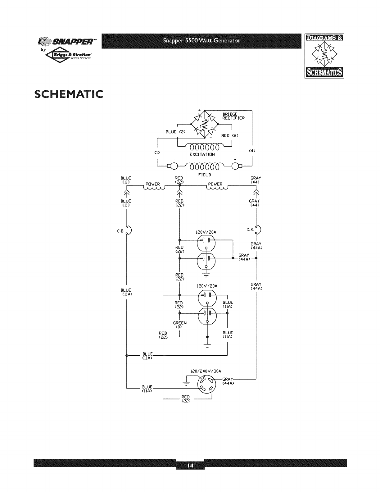
SCHEMATIC
BRIDGE
BLUE (2) _x_ _/" RED (6)
i L_ (4)
(,) ExcI,ATIo.
FIELD
BLUE RED
BLUE RE D
(ll) (22)
__ BLUE
(l*A)
__ BLUE
(IIA)
BLUE
(hA)
12OV/20A
R
(2
RED
(22)
GRAY
(44)
GRAY
(44)
GRAY
(44A)
GRAY
_--(44A)--4
120V/2OA
(22)
(o)
RED I
(22)
UE
)
BLUE
(IIA)
GRAY
(44A)
120/240V/3OA
_GRAY--
RED J
(22)
SNAPPER TM
bye& 5fraH@n
_WERPRODU_S
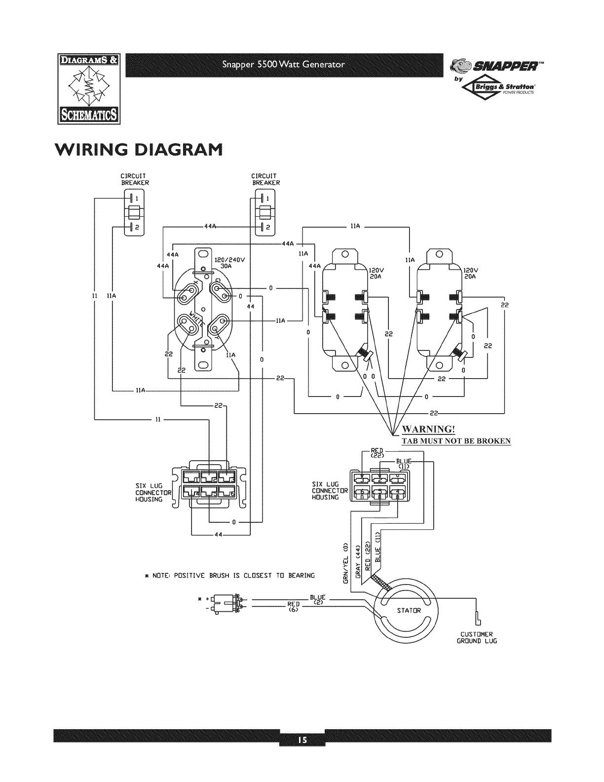
WiRiNG DIAGRAM
II IIA
22
IIA
llA
120V 120V
20A 20A
m NOTE= POSITIVE BRUSH IS CLOSEST TO BEARING
_ BLUE
__ RED (2) --
(6)
CUSTOMER
GROUND LUG
81_g_lPPFR*"
bye& Stratt@. _
_ POWERPRODUCT5
I
2J_
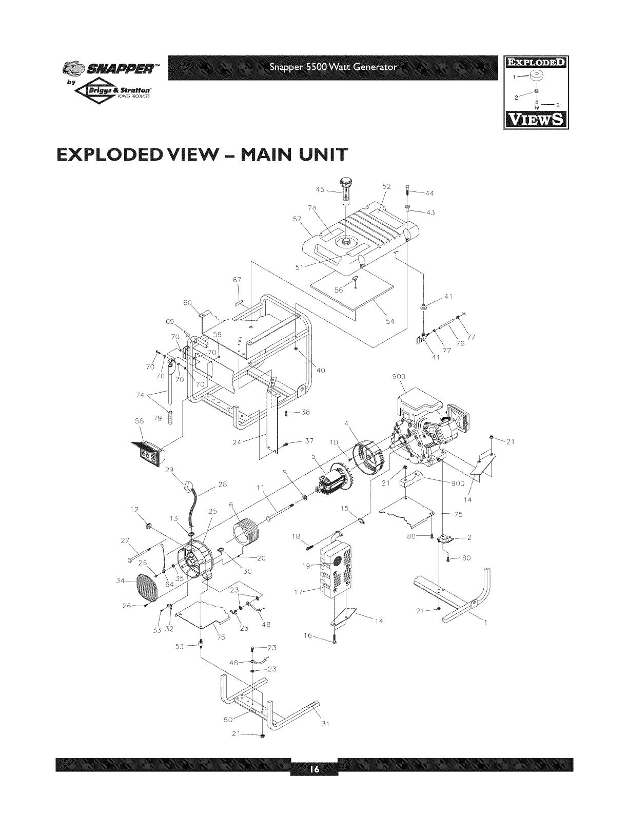
EXPLODED ViEW - HAIN UNiT
78
57
52
12 ,\\
27 \\
6o \
69_
70
29\
15 25
67
\5O
21
11
48
\4O
56
4
10
51
54
9oo
\\
15
80_
21
77
\ 76
77
I
2J_
g--3
SNAPPER TM
bye& 5fraH@n
_WER P_ODU_
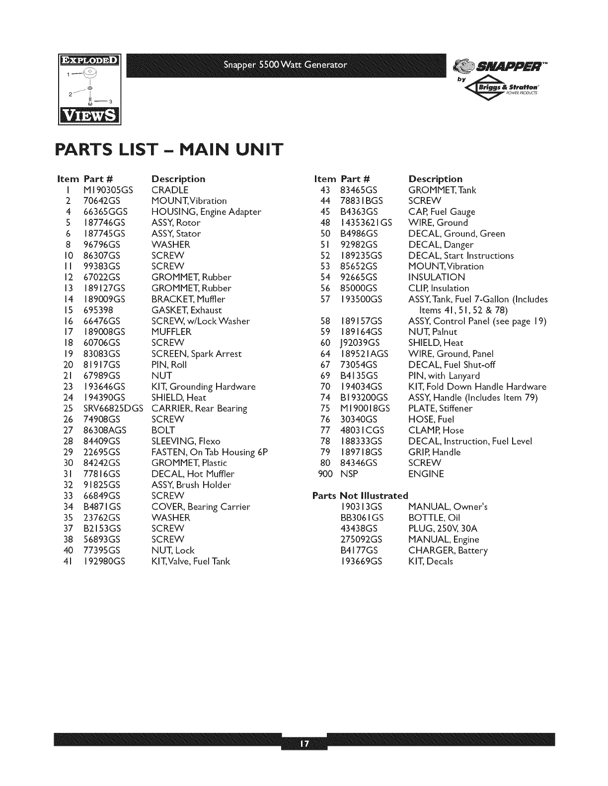
PARTS LiST- HAIN UNiT
Item Part # Description Item
I M 190305GS CRADLE 43
2 70642GS MOUNT, Vibration 44
4 66365GGS HOUSING, Engine Adapter 45
5 187746GS ASSY_Rotor 48
6 187745GS ASSY, Stator 50
8 96796GS WASHER 5 I
I0 86307GS SCREW 52
II 99383GS SCREW 53
12 67022GS GROMMET, Rubber 54
13 189127GS GROMMET, Rubber 56
14 189009GS BRACKET, Muffler 57
15 695398 GASKET, Exhaust
16 66476GS SCREW, w/LockWasher 58
17 189008GS MUFFLER 59
18 60706GS SCREW 60
19 83083GS SCREEN, Spark Arrest 64
20 81917GS PIN, Roll 67
21 67989GS NUT 69
23 193646GS KIT, Grounding Hardware 70
24 194390GS SHIELD, Heat 74
25 SRV66825DGS CARRIER, Rear Bearing 75
26 74908GS SCREW 76
27 86308AGS BOLT 77
28 84409GS SLEEVING, Flexo 78
29 22695GS FASTEN, OnTab Housing 6P 79
30 84242GS GROMMET, Plastic 80
31 77816GS DECAL, Hot Muffler 900
32 91825GS ASSY, Brush Holder
33 66849GS SCREW Parts
34 B4871GS COVER, Bearing Carrier
35 23762GS WASHER
37 B2153GS SCREW
38 56893GS SCREW
40 77395GS NUT, Lock
41 192980GS KIT,Valve, Fuel Tank
Part #
83465GS
78831BGS
B4363GS
14353621GS
B4986GS
92982GS
189235GS
85652GS
92665GS
85000GS
93500GS
89157GS
89164GS
J92039GS
189521AGS
73054GS
B4135GS
194034GS
B 193200GS
M 190018GS
30340GS
48031CGS
188333GS
189718GS
84346GS
NSP
Description
GROMMET,Tank
SCREW
CAR Fuel Gauge
WIRE, Ground
DECAL, Ground, Green
DECAL, Danger
DECAL, Start Instructions
MOUNT, Vibration
INSULATION
CLIR Insulation
ASSY,Tank, Fuel 7=Gallon (Includes
Items 41,51,52 & 78)
ASSY, Control Panel (see page 19)
NUT, Palnut
SHIELD, Heat
WIRE, Ground, Panel
DECAL, Fuel Shut=off
PIN, with Lanyard
KIT, Fold Down Handle Hardware
ASSY_ Handle (Includes Item 79)
PLATE, Stiffener
HOSE, Fuel
CLAMP, Hose
DECAL, Instruction, Fuel Level
GRIR Handle
SCREW
ENGINE
Not Illustrated
190313GS MANUAL, Owner's
BB3061GS BOTTLE, Oil
43438GS PLUG, 250V, 30A
275092GS MANUAL, Engine
B4177GS CHARGER, Battery
193669GS KIT, Decals
81_gAPPFR*"
bye& Stratt@. _
_ POWERPRODUCTS
I
2J_
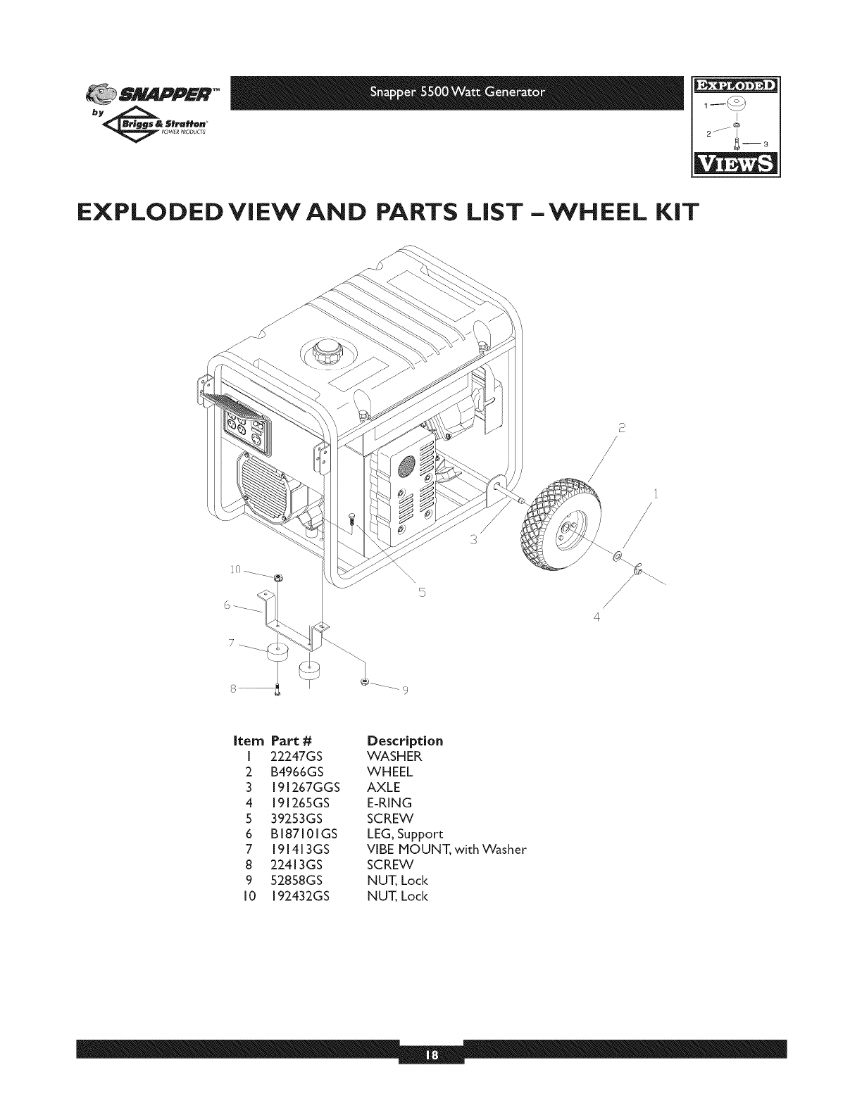
EXPLODED ViEW AND PARTS LiST -WHEEL KiT
/
4
Item Part #
I 22247GS
2 B4966GS
3191267GGS
4 191265GS
539253GS
6 BI87101GS
7 191413GS
8 22413GS
9 52858GS
10 192432GS
Description
WASHER
WHEEL
AXLE
E-RING
SCREW
LEG, Support
VIBE MOUNT, with Washer
SCREW
NUT, Lock
NUT, Lock

I
2J_4--3
SNAPPER TM
bye& 5fraH@n
_WER P_ODU_S
EXPLODED VIEW AND PARTS LiST - CONTROL PANEL
5
4
6 7 7
6
\
5
8
2
15
9
12
10
16\
11
15
14
17
Item Part #
I 188914GS
:2 188889GS
3189167GS
4 18918:2GS
5 189166GS
6 68759GS
7 189165GS
8 84198GS
9 75:207GS
I0 43437GS
I I 189164GS
1:2 84543CGS
13 93857GS
14 188890GS
15 8:2308GS
16 :2:2694GS
17 19:2:241GS
Description
COVER, Lid, Control Panel
CONTROL PANEL, Compact
CLIP, Hinge Pin Retainer
SPRING, Hinge, Pin
PIN, Hinge, Cover, Compact
OUTLET, 1:20V,:20A, Duplex
NUT, Palnut, Pushnut
CAR Circuit Breaker
BREAKER, Circuit
OUTLET, 1:20/:240V Locking, 30A
NUT, Palnut, Pushnut
SCREW
BAR, Retaining
COVER, Back, Control Panel
SCREW
HOUSING, Receptacle
SCREW
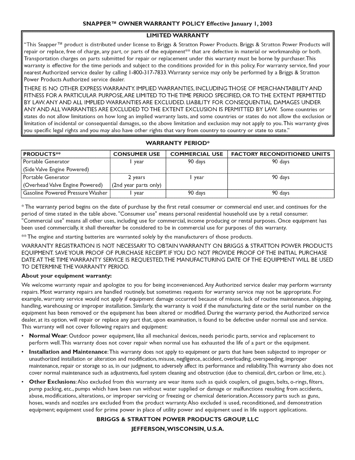
SNAPPER TM OWNERWARI_NTY POLICY Effective January I, 2003
LiMiTED WARRANTY
"This Snapper TM product is distributed under license to Brigs & Stratton Power Products. Briggs & Stratton Power Products will
repair or replace, free of charge, any part, or parts of the equipment _ that are defective in material or workmanship or both.
Transportation charges on parts submitted for repair or replacement under this warranty must be borne by purchaser.This
warranty is effective for the time periods and subject to the conditions provided for in this policy. For warranty service, find your
nearest Authorized service dealer by calling 1-800=317-7833.Warranty service may only be performed by a Briggs & Stratton
Power Products Authorized service dealer.
THERE IS NO OTHER EXPRESSWARRANTY. IMPLIEDWARRANTIES, INCLUDING THOSE OF MERCHANTABILITYAND
FITNESSFOR A PARTICULAR PURPOSE,ARE LIMITED TO THE TIME PERIOD SPECIFIED,OR TO THE EXTENT PERMITTED
BY LAW.ANY AND ALL IMPLIEDWARRANTIES ARE EXCLUDED. LIABILITY FOR CONSEQUENTIAL DAMAGES UNDER
ANY AND ALL WARRANTIES ARE EXCLUDED TO THE EXTENT EXCLUSION IS PERMITTED BY LAW. Some countries or
states do not allow limitations on how long an implied warranty lasts,and some countries or states do not allow the exclusion or
limitation of incidental or consequential damages,so the above limitation and exclusion may not apply to you.This warranty gives
you specific legal rights and you may also have other rights that vary from country to country or state to state."
WARRANTY PERIOD*
PRODUCTS** CONSUMER USE COMMERCIAL USE FACTORY RECONDITIONED UNITS
Portable Generator I year 90 days 90 days
(Side Va[ve Engine Powered)
Portable Generator 2 years [ year 90 days
(Overhead Valve Engine Powered) (2nd year parts only)
Gasoline Powered PressureWasher I year 90 days 90 days
_ The warranty period begins on the date of purchase by the first retail consumer or commercial end user, and continues for the
period of time stated in the table above. "Consumer use" means personal residential household use by a retail consumer.
"Commercial use" means all other uses, including use for commercial, income producing or rental purposes. Once equipment has
been used commercially, it shah thereafter be considered to be in commercial use for purposes of this warranty.
_The engine and starting batteries are warranted solely by the manufacturers of those products.
WARRANTY REGISTRATION IS NOT NECESSARYTO OBTAIN WARRANTY ON BRIGGS & STRATTON POWER PRODUCTS
EQUIPMENT. SAVEYOUR PROOF OF PURCHASE RECEIPT. IFYOU DO NOT PROVIDE PROOF OFTHE INITIAL PURCHASE
DATE AT THE TIME WARRANTY SERVICE IS REQUESTED, THE MANUFACTURING DATE OF THE EQUIPMENT WILL BE USED
TO DETERMINE THE WARRANTY PERIOD.
About your equipment warranty:
We welcome warranty repair and apologize to you for being inconvenienced.Any Authorized service dealer may perform warranty
repairs. Most warranty repairs are handled routinely, but sometimes requests for warranty service may not be appropriate. For
example, warranty service would not apply if equipment damage occurred because of misuse, lack of routine maintenance, shipping,
handling, warehousing or improper installation. Similarly, the warranty is void if the manufacturing date or the serial number on the
equipment has been removed or the equipment has been altered or modified. During the warranty period, the Authorized service
dealer, at its option, will repair or replace any part that, upon examination, is found to be defective under normal use and service.
This warranty will not cover following repairs and equipment:
• Normal Wear: Outdoor power equipment, like all mechanical devices, needs periodic parts, service and replacement to
perform well.This warranty does not cover repair when normal use has exhausted the life of a part or the equipment.
• installation and Maintenance:This warranty does not apply to equipment or parts that have been subjected to improper or
unauthorized installation or alteration and modification, misuse, negligence, accident, overloading, overspeeding, improper
maintenance, repair or storage so as, in our judgment, to adversely affect its performance and reliability.This warranty also does not
cover normal maintenance such as adjustments, fuel system cleaning and obstruction (due to chemical, dirt, carbon or lime, etc.).
• Other Exclusions:Also excluded from this warranty are wear items such as quick couplers, oil gauges, belts, o-rings, filters,
pump pacldng, etc., pumps which have been run without water supplied or damage or malfunctions resulting from accidents,
abuse, modifications, alterations, or improper servicing or freezing or chemical deterioration.Accessory parts such as guns,
hoses, wands and nozzles are excluded from the product warranty.Also excluded is used, reconditioned, and demonstration
equipment; equipment used for prime power in place of utility power and equipment used in life support applications.
BRIGGS & STRATTON POWER PRODUCTS GROUP, LLC
JEFFERSON,WISCONSIN, U.S.A.
