SNAPPER Generator Manual L0808313
User Manual: SNAPPER SNAPPER Generator Manual SNAPPER Generator Owner's Manual, SNAPPER Generator installation guides
Open the PDF directly: View PDF ![]() .
.
Page Count: 20
OwMer _S anuai
Questions? Help is just a moment away!
Contact your Local Snapper Service Center
Web: www.snapperocom or www.briggsandstratton.com 0 _ 4
Slt IPPFR TM
bye& Stratton
V POWERPRODUCT5
TABLE OF CONTENTS
Safety Rules .................................... 2-4
Know Your Generator ............................ S
Assembly ....................................... 6
Operation ..................................... 7-9
Product Specifications /Maintenance ................ l0
Storage ........................................ I I
Troubleshooting ................................. 12
Notes ......................................... 13
Schematic/Wiring Diagram ..................... 14-I S
Replacement Parts ............................ 16-19
Warranty ................................. Last Page
EQUIPMENT
DESCRiPTiON
_____ Read this manual carefully and become
............................... familiar with your generator. Know its
applications, its limitations and any hazards
involved.
The generators are an engine-driven, revolving field,
alternating current (AC) generator. It was designed to
supply electrical power for operating compatible electrical
lighting, appliances, tools and motor loads. The generator's
revolving field is driven at about 3,600 rpm by a single-
cylinder engine.
CAUTION! DO NOT exceed the generator's
wattage/amperage capacity. See "Don't Overload
Generator" on page 9.
Every effort has been made to ensure that information in this
manual is accurate and current. However, we reserve the
right to change, alter or otherwise improve the product and
this document at any time without prior notice.
The Emission Control System for this generator is warranted
for standards set by the Environmental Protection Agency.
For warranty information refer to the engine owner's manual
In the State of California a spark attester is required by [aw I
(Section 4442 of the California Public Resources Code). I
Other states may have similar laws. Federal laws apply on I
federal bands, if you equip the muffler with a spark arrester, I
it must be maintained in effective working order. I
SAFETY RULES
_k his is the safety alert symbol, it is used to
alert you to potential personal injury
hazards. Obey all safety messages that follow
this symbol to avoid possible injury or death.
The safety alert symbol (_) is used with a signal word
(DANGER, CAUTION, WARNING), a pictorial and/or a
safety message to alert you to hazards. DANGER
indicates a hazard which, if not avoided, will result in death
or serious injury. WARNING indicates a hazard which, if
not avoided, cauld result in death or serious injury.
CAUTION indicates a hazard which, if not avoided, might
result in minor or moderate injury. CAUTION, when
used without the alert symbol, indicates asituation that
could result in equipment damage. Follow safety messages
to avoid or reduce the risk of injury or death.
[AwAR-I-G
The engine exhaust from this product contains
Ichemicals known to the State of California to cause
[cancer, birth defects, or other reproductive harm.
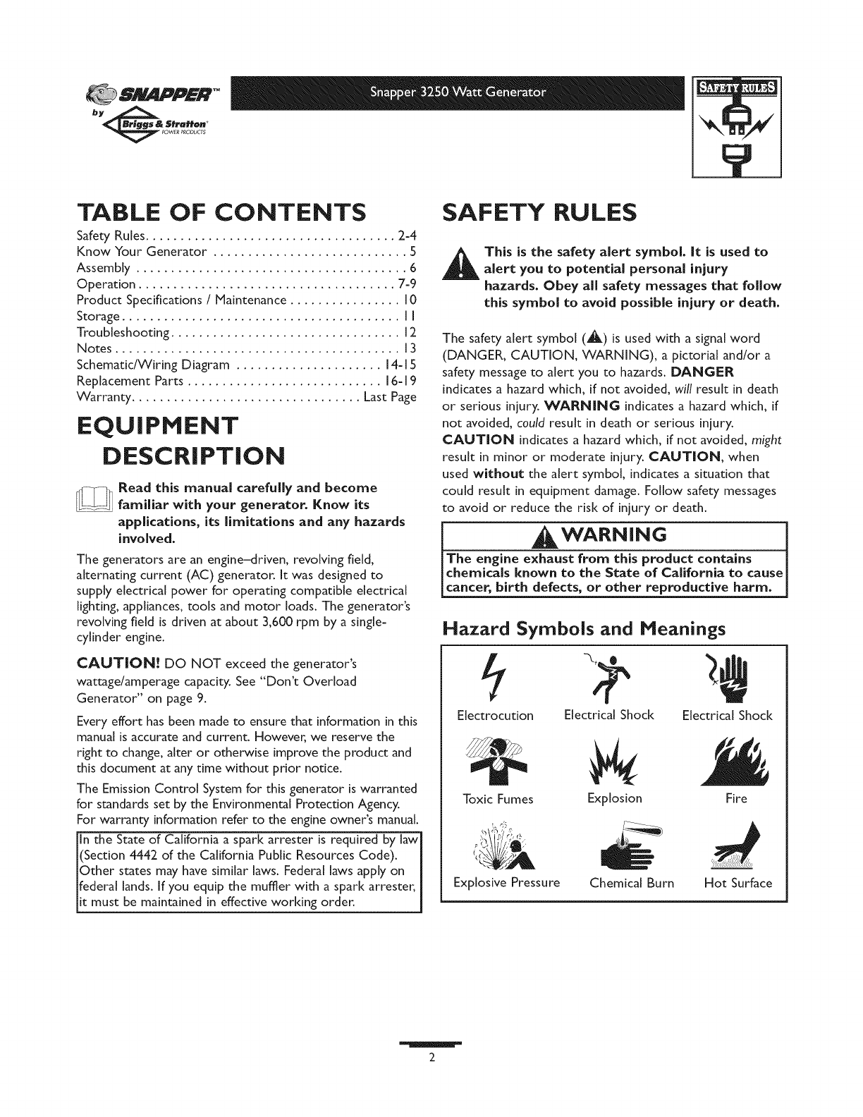
Hazard Symbols and Meanings
Electrocution Electrical Shock Electrical Shock
Toxic Fumes Explosion
Explosive Pressure
l .............
Chemical Burn
Fire
Hot Surface
2
SiU PER TM
bYB__r_s& Sfr_H@n
_ _w_R PRo_u_
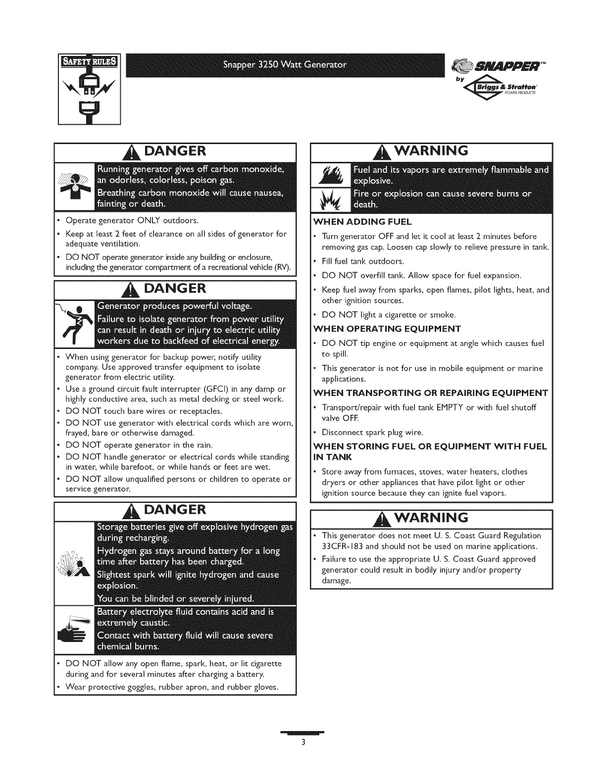
|DANGER
, Operate generator ONLY outdoors.
, Keep at least 2 feet of clearance on all sides of generator for
adequate ventilation.
, DO NOT operate generator inside any building or enclosure,
including the generator compartment of a recreational vehicle (RV).
DANGER
. When using generator for backup power, notify utility
company. Use approved transfer equipment to isolate
generator from electric utility.
, Use a ground circuit fault interrupter (GFCI) in any damp or
highly conductive area, such as metal decking or steel work.
,DO NOT touch bare wires or receptacles.
,DO NOT use generator with electrical cords which are worn,
frayed, bare or otherwise damaged.
, DO NOT operate generator in the rain.
, DO NOT handle generator or electrical cords while standing
in water, while barefoot, or while hands or feet are wet.
, DO NOT allow unqualified persons or children to operate or
service generator.
DANGER
, DO NOT allow any open flame, spark, heat, or lit cigarette
during and for several minutes after charging a battery.
, Wear protective goggles, rubber apron, and rubber gloves.
WARNING
WHEN ADDING FUEL
, Turn generator OFF and let it cool at least 2 minutes before
removing gas cap. Loosen cap slowly to relieve pressure in tank.
, Fill fuel tank outdoors.
, DO NOT overfill tank. Allow space for fuel expansion.
, Keep fuel away from sparks, open flames, pilot lights, heat, and
other ignition sources.
, DO NOT light a cigarette or smoke.
WHEN OPERATING EQUIPHENT
, DO NOT tip engine or equipment at angle which causes fuel
to spill.
, This generator is not for use in mobile equipment or marine
applications.
WHEN TRANSPORTING OR REPAiRiNG EQUIPHENT
" Transport/repair with fuel tank EMPTY or with fuel shutoff
valve OFE
. Disconnect spark plug wire.
WHEN STORING FUEL OR EQUIPMENT WiTH FUEL
iN TANK
, Store away from furnaces, stoves, water heaters, clothes
dryers or other appliances that have pilot light or other
ignition source because they can ignite fuel vapors.
WARNING
This generator does not meet U. S. Coast Guard Regulation
33CFR-183 and should not be used on marine applications.
Failure to use the appropriate U. S. Coast Guard approved
generator could result in bodily injury and/or property
damage.
3
slu pFifr
bye& Stratton
_ POWERPRODUCTS
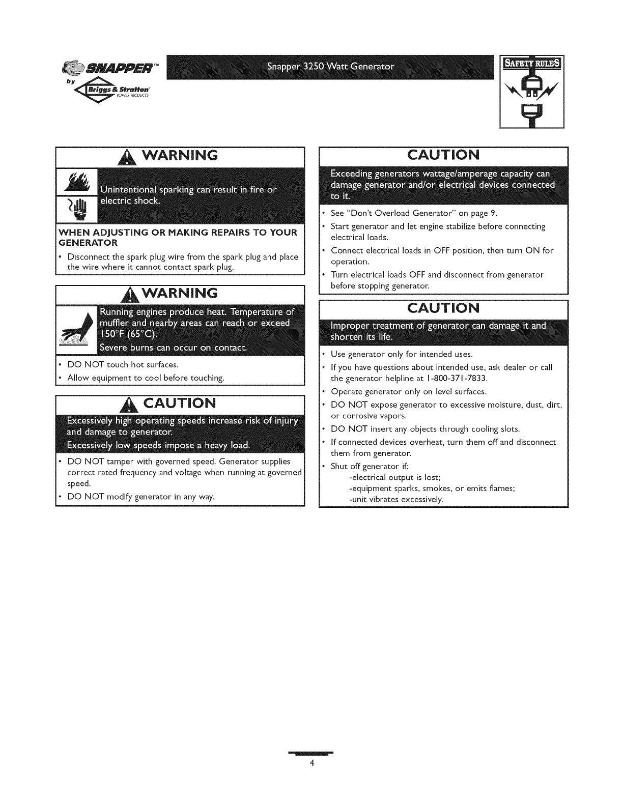
WARNING
WHEN ADJUSTING OR MAKING REPAIRS TO YOUR
GENERATOR
. Disconnect the spark plug wire from the spark plug and place
the wire where it cannot contact spark plug.
I WARNING 1
, DO NOT touch hot surfaces.
, Allow equipment to cool before touching.
CAUTION
.DO NOT tamper with governed speed. Generator supplies
correct rated frequency and voltage when running at governed
speed.
, DO NOT modify generator in any way.
CAUTION
See "Don't Overload Generator" on page 9.
Start generator and let engine stabilize before connecting
electrical loads.
Connect electrical loads in OFF position, then turn ON for
operation.
Turn electrical loads OFF and disconnect from generator
before stopping generator.
CAUTION
Use generator only for intended uses.
If you have questions about intended use, ask dealer or call
the generator helpline at 1-800-371-7833.
Operate generator only on level surfaces.
DO NOT expose generator to excessive moisture, dust, dirt,
or corrosive vapors.
DO NOT insert any objects through cooling slots.
If connected devices overheat, turn them off and disconnect
them from generator.
Shut off generator if."
-electrical output is lost;
-equipment sparks, smokes, or emits flames;
-unit vibrates excessively.
4
SNAPPER TM
bY B__r_s& Sfr_H@n
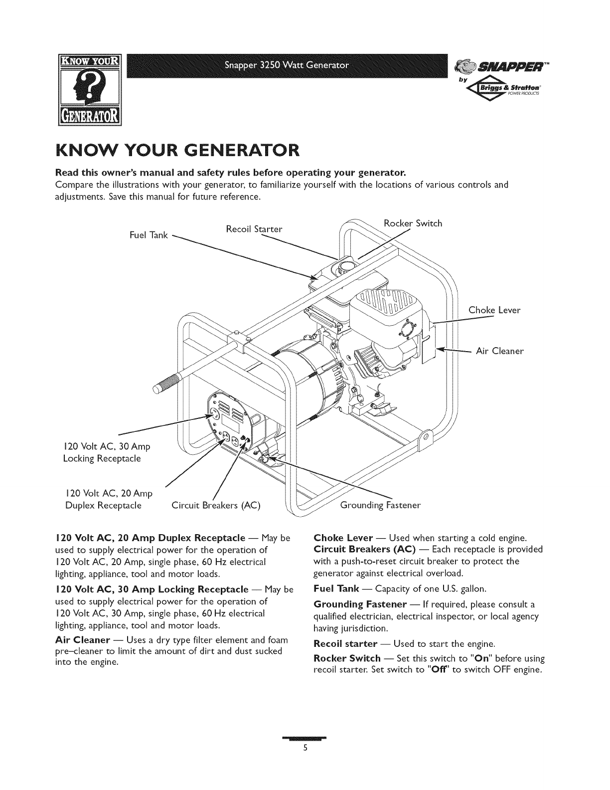
KNOW YOUR GENERATOR
Read this owner's manual and safety rules before operating your generator°
Compare the illustrations with your generator, to familiarize yourseff with the locations of various controls and
adjustments. Save this manual for future reference.
Fuel Tank Recoil Starter Rocker Switch
Choke Lever
Air Cleaner
120 Volt AC, 30 Amp
Locking Receptacle
120 Volt AC, 20 Amp
Duplex Receptacle Circuit Breakers (AC) Grounding Fastener
120 Volt AC, 20 Amp Duplex Receptacle -- May be
used to supply electrical power for the operation of
120 Volt AC, 20 Amp, single phase, 60 Hz electrical
lighting, appliance, tool and motor loads.
120 Volt AC, 30 Amp Locking Receptacle -- May be
used to supply electrical power for the operation of
120 Volt AC, 30 Amp, single phase, 60 Hz electrical
lighting, appliance, tool and motor loads.
Air Cleaner -- Uses a dry type filter element and foam
pre-cleaner to limit the amount of dirt and dust sucked
into the engine.
Choice Lever -- Used when starting a cold engine.
Circuit Breakers (AC) -- Each receptacle is provided
with a push=to=reset circuit breaker to protect the
generator against electrical overload.
Fuel Tank -- Capacity of one U.S. gallon.
Grounding Fastener -- [f required, please consult a
qualified electrician, eJectrJca[ inspector, or iota[ agency
having jurisdiction.
Recoil starter -- Used to start the engine.
Rocker Switch -- Set this switch to "On" before using
recoil starter. Set switch to "Off' to switch OFF engine.
5
SlUgoPR'R TM
bye& Stratton
V POWERPRODUCTS
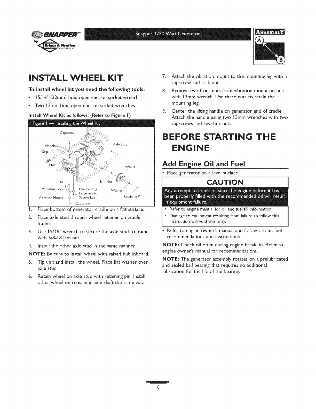
iNSTALL WHEEL KiT
To install wheel kit you need the following tools:
•15/16" (22mm) box, open end, or socket wrench
•Two 13mm box, open end, or socket wrenches
Install Wheel Kit as follows: (Refer to Figure I)
Nut
Jam Nut
Mounting Washer
/
Vibration Mount _ Secure Leg Retaining Pin
/
Capscrew
I. Place bottom of generator cradle on a fiat surface.
2. Place axle stud through wheel retainer on cradle
frame.
3. Use [5/[6" wrench to secure the axle stud to frame
with 5/8-18 jam nut.
4. Install the other axle stud in the same manner.
NOTE: Be sure to install wheel with raised hub inboard.
5. Tip unit and install the wheel. Place flat washer over
axle stud.
6. Retain wheel on axle stud with retaining pin. Install
other wheel on remaining axle shaft the same way.
7. Attach the vibration mount to the mounting leg with a
capscrew and loci< nut.
8. Remove two front nuts from vibration mount on unit
with 13mm wrench. Use these nuts to retain the
mounting leg.
9. Center the lifting handle on generator end of cradle.
Attach the handle using two 13mm wrenches with two
capscrews and two hex nuts.
BEFORE STARTING THE
ENGINE
Add Engine Oil and Fuel
• Place generator on a level surface.
CAUTION
. Refer to engine manual for oil and fuel fill information.
. Damage to equipment resulting from failure to follow this
instruction will void warranty.
• Refer to engine owner's manual and follow oil and fuel
recommendations and instructions.
NOTE: Check oil often during engine break-in. Refer to
engine owner's manual for recommendations.
NOTE: The generator assembly rotates on a prelubricated
and sealed ball bearing that requires no additional
lubrication for the life of the bearing.
6
SiU PER TM
bYB__r_s& Sfr_H@n
_ _w_R PRo_u_
USING THE GENERATOR
System Ground
The generator has a system ground that connects the
generator frame components to the ground terminals on
the AC output receptacles. The system ground is
connected to the AC neutral wire (see "Equipment
Description", earlier in this manual).
Special Requirements
There may be Federal or State Occupational Safety and
Health Administration (OSHA) regulations, local codes, or
ordinances that apply to the intended use of the generator.
Please consult a qualified electrician, electrical inspector, or
the local agency having jurisdiction.
• In some areas, generators are required to be registered
with local utility companies.
• If the generator is used at a construction site, there may
be additional regulations which must be observed.
Connecting to a Building's Electrical
System
Connections for standby power to a building's electrical
system must be made by a qualified electrician. The
connection must isolate the generator power from utility
power, and must comply with all applicable laws and
electrical codes.
DANGER
. When using generator for backup powel, notify utility
company. Use approved transfer equipment to isolate
generator from electric utility.
.Use a ground fault circuit interrupter (GFCI) in any damp or
highly conductive area, such as metal decking or steel work.
.DO NOT touch bare wires or receptacles.
.DO NOT use generator with electrical cords which are worn,
frayed, bare or otherwise damaged.
.DO NOT operate generator in the rain.
.DO NOT handle generator or electrical cords while standing
in water, while barefoot, or while hands or feet are wet.
. DO NOT allow unqualified persons or children to operate or
service generator.
OPERATING THE
GENERATOR
CAUTION
See "Don't Overload Generator" on page 9.
Start generator and let engine stabilize before connecting
electrical loads.
Connect electrical loads in OFF position, then turn ON for
operation.
Turn electrical loads OFF and disconnect from generator
before stopping generator.
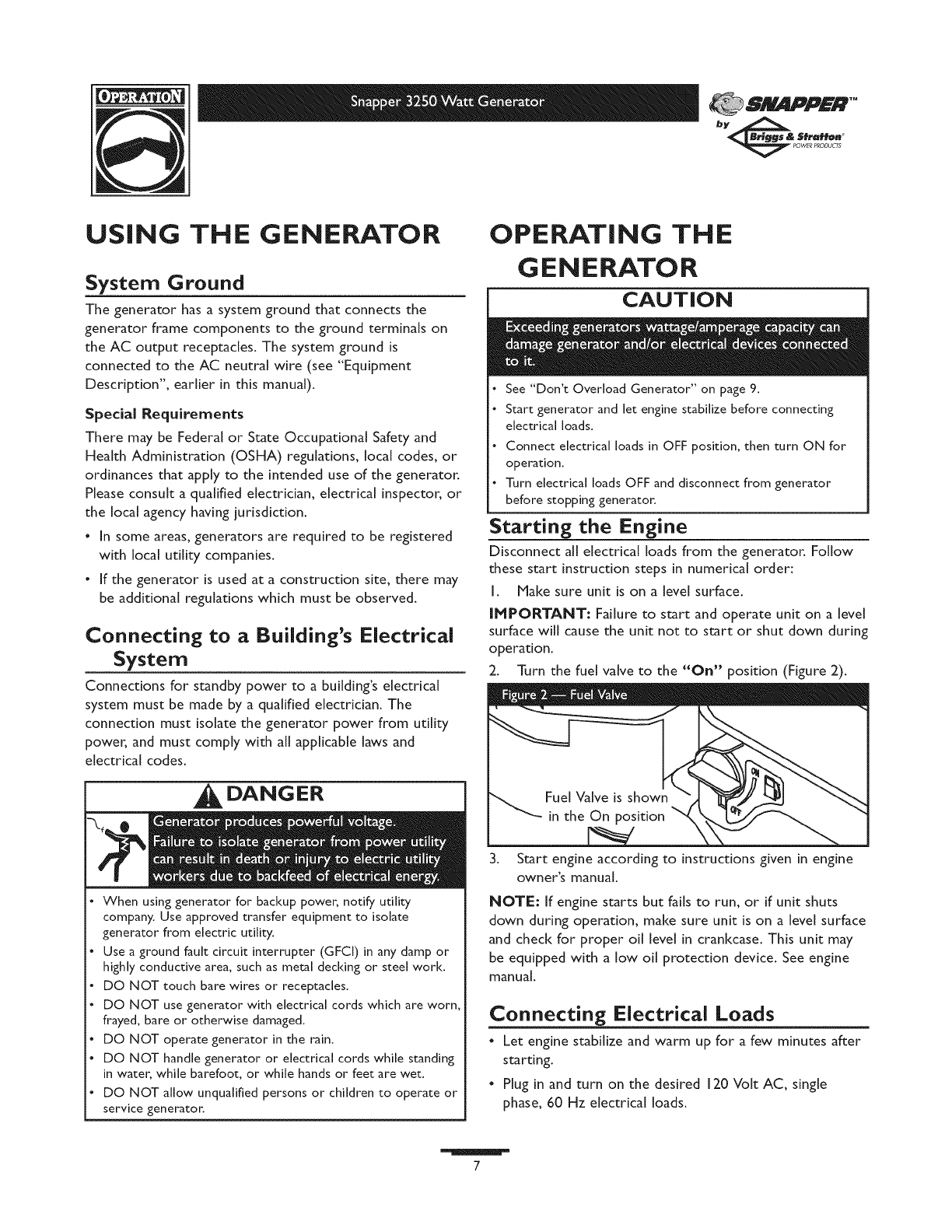
Starting the Engine
Disconnect all electrical loads from the generator. Follow
these start instruction steps in numerical order:
1. Make sure unit is on a [eve[ surface.
IMPORTANT: Failure to start and operate unit on a level
surface will cause the unit not to start or shut down during
operation.
2. Turn the fuel valve to the "On" position (Figure 2).
3. Start engine according to instructions given in engine
owner's manual
NOTE: If engine starts but fails to run, or if unit shuts
down during operation, make sure unit is on a level surface
and check for proper oil level in crankcase. This unit may
be equipped with a low oil protection device. See engine
manual.
Connecting Electrical Loads
•Let engine stabilize and warm up for a few minutes after
starting.
• Plug in and turn on the desired 120 Volt AC, single
phase, 60 Hz electrical loads.
7
SlUgoPFR TM
bye& Stratton
_ POWERPROOUCTS
• DO NOT connect 240 Volt loads to the [ 20 Volt duplex
receptacles.
• DO NOT connect 3-phase loads to the generator.
• DO NOT connect 50 Hz loads to the generaton
• DO NOT OVERLOAD THE GENERATOR. See
"Don't Overload Generator" on page 9.
Stopping the Engine
I. Unplug all electrical loads from generator panel
receptacles. NEVER start or stop engine with electrical
devices plugged in and turned ON.
2. Let engine run at no-load for 30 seconds to stabilize
internal temperatures of engine and generator.
3. Turn engine off according to instructions given in
engine owner's manual.
4. Move fuel valve to "Off' position.
RECEPTACLES
CAUTION
• NEVER attempt to power a device requiring more
amperage than generator or receptacle can supply.
• DO NOT overload the generator. See "Don't Overload
Generator".
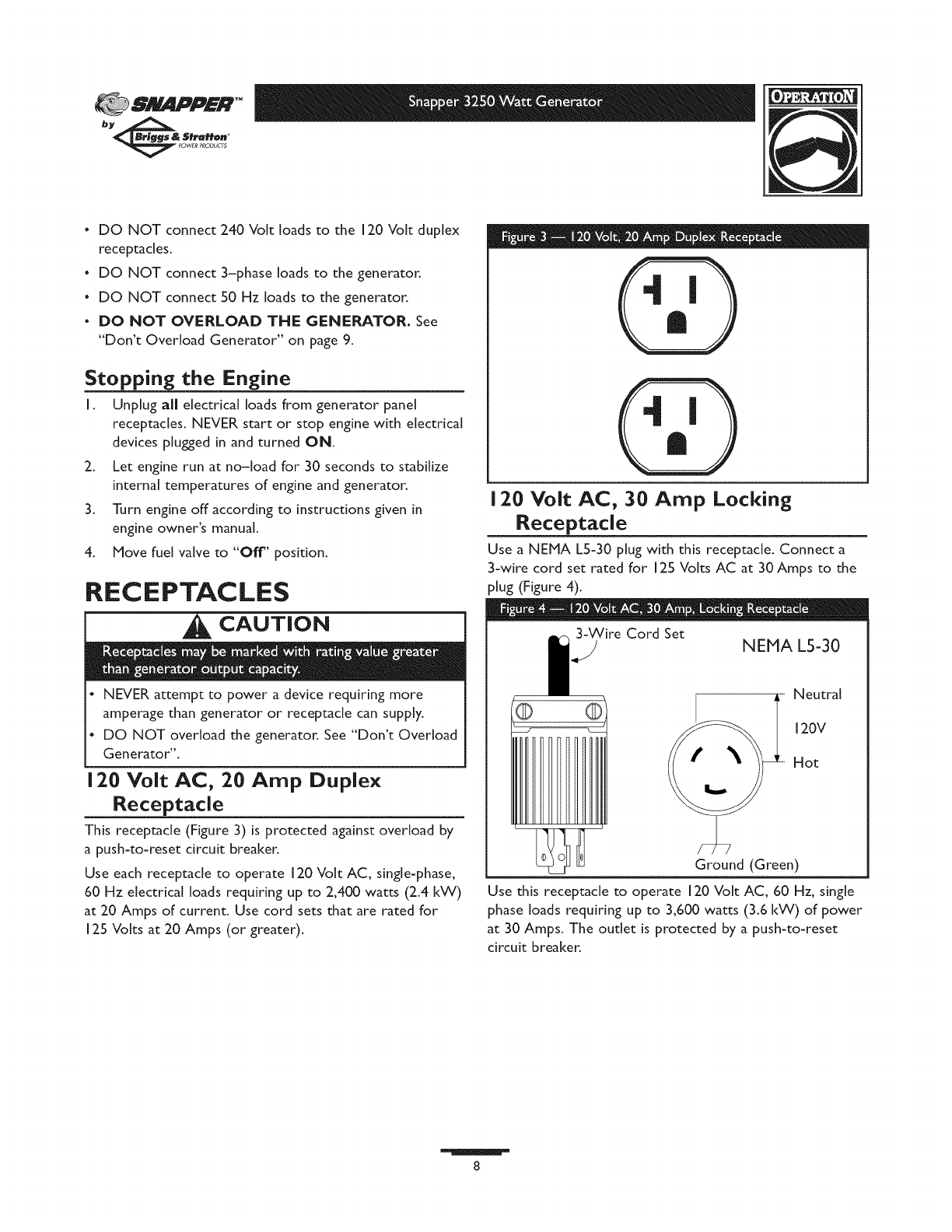
20 Volt AC, 20 Amp Duplex
Receptacle
This receptacle (Figure 3) is protected against oveHoad by
a push-to=reset circuit breaker.
Use each receptacle to operate 120 Volt AC, single=phase,
60 Hz electrical loads requiring up to 2,400 watts (2.4 kW)
at 20 Amps of current. Use cord sets that are rated for
125 Volts at 20 Amps (or greater).
20 Volt AC, 30 Amp Locking
Receptacle
Use a blEMA L5=30 plug with this receptacle. Connect a
3-wire cord set rated for 125 Volts AC at 30 Amps to the
plug (Figure 4).
3=Wire Cord Set NEMA L5=30
Neutral
120V
Hot
Z
Ground (Green)
Use this receptacle to operate 120 Volt AC, 60 Hz, single
phase loads requiring up to 3,600 watts (3.6 kW) of power
at 30 Amps. The outlet is protected by a push-to-reset
circuit breaker.
8
SA@I PER TM
bY B__r_s& Sfr_H@n
DON'T OVERLOAD
GENERATOR
acity
You must make sure your generator can supply enough
rated (running) and surge (starting) watts for the items you
will power at the same time. Follow these simple steps:
I. Select the items you will power at the same time.
2. Total the rated (running) watts of these items. This is
the amount of power your generator must produce to
keep your items running. See Figure 5.
3. Estimate how many surge (starting) watts you will
need. Surge wattage is the short burst of power
needed to start electric motor-driven tools or
appliances such as a circular saw or refrigerator.
Because not all motors start at the same time, total
surge watts can be estimated by adding only the
item(s) with the highest additional surge watts to the
total rated watts from step 2.
Example:
Tool or Appliance
Window Air
Conditioner
Refrigerator
Deep Freezer
Television
Light (75 Watts)
Rated (Running)
Watts
1200
800
500
500
75
3075 Total
RunningWatts
Total Rated (Running) Watts = 3075
Highest Additional Surge Watts = 1800
Total Generator Output Required = 4875
Additional Surge
(Starting) Watts
1800
[600
500
1800 Highest
Surge Watts
Power Management
To prolong the life of your generator and attached devices,
it is important to take care when adding electrical loads to
your generator. There should be nothing connected to the
generator outlets before starting it's engine. The correct
and safe way to manage generator power is to sequentially
add loads as follows:
I. With nothing connected to the generator, start the
engine as described in this manual
2. Plug in and turn on the first load, preferably the largest
load you have.
3. Permit the generator output to stabilize (engine runs
smoothly and attached device operates properly.
4. Plug in and turn on the next load.
5. Again, permit the generator to stabilize.
6. Repeat steps 4 and 5 for each additional load.
NEVER add more loads than the generator capacity. Take
special care to consider surge loads in generator capacity,
as described above.
: - ,o: ....... ,
Rated*
(Running)
Watts
Essentials
Light Bulb - 75 watt
Deep Freezer
Sump Pump
Refrigerator/Freezer - 18 Cu. Ft.
Water Well Pump - I/3 HP
Heating/Cooling
Window AC - [0,000 BTU
Window Fan
Furnace Fan Blower - 1/2 HP
Kitchen
Microwave Oven - [000 Watt
Coffee Maker
Electric Stove - Single Element
Hot Plate
Family Room
DVD/CD Player
VCR
Stereo Receiver
Color Television - 27"
Personal Computer w/[ 7" monitor
Other
Security System
AM/FM Clock Radio
Garage Door Opener - 1/2 HP
Electric Water Heater - 40 Gallon
DlY/Job Site
Quartz Halogen Work Light
Airless Sprayer - I/3 HP
Reciprocating Saw
Electric Drill - I/2 HP
Circular Saw - 7 I/4"
Miter Saw - I O"
Table Planer - 6"
Table Saw/Radial Arm Saw - I0"
Air Compressor - I-I/2 HP
Tool or Appliance
75
500 500
800 1200
800 1600
1000 2000
1200 1800
300 600
800 1300
1000
1500
1500
2500
100
100
450
500
80O
180
300
480 520
4000
1000
600 1200
960 960
1000 1000
1500 1500
1800 1800
1800 1800
2000 2000
2500 2500
Additional
Surge
(Starting)
Watts
*Wattages listed are approximate only. Check tool or
appliance for actual wattage.
9
SlULoPFR TM
bye& Stratton
V POWERPRODUCTS
SPECiFiCATiONS
Maximum Surge Watts ................ 4,500 Watts
Continuous Wattage Capacity .......... 3,250 Watts
Power Factor ................................ 1.0
Rated Maximum Continuous Load Current
At 120 Volts ....................... 27.1 Amps
Phase .................................. I=phase
Rated Frequency ....................... 60 Hertz
Shipping Weight .......................... 103 Ibs.
GENERAL MAINTENANCE
RECOMMENDATIONS
The Owner/Operator is responsible for making sure that
all periodic maintenance tasks are completed on a timely
basis; that all discrepancies are corrected; and that the unit
is kept clean and properly stored. NEVER operate a
damaged or defective generator.
NOTE: If equipped with inflatable tires, keep the air
pressure at the value marked on the tire or within I 5 and
40 psi.
Engine Maintenance
See engine owner's manual for instructions.
CAUTION
. Used motor oil has been shown to cause skin cancer in
certain laboratory animals.
. Thoroughly wash exposed areas with soap and water.
KEEP OUT OF REACH OF CHILDREN. DON'T
POLLUTE. CONSERVE RESOURCES. RETURN
USED OIL TO COLLECTION CENTERS.
Generator Maintenance
Generator maintenance consists of keeping the unit clean
and dry. Operate and store the unit in a clean dry
environment where it will not be exposed to excessive
dust, dirt, moisture or any corrosive vapors. Cooling air
slots in the generator must not become clogged with snow,
leaves or any other foreign material.
NOTE: DO NOT use a garden hose to clean generator.
Water can enter engine fuel system and cause problems. In
addition, if water enters generator through cooling air
slots, some of the water will be retained in voids and
cracks of the rotor and stator winding insulation. Water
and dirt buildup on the generator internal windings will
eventually decrease the insulation resistance of these
windings.
WARNING
WHEN ADJUSTING OR HAKING REPAIRS TO YOUR
GENERATOR
Disconnect the spark plug wire from the spark plug and place
the wire where it cannot contact spark plug.
Generator Cleaning
• Use a damp cloth to wipe exterior surfaces clean.
CAUTION
o
o
o
DO NOT expose generator to excessive moisture, dust, dirt,
or corrosive vapors.
DO NOT insert any objects through cooling slots.
Use a soft bristle brush to loosen caked on dirt or oil.
Use a vacuum cleaner to pick up loose dirt.
Use low pressure air (not to exceed 25 psi) to blow
away dirt. Inspect cooling air slots and opening on
generator. These openings must be kept clean and
unobstructed.
I0
SIU PER TM
bYB__r_s& Sfr_H@n
_ _w_R PRo_u_
STORAGE
The generator should be started at least once every seven
days and allowed to run at least 30 minutes. If this cannot
be done and you must store the unit for more than
30 days, use the following guidelines to prepare it for
storage.
Generator Storage
• Clean the generator as outlined in "Generator Cleaning".
• Check that cooling air slots and openings on generator
are open and unobstructed.
WARNING
. DO NOT place a storage cover over a hot generator.
. Let equipment cool for a sufficient time before placing the
cover on the equipment.
Engine Storage
See engine owner's manual for instructions.
Other Storage Tips
•To preventgum from forminginfuelsystem or on
essential carburetor parts, add fuel stabilizer into fuel
tank and fill with fresh gasoline. Run the unit for several
minutes to circulate the additive through the carburetor.
The unit and fuel can then be stored for up to
24 months. Fuel stabilizer can be purchased locally.
• DO NOT store gasoline from one season to another
unless it has been treated as described above.
•Replace fuel container if it starts to rust. Rust and/or dirt
in fuel can cause problems if it's used with this unit.
•Store in clean and dry area.
II
S PFR TM
bye& StPatton
V POWERPRODUCT5
TROUBLESHOOTING
Problem
Engine is running, but no AC or
DC output is available.
Engine runs good at no=load but
"bogs down" when loads are
connected.
Engine will not start; or starts and
runs rough.
Engine shuts down when running.
Engine lacks power.
Cause
1. One of the circuit breakers is
open,
2. Fault in generator.
3. Poor connection or defective cord
set.
4. Connected device is bad.
I. Short circuit in a connected load.
2, Generator is overloaded.
3. Shorted generator circuit.
Low oil level.
I. Out of gasoline.
2. Low oil level.
Load is too high.
Correction
1, Reset circuit breaker.
2. Contact Authorized service facility.
3. Check and repair.
4. Connect another device that is in
good condition.
I. Disconnect shorted electrical load.
2. See "Don't Overload Generator".
3. Contact Authorized service facility.
Fill crankcase to proper level or place
generator on level surface.
I. Fill fuel tank.
2. Fill crankcase to proper level or
place generator on level surface.
See "Don't OveHoad Generator".
[2

SNAPPER TM
bYB__r_s& Sfr_H@n
_ _w_R PRODU_S
NOTES
13
SAUIPPFR*"
bye& Stratton
V POWERPRODUCT5 ¢
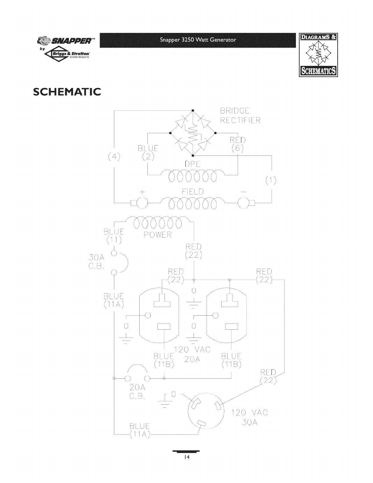
SCHEMATIC
/'\ /
)D D, B
j' k y
L 9 -_
/D _ D
\_ /,,
//
iqi i J_
_11 ......'
,\ ,,:4 /
\
[
.J/
: _' 2 ( )/",
\/
_-- ..... j. _---J
i
fA _ \
F¢f!!I-).....
/22 _
• ( ; ,;,, ....--
{............,)
"/...._,'U".....'
) i ./
/\ ,/
, , )
14
S#t#APPER TM
bYB__r_s& Sfr_H@n
_ FOW_RPRO_U_S
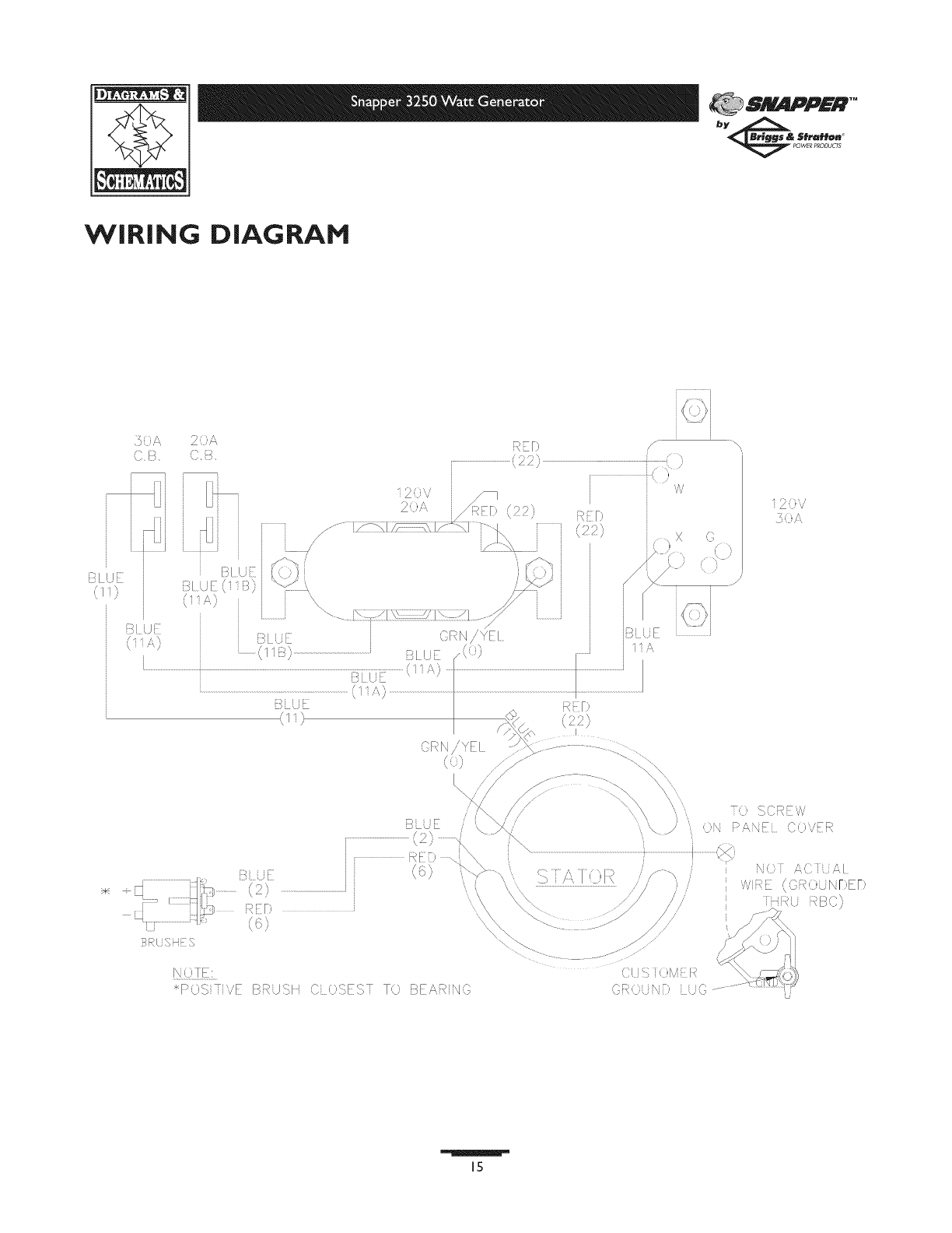
WiRiNG DIAGRAH
r i
BL,IE
i i
I
:i .1
+ q ......................................I_oI_''_.............
iI
BRUS E5
__LUF
.................................................._ ..............._
,.RE_
Ji
J
N TE:
*P,:,STV'E BFR.J"31 C)i:,_3E'.;T
\\
TO SSRE'iv
\ .... ,"\J 0 PA C,,v'FR
,:i; A,,%i a,I....
........'1-_) .... ', t,,'O::t,:)UNF)EF)
\iI ........ iI:_L
TO
J
,\
BEA,RiNC
15
SNJKoPFR TM
bye& Stratton
V POWERPRODUCT5
I
2J_
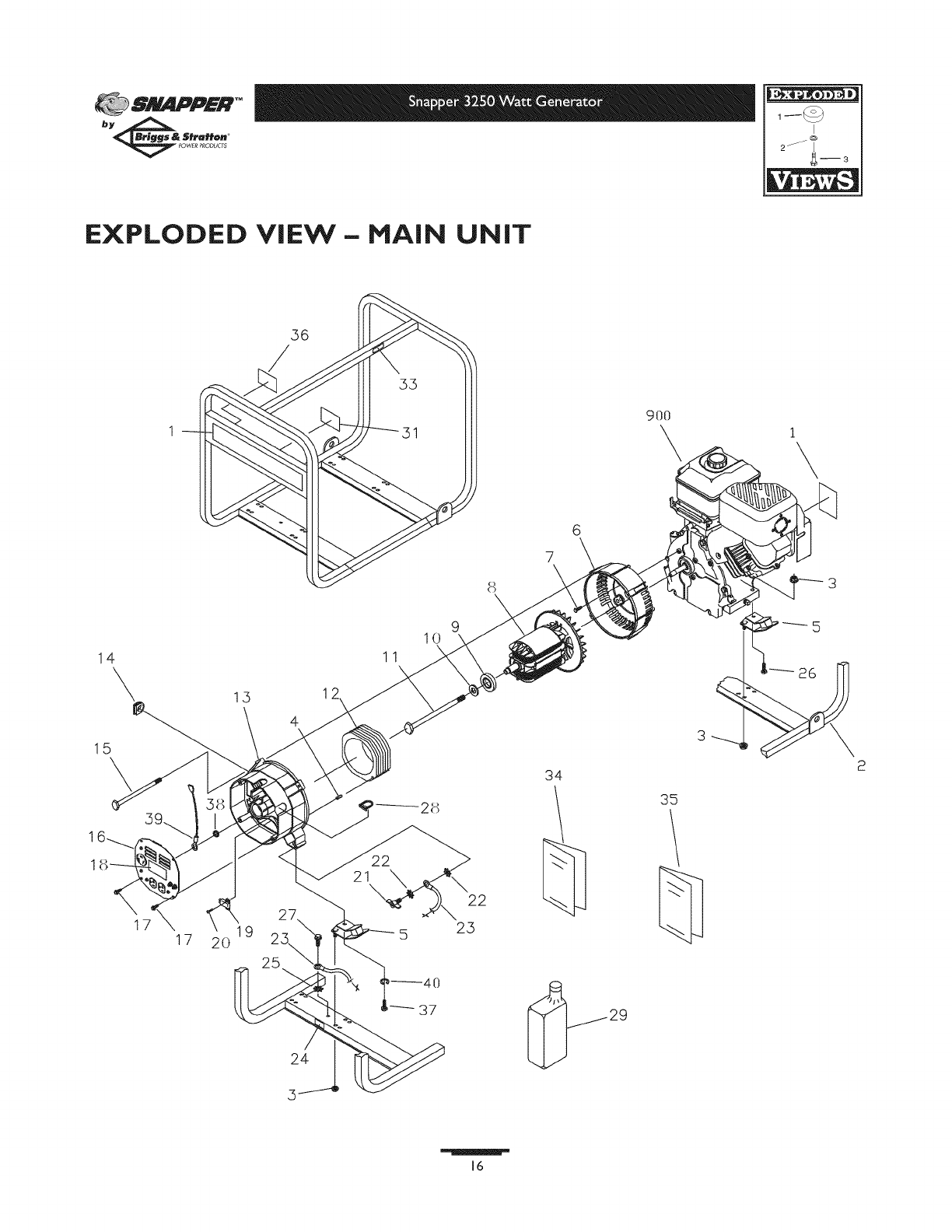
EXPLODED ViEW- HAIN UNiT
14\
15\
1
1
17 17 2O
13
\
19
36
10
11
21 \
22
23
6
7
34
900
\1\
24
3
29
16
I
2J_
4--3
SA MDPE'R TM
bYB__r_s& Sfr_H@n
_ _w_R PRo_u_
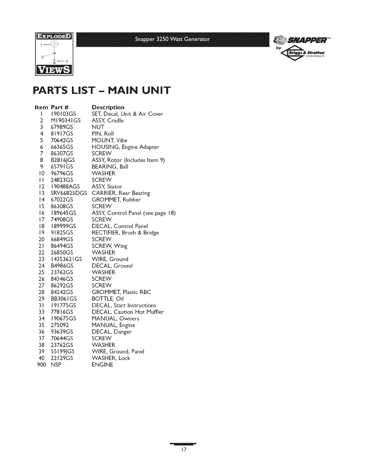
PARTS LiST- HAIN UNiT
_tem
I
2
3
4
5
6
7
8
9
0
I
2
3
4
5
6
7
8
9
2O
21
22
23
24
25
26
27
28
29
31
33
34
35
36
37
38
39
4O
9OO
Part # Description
190103GS SET, Decal, Unit &Air Cover
M 190341GS ASSY, Cradle
67989GS NUT
81917GS PIN, Roll
70642GS MOUNT, V[be
66365GS HOUSING, Engine Adapter
86307GS SCREW
B2816JGS ASSY, Rotor (Includes Item 9)
65791GS BEARING, Ball
96796GS WASHER
24823GS SCREW
190488AGS ASSY, Stator
SRV66825DGS CARRIER, Rear Bearing
67022GS GROMMET, Rubber
86308GS SCREW
189645GS ASSY, Control Panel (see page 18)
74908GS SCREW
189999GS DECAL, Control Panel
91825GS RECTIFIER, Brush &Bridge
66849GS SCREW
86494GS SCREVV,Wing
26850GS WASHER
14353621GS WIRE, Ground
B4986GS DECAL, Ground
23762GS WASHER
84346GS SCREW
86292GS SCREW
84242GS GROMMET, Plastic RBC
BB3061GS BOTTLE, Oil
191775GS DECAL, Start Instructions
77816GS DECAL, Caution Hot Muffler
190675GS MANUAL, Owners
275092 MANUAL, Engine
93639GS DECAL, Danger
70644GS SCREW
23762GS WASHER
55199JGS WIRE, Ground, Panel
22129GS WASHER, Loci<
NSP ENGINE
17
SAUIPPFR TM
bye& Stratton
V POWERPRODUCT5
I
2J_
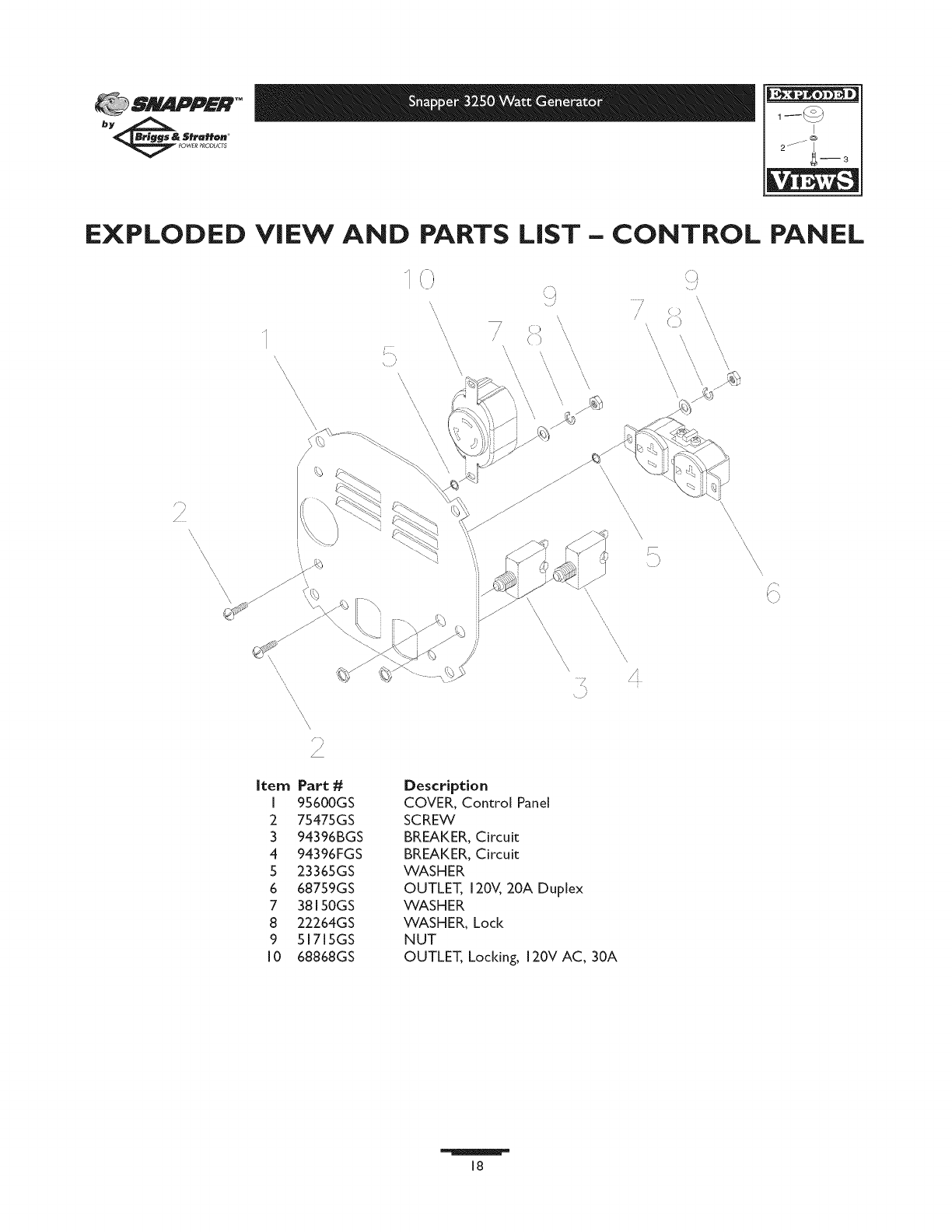
EXPLODED ViEW AND PARTS LiST - CONTROL PANEL
, J
/
/\,\
', \
\\ ',\ \\
\ ',
\,
\
\
'_\\\\
\\
\\\\\\
\\\\\
F_
_tem
I
2
3
4
5
6
7
8
9
I0
Part #
95600GS
75475GS
94396BGS
94396FGS
23365GS
68759GS
38150GS
22264GS
51715GS
68868GS
Description
COVER, Control Panel
SCREW
BREAKER, Circuit
BREAKER, Circuit
WASHER
OUTLET, 120V, 20A Duplex
WASHER
WASHER, Lock
NUT
OUTLET, Locking, 120V AC, 30A
\\\\
\\\\\\
18
I
2J_4--3
SA_MDPE'R TM
bYB__r_s& Sfr_H@n
_ _w_R PRo_u_
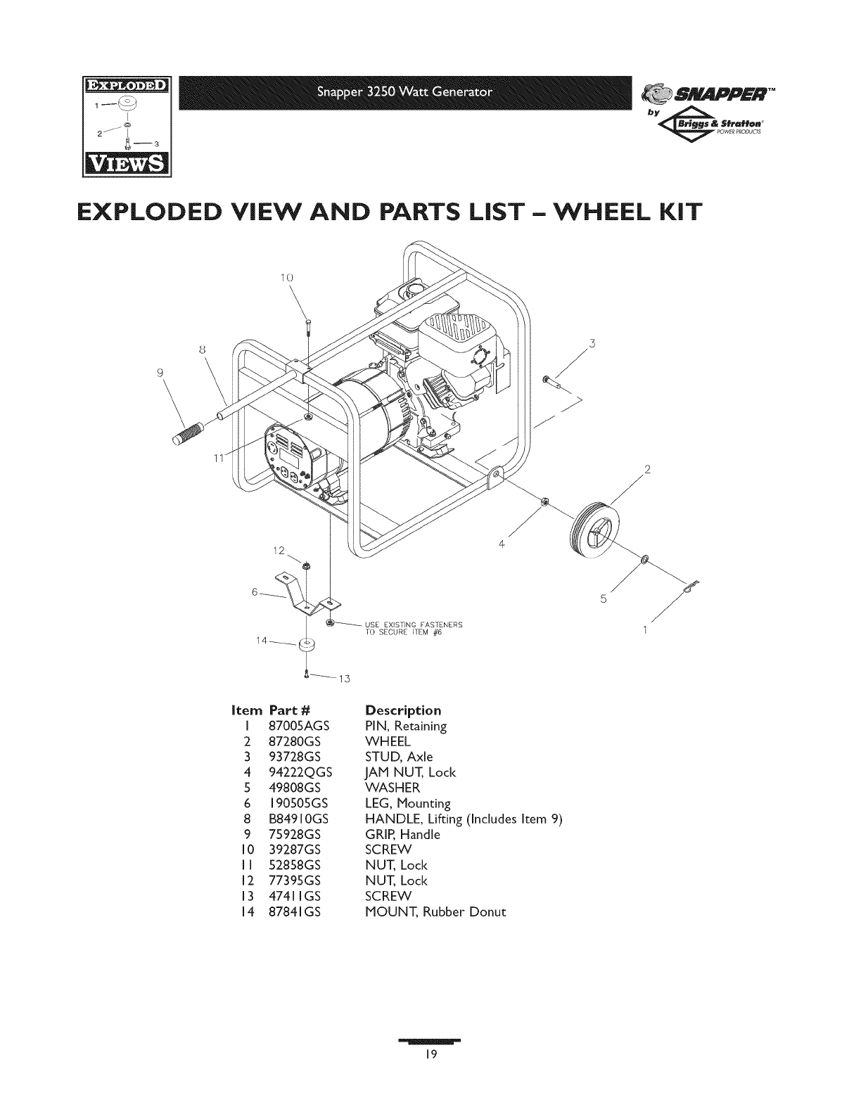
EXPLODED ViEW AND PARTS LiST- WHEEL KiT
10
_tem
I
2
3
4
5
6
8
9
I0
II
12
13
14
2
'_15
Part #
87005AGS
87280GS
93728GS
94222QGS
49808GS
190505GS
B84910GS
75928GS
39287GS
52858GS
77395GS
4741 I GS
87841GS
Description
PIN, Retaining
WHEEL
STUD, Axle
JAM NUT, Lock
WASHER
LEG, Mounting
HANDLE, Lifting (Includes Item 9)
GRIR Handle
SCREW
NUT, Lock
NUT, Lock
SCREW
MOUNT, Rubber Donut
19
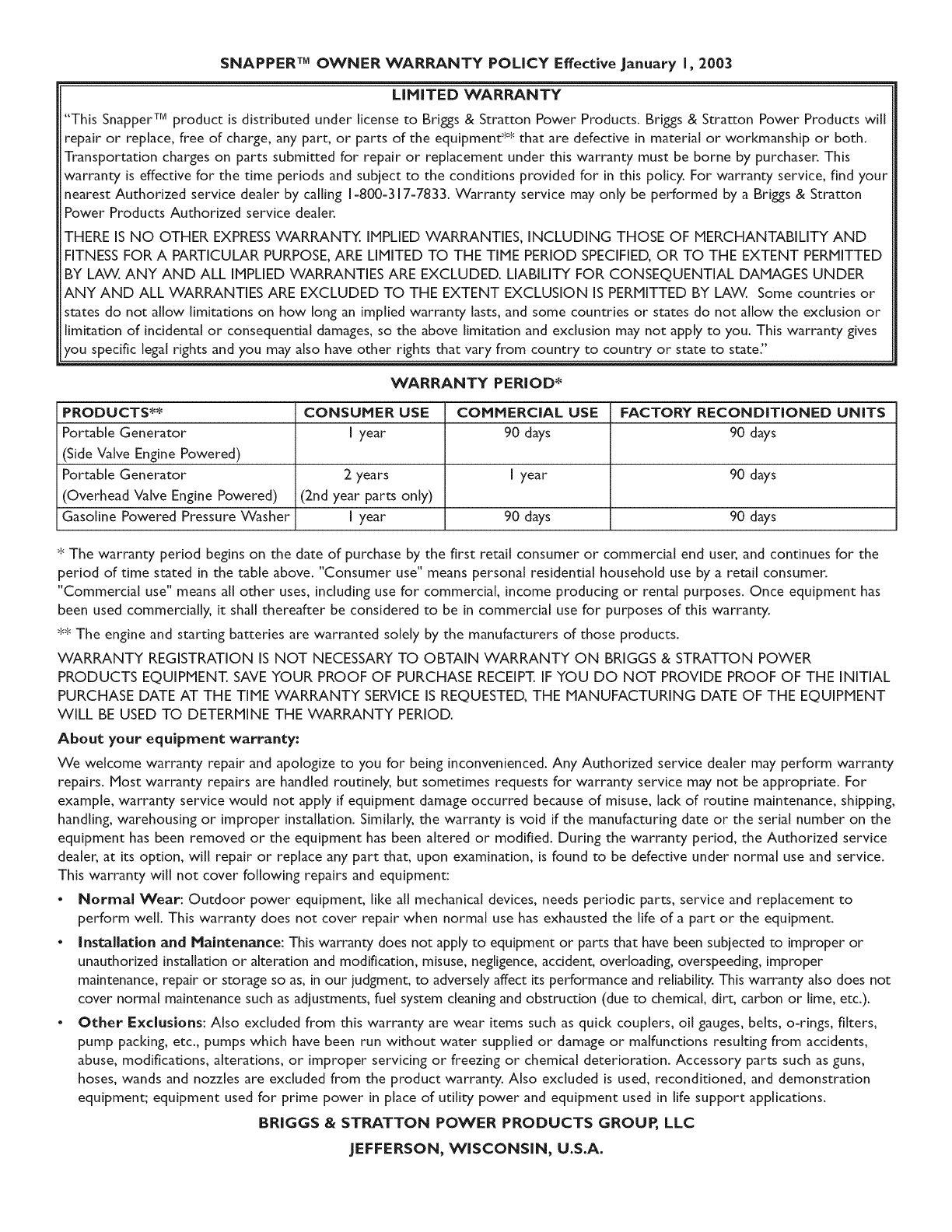
SNAPPER TM OWNER WARRANTY POLICY Effective January I, 2003
LIMITED WARRANTY
"This Snapper TM product is distributed under license to Brigs &Stratton Power Products. Briggs & Stra_on Power Products will
repair or replace, free of charge, any part, or parts of the equipment _ that are defective in material or workmanship or both.
Transportation charges on parts submitted for repair or replacement under this warranty must be borne by purchaser. This
warranty is effective for the time periods and subject to the conditions provided for in this policy. For warranty service, find your
nearest Authorized service dealer by calling [-800-3 [ 7-7833. Warranty service may only be performed by a Brigs & Stratton
Power Products Authorized service dealer.
THERE IS NO OTHER EXPRESSWARRANTY. IMPLIED WARRANTIES, INCLUDING THOSE OF MERCHANTABILITY AND
FITNESSFOR A PARTICULARPURPOSE,ARE LIMITED TO THE TIME PERIOD SPECIFIED,OR TO THE EXTENT PERMITTED
BY LAW. ANY AND ALL IMPLIED WARRANTIES ARE EXCLUDED. LIABILITY FOR CONSEQUENTIAL DAMAGES UNDER
ANY AND ALL WARRANTIES ARE EXCLUDED TO THE EXTENT EXCLUSION IS PERMITTEDBY LAW. Some countries or
states do not allow limitations on how long an implied warranty lasts,and some countries or states do not allow the exclusion or
limitation of incidental or consequential damages,so the above limitation and exclusion may not apply to you. This warranty gives
you specific legalrights and you may also have other rights that vary from country to country or state to state"
WARRANTY PERIOD*
PRODUCTS** CONSUMER USE COMMERCIAL USE FACTORY RECONDiTiONED UNITS
Portable Generator I year 90 days 90 days
(Side Valve Engine Powered)
Portable Generator 2 years I year 90 days
(Overhead Valve Engine Powered) (2nd year parts only)
Gasoline Powered Pressure Washer I year 90 days 90 days
_ The warranty period begins on the date of purchase by the first retail consumer or commercial end user, and continues for the
period of time stated in the table above. "Consumer use" means personal residential household use by a retail consumer.
"Commercial use" means all other uses, including use for commercial, income producing or rental purposes. Once equipment has
been used commercially, it shall thereafter be considered to be in commercial use for purposes of this warranty.
_ The engine and starting batteries are warranted solely by the manufacturers of those products.
WARRANTY REGISTRATION IS NOT NECESSARY TO OBTAIN WARRANTY ON BRIGGS & STRATTON POWER
PRODUCTS EQUIPMENT. SAVE YOUR PROOF OF PURCHASE RECEIPT. IF YOU DO NOT PROVIDE PROOF OF THE INITIAL
PURCHASE DATE AT THE TIME WARRANTY SERVICE IS REQUESTED, THE MANUFACTURING DATE OF THE EQUIPMENT
WILL BE USED TO DETERMINE THE WARRANTY PERIOD.
About your equipment warranty:
We welcome warranty repair and apologize to you for being inconvenienced. Any Authorized service dealer may perform warranty
repairs. Most warranty repairs are handled routinely, but sometimes requests for warranty service may not be appropriate. For
example, warranty service would not apply if equipment damage occurred because of misuse, lack of routine maintenance, shipping,
handling, warehousing or improper installation. Similarly, the warranty is void if the manufacturing date or the serial number on the
equipment has been removed or the equipment has been altered or modified. During the warranty period, the Authorized service
dealer, at its option, will repair or replace any part that, upon examination, is found to be defective under normal use and service.
This warranty will not cover following repairs and equipment:
• Normal Wear: Outdoor power equipment, like all mechanical devices, needs periodic parts, service and replacement to
perform well. This warranty does not cover repair when normal use has exhausted the life of a part or the equipment.
• installation and Maintenance: This warranty does not apply to equipment or parts that have been subjected to improper or
unauthorized installation or alteration and modification, misuse, negligence, accident_ overloading, overspeeding, improper
maintenance, repair or storage so as, in our judgment, to adversely affect its performance and reliability. This warranty also does not
cover normal maintenance such as adjustments, fuel system cleaning and obstruction (due to chemical, dirt, carbon or lime, etc.).
• Other Exclusions: Also excluded from this warranty are wear items such as quick couplers, oil gauges, belts, o-rings, filters,
pump packing, etc., pumps which have been run without water supplied or damage or malfunctions resulting from accidents,
abuse, modifications, alterations, or improper servicing or freezing or chemical deterioration. Accessory parts such as guns,
hoses, wands and nozzles are excluded from the product warranty. Also excluded is used, reconditioned, and demonstration
equipment; equipment used for prime power in place of utility power and equipment used in life support applications.
BRIGGS & STRATTON POWER PRODUCTS GROUP, LLC
JEFFERSON, WiSCONSiN, U.S.A.
