SOLiD 19P85C70L21A Repeater User Manual
SOLiD, Inc. Repeater
UserManual.wiki
>
SOLiD
>
19P85C70L21A User Manual
>
Manual 1
Contents
1.
Manual 1
2.
Manual 2
3.
User Manual
Manual 1
Navigation menu
Upload a User Manual
Namespaces
Wiki Guide
HTML
PDF
Info
Views
User Manual
Discussion / Help
Navigation
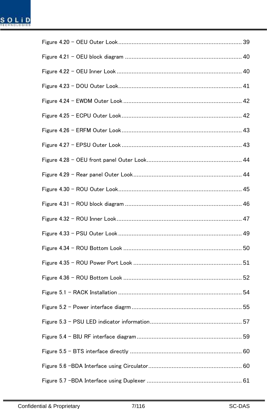
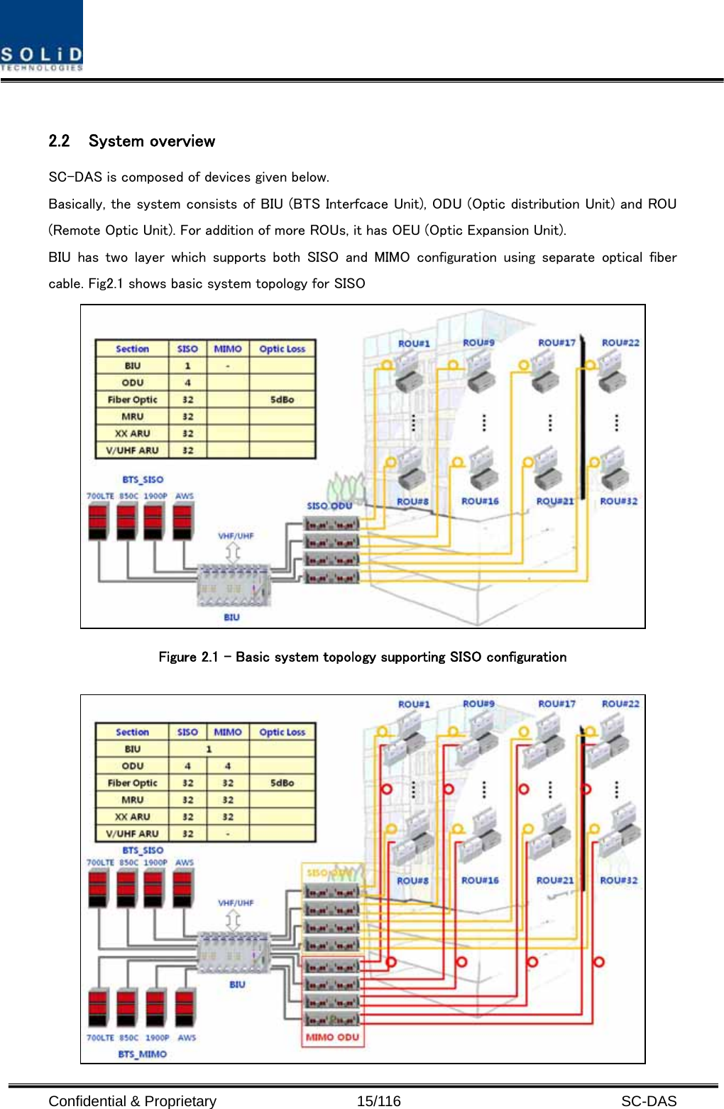
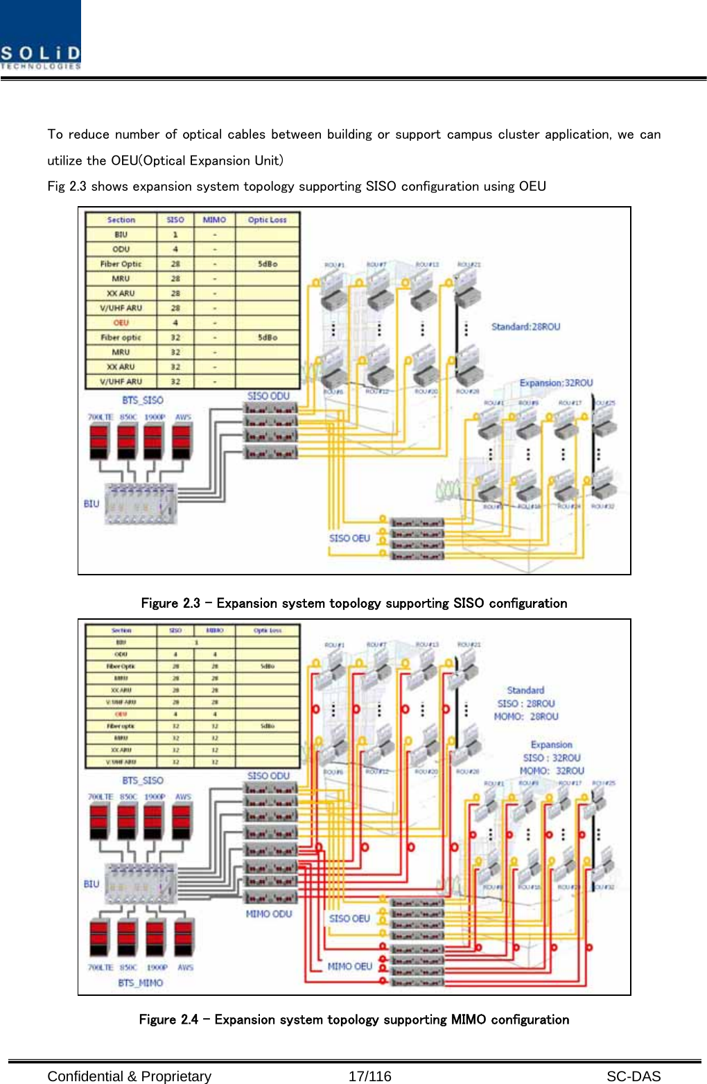
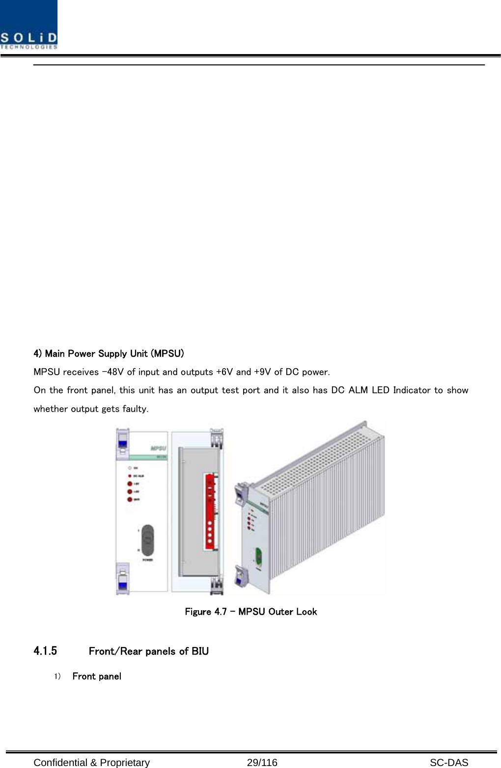
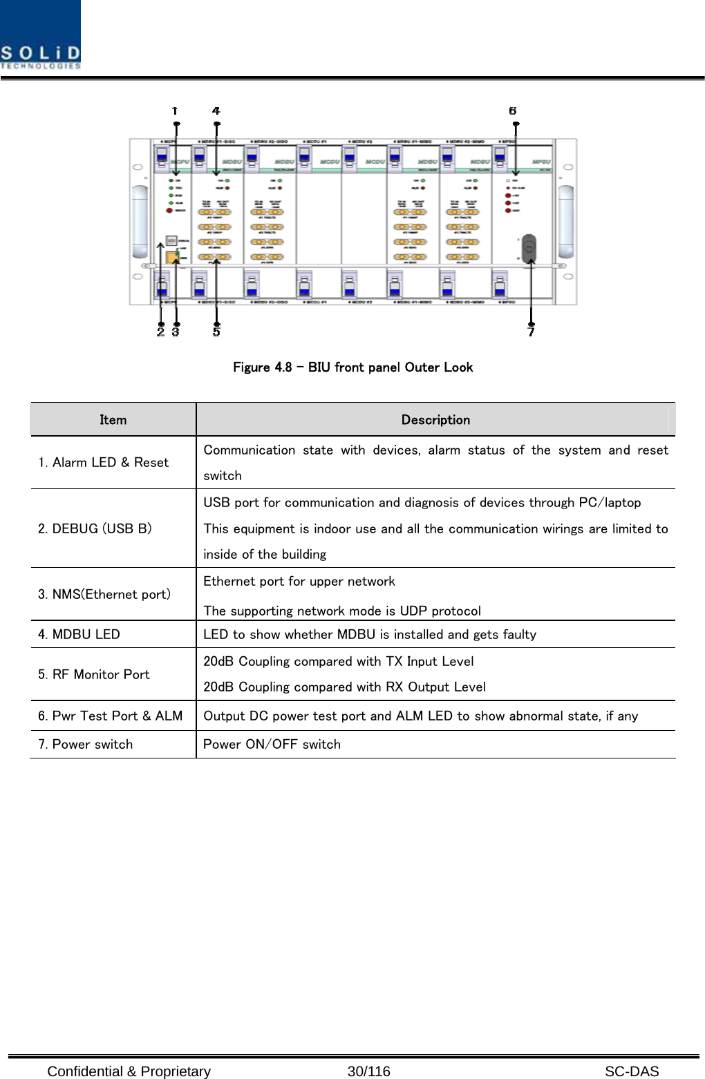
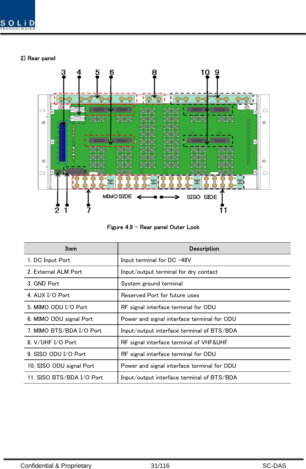
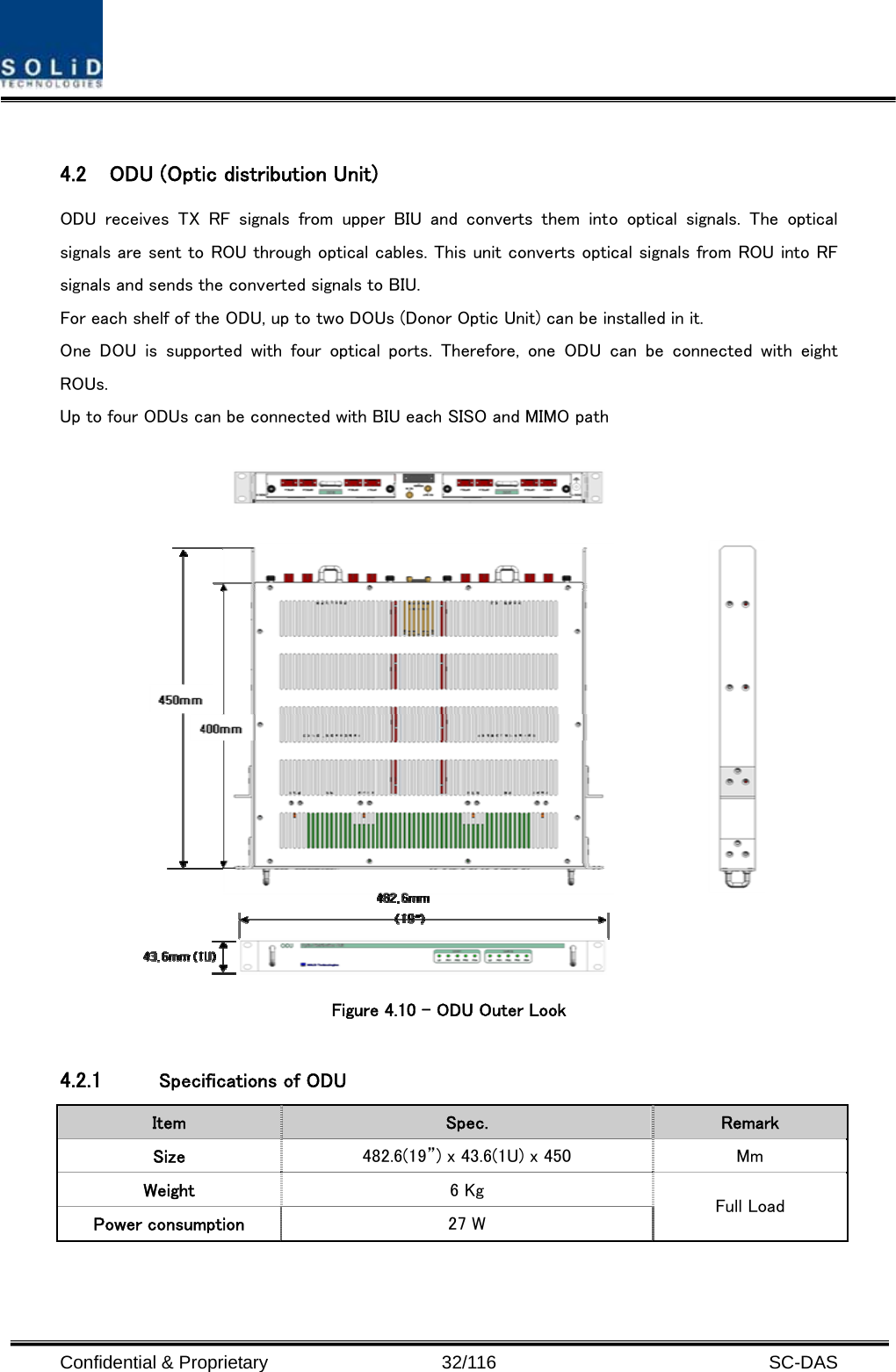
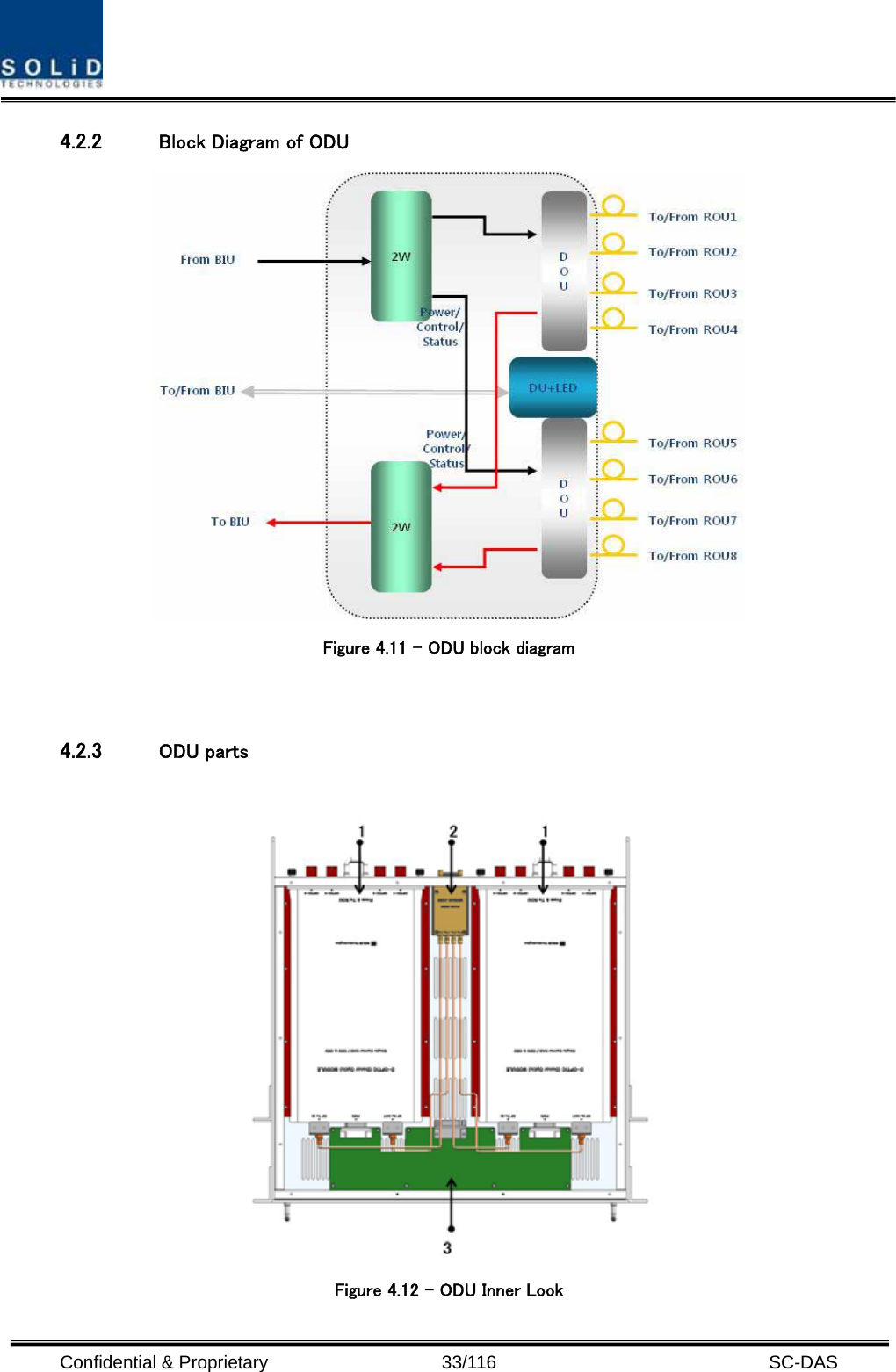
![Confidential & Proprietary 19/116 SC-DAS 3.1 System specifications 3.1.1 Physical Specifications Parameter BIU ODU OEU MRU ARU RF Connectors 4 SMA pairs(TX,RX) per MDBU 2 SMA - 1 N-type 2SMA :optical 2SMA :RF 2SMA :optical 2SMA :RF External Alarm connector (Dry contacts) TB: 4pcs for output TB: 3pcs for input - - - - Serial Interface connector 1 USB(B) type 1 USB(B) type 1 USB(B) type 1 USB(B) type Fiber connector - 8pcs, SC/APC for ROU 1 SC/APC for ODU 8 SC/APC for ROU 1 SC/APC for ODU - LED Alarm and Status Indicator MDBU Status z Power status z ALM status MCPU z Power status z TX Comm z RX Comm z ALM status MPSU z Power status z DC ALM status DOU1 Status z LD status z PD1/2/3/4 status DOU2 Status z LD status z PD1/2/3/4 status EWDM Status z LD status z PD status DOU1 Status z LD status z PD1/2/3/4 status DOU2 Status z LD status z PD1/2/3/4 status System status z Power status z TX1 Comm z RX1 Comm z TX2 Comm z RX2 Comm z ALM status System status z Power status z TX Comm z RX Comm z ALM status z Opt status System status z Power status z TX Comm z RX Comm z ALM status AC Power - - Normal Range: 120VAC 50/60Hz Operating range 108~132VAC,50/60Hz Same left side DC Power Normal range: -48 VDC Operating range: -40.8 ~ -57.6VDC Be provided by BIU Normal: -48 VDC Operating range: -40.8 ~ -57.6VDC Same to left side Power consumption SISO Mode : 162W (Including SISO ODU 4EA) MIMO Mode : 315W (Including SISO ODU 4EA+MIMO ODU 4EA) 28W (Including DOU2EA)40W (Including DOU2EA) 50W for dual band 40W for dual band Enclosure Dimensions 482.6(19”) x 221.5(5U) x 450 482.6(19”) x 43.6(1U) x 450 482.6(19”) x 88.1(2U) x 450 300 x 200 x 258 300 x 200 x 258 Weight[Full Load] 26.2Kg 6Kg 9.6Kg 6.6Kg 6.8Kg](https://usermanual.wiki/SOLiD/19P85C70L21A.Manual-1/User-Guide-1474105-Page-19.png)
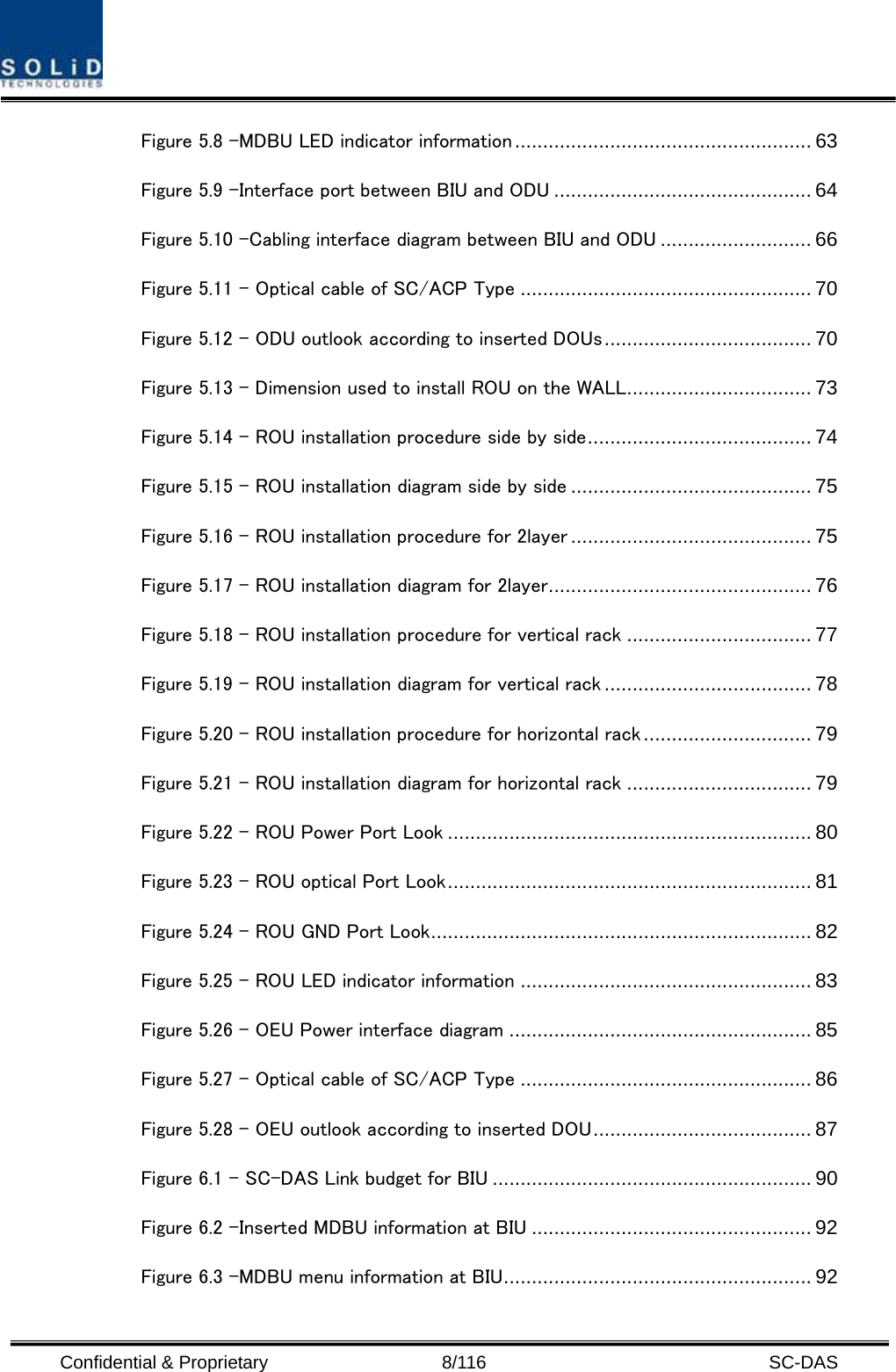
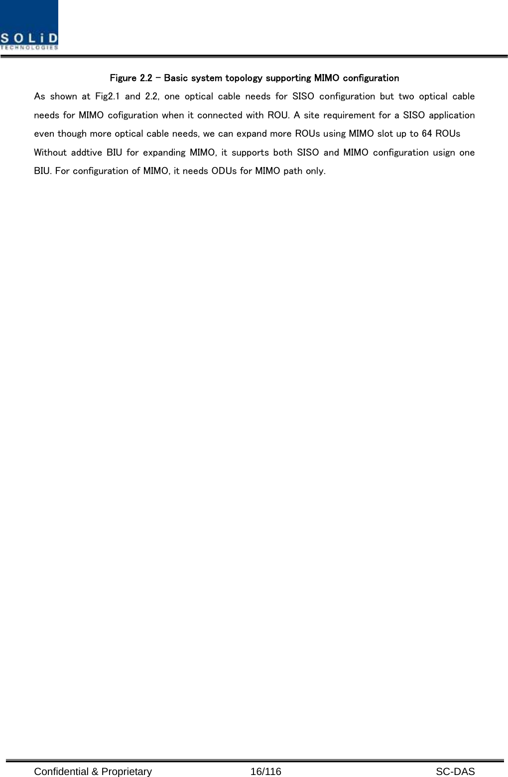
![Confidential & Proprietary 28/116 SC-DAS Figure 4.6 – MCPU Outer Look In the Main Central Processor Unit, a lithium battery is installed for RTC (Real Time Control) function. CAUTION RISK OF EXPLOSION IF BATTERY IS REPLACED BY AN INCORRECT TYPE DIPOSE OF USED BATTERIES ACCORDING TO THE INSTRUCTIONS [INSTRUCTION] The equipment and accessories including inner lithium battery are to be disposed of safely after the life span of them and national regulation must be observed. Do not attempt to replace the lithium battery unless service personnel confirmation has first been obtained, to avoid any risk of explosion.](https://usermanual.wiki/SOLiD/19P85C70L21A.Manual-1/User-Guide-1474105-Page-28.png)