User Manual
Confidential&Proprietary1/122 SC‐DAS
SC‐DAS
InstallationandOperationManual
DocumentReference:
Version:V3.0
DocumentStatus:Release3
IssueDate:January.06,2012
Author:KyungEunHan
Department:R&DDivisionTeam3
AuthorizingManager: YoungshinYeo

Confidential&Proprietary2/122 SC‐DAS
REVISIONHISTORY
VersionIssueDateNo.of
PagesInitialsDetailsofRevisionChanges
V1.0April.11,2011 Original
V2.0Dec.08,2011 AddSprintband
V3.0Jan.06,2012
TechnicalSupport
SOLiDserialnumbersmustbeavailabletoauthorizetechnicalsupportand/ortoestablishareturn
authorizationfordefectiveunits.Theserialnumbersarelocatedonthebackoftheunit,aswellason
theboxinwhichtheyweredelivered.Additionalsupportinformationmaybeobtainedbyaccessing
theSOLiDTehcnology,Inc.websiteatwww.st.co.krorsendemailatsjkim@st.co.kr
ThismanualisproducedbyGlobalBusinessDivisionBusinessTeam1.PrintedinKorea.

Confidential&Proprietary3/122 SC‐DAS
Contents
Section1 Safety&CertificationNotice ...................................................................... 14
Section2 SystemOverview ....................................................................................... 17
2.1 Generaloverview ............................................................................................ 18
2.2 Systemoverview............................................................................................. 20
Section3 SystemSpecifications ................................................................................ 23
3.1 Systemspecifications...................................................................................... 24
3.1.1 PhysicalSpecifications .............................................................................. 24
3.1.2 OpticalwavelengthandLaserpower......................................................... 27
3.1.3 Environmentalspecifications .................................................................... 27
3.1.4 AvailableFrequencyBands........................................................................ 27
3.1.5 BandSpecifications................................................................................... 28
Section4 SystemConfigurationandFunctions........................................................... 30
4.1 BIU(BTSInterfaceUnit) .................................................................................. 31
4.1.1 BIUSpecifications..................................................................................... 31
4.1.2 BIUblockdiagram..................................................................................... 32
4.1.3 BIUassemblies.......................................................................................... 33
4.1.4 SubAssemblyDescription ......................................................................... 34
4.1.5 BIUfront/rearpaneloverview................................................................... 39
4.2 ODU(OpticdistributionUnit) .......................................................................... 43
4.2.1 ODUspecifications.................................................................................... 43
4.2.2 ODUblockdiagram ................................................................................... 44
4.2.3 ODUassemblies ........................................................................................ 44
4.2.4 SubAssemblydescription ......................................................................... 46
4.2.5 ODUfront/rearpaneloverview ................................................................. 47
4.2.6 ODUInterfacewithBIU............................................................................. 48
4.3 OEU(OpticExpansionUnit)............................................................................. 51
4.3.1 SpecificationsofOEU................................................................................ 51
4.3.2 OEUblockdiagram ................................................................................... 52
4.3.3 OEUassemblies......................................................................................... 53
4.3.4 SubAssemblydescription ......................................................................... 54
4.3.5 OEUfront/rearpaneloverview.................................................................. 57
4.4 ROU(RemoteOpticUnit) ................................................................................ 58

Confidential&Proprietary4/122 SC‐DAS
4.4.1 ROUspecifications.................................................................................... 60
4.4.2 ROUblockdiagram ................................................................................... 61
4.4.2.1 CombinationofMRU1900PCS+850C/ARU700LTE+AWS‐1........................... 61
4.4.2.2 CombinationofMRU1900PCS/ARU900I+800I ........................................... 62
4.4.3 ROUassemblies ........................................................................................ 63
4.4.3.1 CombinationofMRU1900PCS+850C/ARU700LTE+AWS‐1........................... 63
4.4.3.2 CombinationofMRU1900PCS/ARU900I+800I ........................................... 65
4.4.4 SubAssemblydescription ......................................................................... 68
4.4.5 BottomofROU ......................................................................................... 70
4.4.6 TopofROU ............................................................................................... 72
4.4.6.1 CombinationofMRU1900PCS+850C/ARU700LTE+AWS‐1............................ 72
4.4.6.2 CombinationofMRU1900PCS+850C/ARU700LTE+AWS‐1............................ 72
Section5 SystemInstallation&Operation ................................................................. 75
5.1 BIUInstallation ............................................................................................... 77
5.1.1 BIUShelfInstallation....................................................................................... 77
5.1.2 BIUPowerCabling .......................................................................................... 78
5.1.3 BIU/RFinterface.............................................................................................. 82
5.1.4 MDBUinstallation ........................................................................................... 87
5.1.5 ODUInterface ................................................................................................. 89
5.1.6 BIUpowerconsumption.................................................................................. 93
5.2 ODUInstallation.............................................................................................. 94
5.2.1 ODUShelfInstallation ..................................................................................... 94
5.2.2 ODUPowerCabling......................................................................................... 94
5.2.3 ODUOpticCabling .......................................................................................... 94
5.2.4 DOUinstallation.............................................................................................. 95
5.2.5 ODUPowerconsumption ................................................................................ 97
5.3 ROUInstallation.............................................................................................. 98
5.3.1 ROUEnclosureinstallation .............................................................................. 98
5.3.2 ROUPowerCabling....................................................................................... 106
5.3.3 OpticalCabling.............................................................................................. 108
5.3.4 GNDTerminalConnection ............................................................................. 109
5.3.5 CoaxialcableandAntennaConnection .......................................................... 109
5.3.6 LEDexplanationonROU ............................................................................... 110
5.3.7 ROUPowerconsumption .............................................................................. 110
5.3.8 CableconnectionbetweenMRUandARU.......................................................111
5.4 OEUInstallation ............................................................................................ 113

Confidential&Proprietary5/122 SC‐DAS
5.4.1 OEUchassisinstallation................................................................................. 113
5.4.2 OEUPowerCabling ....................................................................................... 113
5.4.3 OEUOpticCabling......................................................................................... 115
5.4.4 DOUinstallationwithanOEU........................................................................ 116
5.4.5 OEUPowerConsumption .............................................................................. 117
Section6 Operation................................................................................................ 119
6.1 BIUOverview................................................................................................ 120
6.1.1 BIU ............................................................................................................... 120
6.1.2 BIUTXparameters ........................................................................................ 120
6.1.3 BIURXparameters........................................................................................ 128
6.1.4 BIULogicSequenceDiagram......................................................................... 129
6.1.5 InteractionwiththeBIU ................................................................................ 133
6.2 ROUOverview .............................................................................................. 135
6.2.1 ROUOperation.............................................................................................. 135
6.3 OEUOperation.............................................................................................. 144
6.3.1 OEUOperation.............................................................................................. 144
Section7 Additivefunctions.................................................................................... 150
7.1 Shutdownfunction(TXoutputshutdown) .................................................... 151
7.2 TotalPowerLimitfunction(TXOutputALC) .................................................. 152
7.3 AutomaticOutputpowersettingfunction(TXOutputAGC)........................... 152
7.4 InputpowerAGCfunction(TXInputAGC) ..................................................... 152
7.5 Inputpowerlimitfunction(TXInputALC) ..................................................... 153
7.6 Opticallosscompensation............................................................................. 154

Confidential&Proprietary6/122 SC‐DAS
Figures
Figure2.1–BasicsystemtopologysupportingSISOconfiguration ..................... 20
Figure2.2–BasicsystemtopologysupportingMIMOconfiguration .................. 21
Figure2.3–ExpansionsystemtopologysupportingSISOconfiguration............. 22
Figure2.4–ExpansionsystemtopologysupportingMIMOconfiguration .......... 23
Figure4.1–BIUfrontandsideviews................................................................. 31
Figure4.2–BIUblockdiagram ......................................................................... 32
Figure4.3–BIUmountingdiagram................................................................... 33
Figure4.4–MDBUataglance.......................................................................... 35
Figure4.5–MCDUataglance .......................................................................... 36
Figure4.6–MCPUataglance .......................................................................... 37
Figure4.7–MPSUataglance .......................................................................... 39
Figure4.8–BIUfrontpanelview...................................................................... 39
Figure4.9–Rearpanelview............................................................................. 41
Figure4.10–ODUataglance ........................................................................... 43
Figure4.11–ODUblockdiagram....................................................................... 44
Figure4.12–ODUInternalView ....................................................................... 45
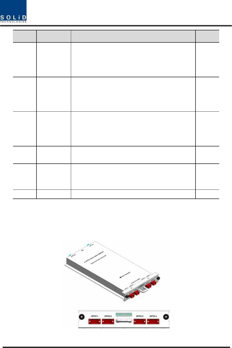
Figure4.13–DOUataglance ........................................................................ 46
Figure4.14–2WayDividerataglance............................................................... 47
Figure4.15–ODUfrontpanelview................................................................... 47
Figure4.16–ODURearpanelview ................................................................... 48
Figure4.17BIU/ODUinterface .......................................................................... 49

Confidential&Proprietary7/122 SC‐DAS
Figure4.18–BIU/ODUInterfacerearview ........................................................ 50
Figure4.19–BIU/ODUinterfacedetails............................................................. 50
Figure4.20–OEUataglance ........................................................................... 51
Figure4.21–OEUblockdiagram....................................................................... 52
Figure4.22–OEUinternalview ........................................................................ 53
Figure4.23–DOUataglance........................................................................... 54
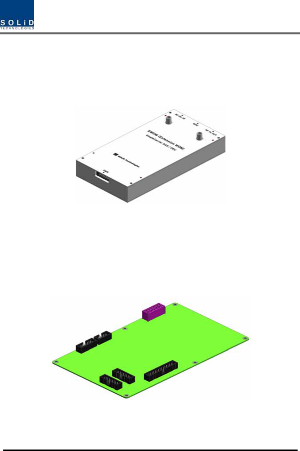
Figure4.24–EWDMataglance........................................................................ 55
Figure4.25–ECPUataglance.......................................................................... 55
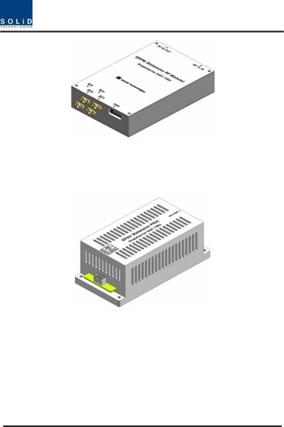
Figure4.26–ERFMataglance ......................................................................... 56
Figure4.27–EPSUataglance .......................................................................... 56
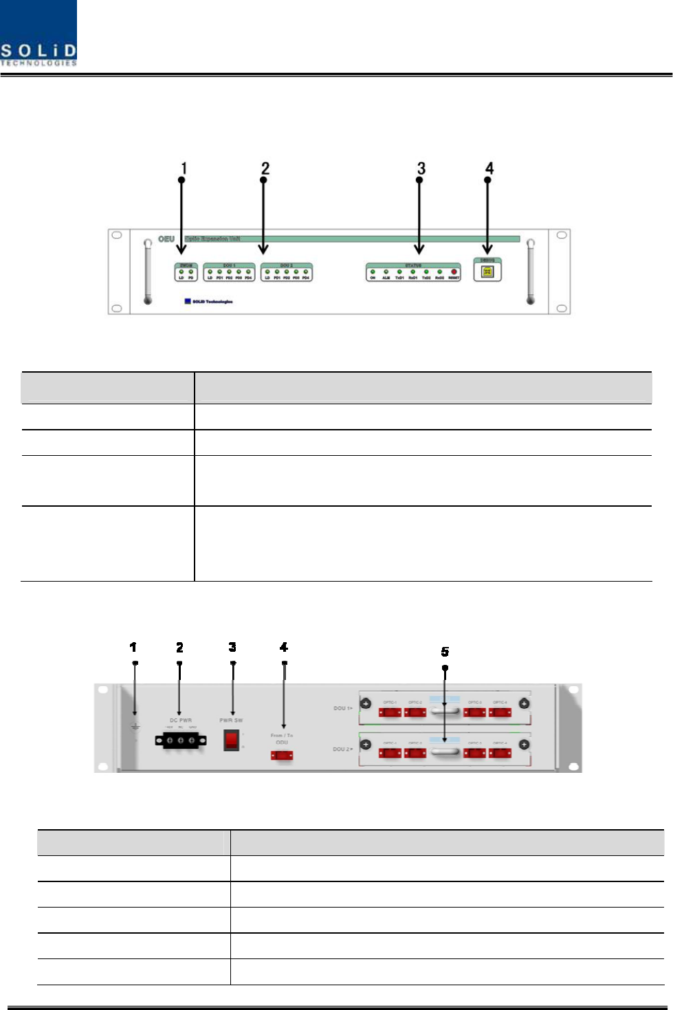
Figure4.28–OEUfrontpanelview................................................................... 57
Figure4.29–Rearpanelview........................................................................... 57
Figure4.30–ROUataglance........................................................................... 59
Figure4.31–ROUblockdiagramforMRU1900PCS+850CandARU700LTE+AWS‐1
................................................................................................................ 61
Figure4.32–ROUblockdiagramforMRU1900PCSandARU900I+800I............ 62
Figure4.33–ROUinternalviewforMRU1900PCS+850CandARU700LTE+AWS‐1
................................................................................................................ 64
Figure4.34–ROUinternalviewforMRU1900PCSandARU900I+800I.............. 66
Figure4.35–PSUataglance............................................................................ 69
Figure4.36–ROUBottomview ....................................................................... 70
Figure4.37–ROUPowerPortView.................................................................. 71
Figure4.38–ROUTopViewforMRU1900P+850CandARU700LTE+AWS‐1....... 72
Figure4.39–ROUTopViewforMRU1900P+850CandARU700LTE+AWS‐1....... 73

Confidential&Proprietary8/122 SC‐DAS
Figure5.1–RACKInstallation ........................................................................... 77
Figure5.2–Powerinterfacediagrm ................................................................. 79
Figure5.3–PSULEDindicatorinformation ....................................................... 81
Figure5.4–BIURFinterfacediagram ............................................................... 84
Figure5.5–BTS/BIUconnections..................................................................... 85
Figure5.6–BDAInterfaceusingCirculator ........................................................ 85
Figure5.7–BDAInterfaceusingDuplexer ......................................................... 86
Figure5.8–MDBULEDindicatorinformation .................................................... 89
Figure5.9–InterfaceportbetweenBIUandODU ............................................. 90
Figure5.10–CablinginterfacediagrambetweenBIUandODU .......................... 91
Figure5.11–SC/APCfibertermination ............................................................... 95
Figure5.12–ODUrearviewwithDOUsinserted ............................................... 95
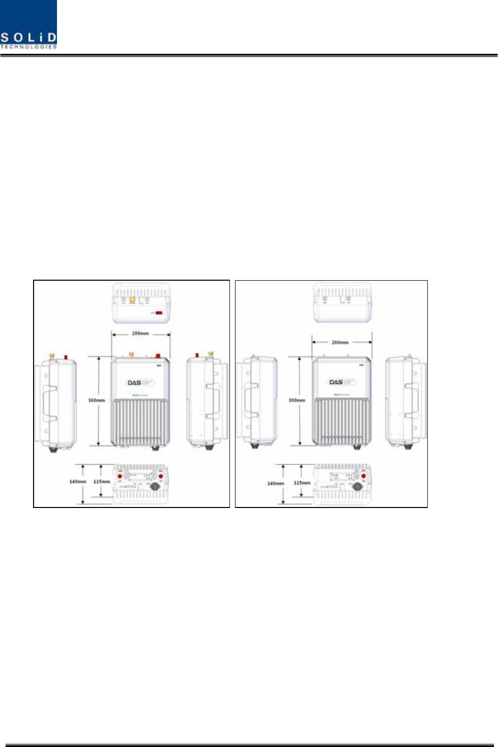
Figure5.13–WallmountdimensionsfortheROU ............................................. 98
Figure5.14–ROUinstallationproceduresidebyside ........................................ 99
Figure5.15–ROUinstallationdiagramsidebyside.......................................... 100
Figure5.16–ROUinstallationprocedureforstackedmounting ....................... 101
Figure5.17–ROUinstallationdiagramforstackedmounting........................... 101
Figure5.18–ROUinstallationprocedureforverticalrack ................................ 102
Figure5.19–ROUinstallationdiagramforverticalrack ................................... 103
Figure5.20–ROUinstallationprocedureforhorizontalrack ........................... 104
Figure5.21–ROUinstallationdiagramforhorizontalrack ............................... 104
Figure5.22–ROUPowerPortview ................................................................ 106
Figure5.23–ROUopticalPortview ................................................................ 108
Figure5.24–ROUGNDPortview ................................................................... 109

Confidential&Proprietary9/122 SC‐DAS
Figure5.25–ROULEDindicatorinformation................................................... 110
Figure5.26–OEUPowerinterfacediagram .................................................... 114
Figure5.27–OpticalcablewithSC/ACPTypeConnectors.............................. 116
Figure5.28–OEUwithDOUsinserted ............................................................ 116
Figure6.1–SC‐DASLinkbudgetfortheBIU .................................................... 120
Figure6.2–MDBUinformationassignedattheBIU.......................................... 123
Figure6.3–MDBUmenuinformationattheBIU ............................................. 124
Figure6.4–MDBUnameassignmentattheBIU............................................... 127
Figure6.5–MDBUnameassignmentatthetree ............................................. 127
Figure6.6–MDBUModuleFailureinformationattheBIU ............................... 128
Figure6.7–ConfigurationofBIU‐ODU‐ROUforbasictopology........................ 130
Figure6.8–ConfigurationofBIU‐ODU‐ROUforexpansiontopology................ 131
Figure6.9–DOUassignmentattheBIU.......................................................... 133
Figure6.10–ODUMenuinformation............................................................... 134
Figure6.11–SC‐DASLinkbudgetforROU........................................................ 135
Figure6.12–OpticalinformationattheROU ................................................... 138
Figure6.13–ROUinformationassignment ...................................................... 140
Figure6.14–ROUMenuinformation............................................................... 141
Figure6.15–ROUSoftkeyinformation ............................................................ 143
Figure6.16–SC‐DASLinkBudgetforOEU ....................................................... 144
Figure6.17–OEUOpticalinformation ............................................................. 147
Figure7.1–Shutdownlogicdiagram................................................................ 151
Figure7.2–Opticallossinformation................................................................ 154

Confidential&Proprietary10/122 SC‐DAS
Section1
Safety&CertificationNotice

Confidential&Proprietary11/122 SC‐DAS
“Onlyqualifiedpersonnelareallowedtohandlethisunit.Readandobeyallthewarning
labelsattachedinthisusermanual”
Anypersonnelinvolvedininstallation,operationorserviceoftheSOLiDTechnologyrepeaters
mustunderstandandobeythefollowing:
‐ Obeyallgeneralandregionalinstallationandsafetyregulationsrelatingtoworkonhighvoltage
installations,aswellasregulationscoveringcorrectuseoftoolsandpersonalprotective
equipment.
‐ Thepowersupplyunitinrepeaterscontainsdangerousvoltagelevelswhichcancauseelectric
shock.Switchthemainsoffpriortoanyworkinsucharepeater.Anylocalregulationsaretobe
followedwhenservicingrepeaters.
‐ Therepeatercover(door)shouldbesecurelyfastenedinopenposition(withacord),during
outdoorworkinordertopreventdoorfromslammingduetowind(whichcouldcausebodily
harmordamage).
‐Usethisunitonlyforthepurposespecifiedbythemanufacturer.Donotcarryoutanymodifications
orreplaceanypartswhicharenotsoldorrecommendedbythemanufacturer.Thiscouldcause
fire,electricshockorotherinjuries.
‐ Repeatersgenerateradiosignalsandtherebygiverisetoelectromagneticfieldsthatmaybe
hazardoustoanypersonintheimmediateproximityoftherepeaterandtherepeaterantennas
foranextendedperiodoftime.
‐Duetopowerdissipation,thisrepeatermayreachaveryhightemperature.Donotoperatethisunit
onorclosetoflammablematerials.
‐Donotuseanysolvents,chemicals,orcleaningsolutionscontainingalcohol,ammonia,orabrasives.
‐Certification
z FCC:ThisequipmentcomplieswiththeapplicablesectionsofTitle47CFRParts15,22,24and
90
z UL/CUL:ThisequipmentcomplieswithULandCUL1950‐1Standardforsafetyforinformation
technologyequipment,includingelectricalbusinessequipment
z FDA/CDRH:ThisequipmentusesaClass1LASERaccordingtoFDA/CDRHRules.Thisproduct
conformstoallapplicablestandardsof21CFRChapter1,SubchaperJ,Part1040
‐ForPLUGGABLEEQUIPMENT,thesocket‐outletshallbeinstalledneartheequipmentandshallbe
easilyaccessible.

Confidential&Proprietary12/122 SC‐DAS
Section2
SystemOverview
2.1Generaloverview
2.2Systemoverview

Confidential&Proprietary13/122 SC‐DAS
2.1 Generaloverview
SC‐DASplatformisacoveragesystemforin‐buildingservicesdeliveringseamless,highqualityvoice
anddataAsadistributedantennasystem,itprovidesanaloganddigitalphoneservicesinmultiple
bandsthroughoneantenna.
Thesystemcoverspublicandprivatevenuessuchas:
z Shoppingmalls
z Hotels
z Campusareas
z Airports
z Clinics
z Subways
z Multi‐usestadiums,conventioncenters,etc.
Thesystemenhancesin‐buildingradioenvironmentsthatlacksignalqualitybyimprovingtheRSSI
andEc/Io.Byprovidingcommunicationservicesthroughoutthebuilding,thesystemenablesusersto
makeacallsanywhereinthecoveragearea.
Thesystemusesbothanalog(AMPS)anddigital(TDMA,CDMAandWCDMA)methods.
TheSC‐DASsystemsupportscommunicationstandardsandpublicinterfaceprotocolsinworldwide
use.
z Frequencies:VHF,UHF,700MHz,800MHz,850MHz900MHz,1900MHz,2100MHz,etc.
z Voiceprotocols:AMPS,TDMA,CDMA,GSM,IDEN,etc.
z Dataprotocols:EDGE,GPRS,WCDMA,CDMA2000,Paging,LTE,etc.
SC‐DAScomprisesfrequencyspecificmodules.Coverageforaspecificfrequencybandis
accomplishedbyinsertingacorrespondingfrequencymoduleintoeachunit.Becauseitdelivers
multiplesignalswithonestrandofsinglemodefiber,thesystem,requiresnoadditionalhardware
modificationswheneveranewfrequencyisadded.
Thesystemisfeaturedwiththefollowing:
z Flexibiltiy&Scalabiltiy
Supportsfiber‐opticportsupto32or60(usingOEU)
Connectsmultiple‐buildings(campus)asoneDAS
z Modularstructures
Modularfrequencyupgrade
Plug‐intypemodules
z Multi‐Band,Singleoperator
SupportsmultipleservicesfromoneWSP

Confidential&Proprietary14/122 SC‐DAS
Supportmulti‐operatorinaband(Max.2operator)
z LowOPEX/CAPEX
Compactdesign
Upgradabledesign
Easyinstallationandmaintenance
AdoptsautoIDscheme
TheSC‐DASplatformwillservetwoprimarysegments;firstasacarrierdeployedcoverage
enhancementproductfortheirspecificfrequenciesandsecondasalowcost,publicsafety/single
carrierproduct.
Confidential&Proprietary15/122 SC‐DAS
2.2 Systemoverview
SC‐DAScomprisesthecomponentslistedbelow.
ThebasesystemconsistsofaBIU(BTSInterfcaceUnit),anODU(OpticdistributionUnit)andaROU
(RemoteOpticUnit).ForusewithmultipleROU’s,ithasOEU(OpticExpansionUnit).
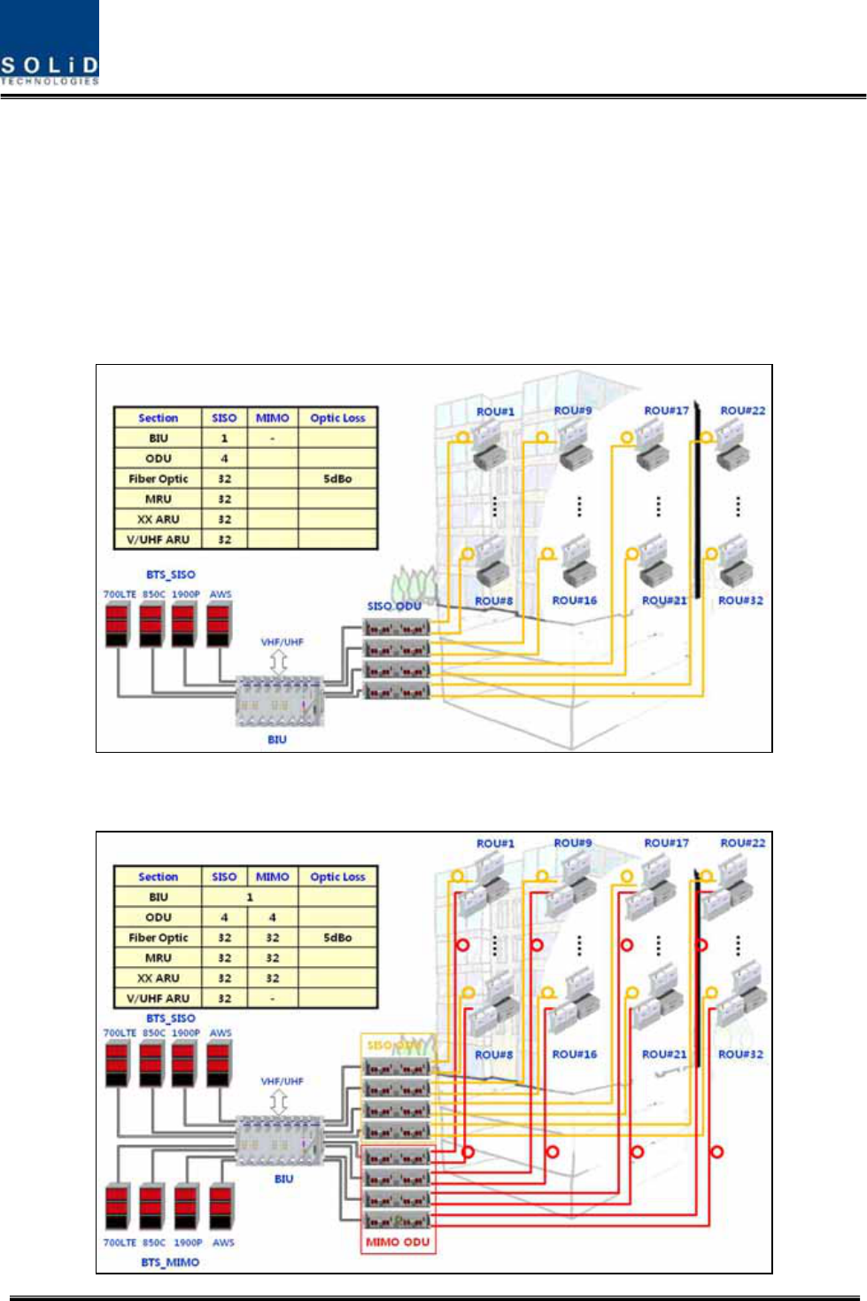
TheBIUhastwolayerwhichsupportbothSISOandMIMOconfigurationusingseparateopticalfiber
cable.Fig2.1showsbasicsystemtopologyforSISO
Figure2.1–BasicsystemtopologysupportingSISOconfiguration

Confidential&Proprietary16/122 SC‐DAS
Figure2.2–BasicsystemtopologysupportingMIMOconfiguration
AsshownatFig.’s2.1and2.2,onestrandoffiberisneededforSISOconfigurationbuttwostrands
areneededforMIMOcofigurationwhenconnectedwithanROU.Applicationsrequiringupto
32ROU’sforSISOarepossiblewithoneBIU.EachSISOROUwillrequireanadditionalstrandof
fiberandanadditional32ROU’scanbeaddedtothesamesystemforMIMOapplications.MIMO
requires2strandsoffiberperROUaswellasMIMOspecificODU’s.
Confidential&Proprietary17/122 SC‐DAS
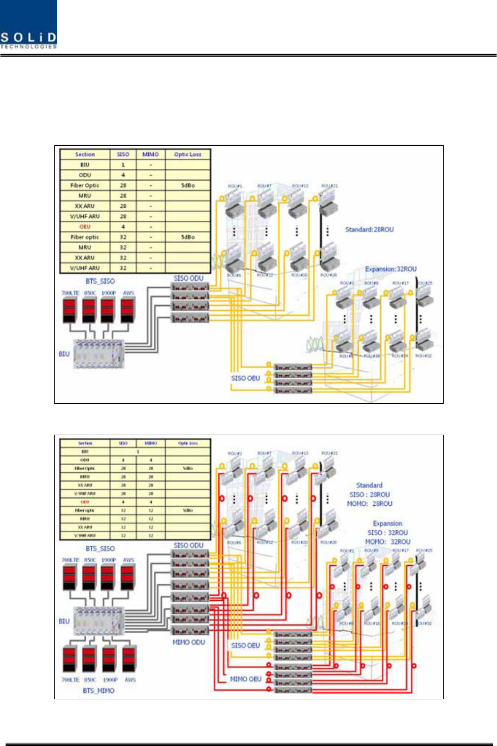
Toreducenumberofopticalcablesbetweenmulti‐buildingapplications,wecanutilizethe
OEU(OpticalExpansionUnit)
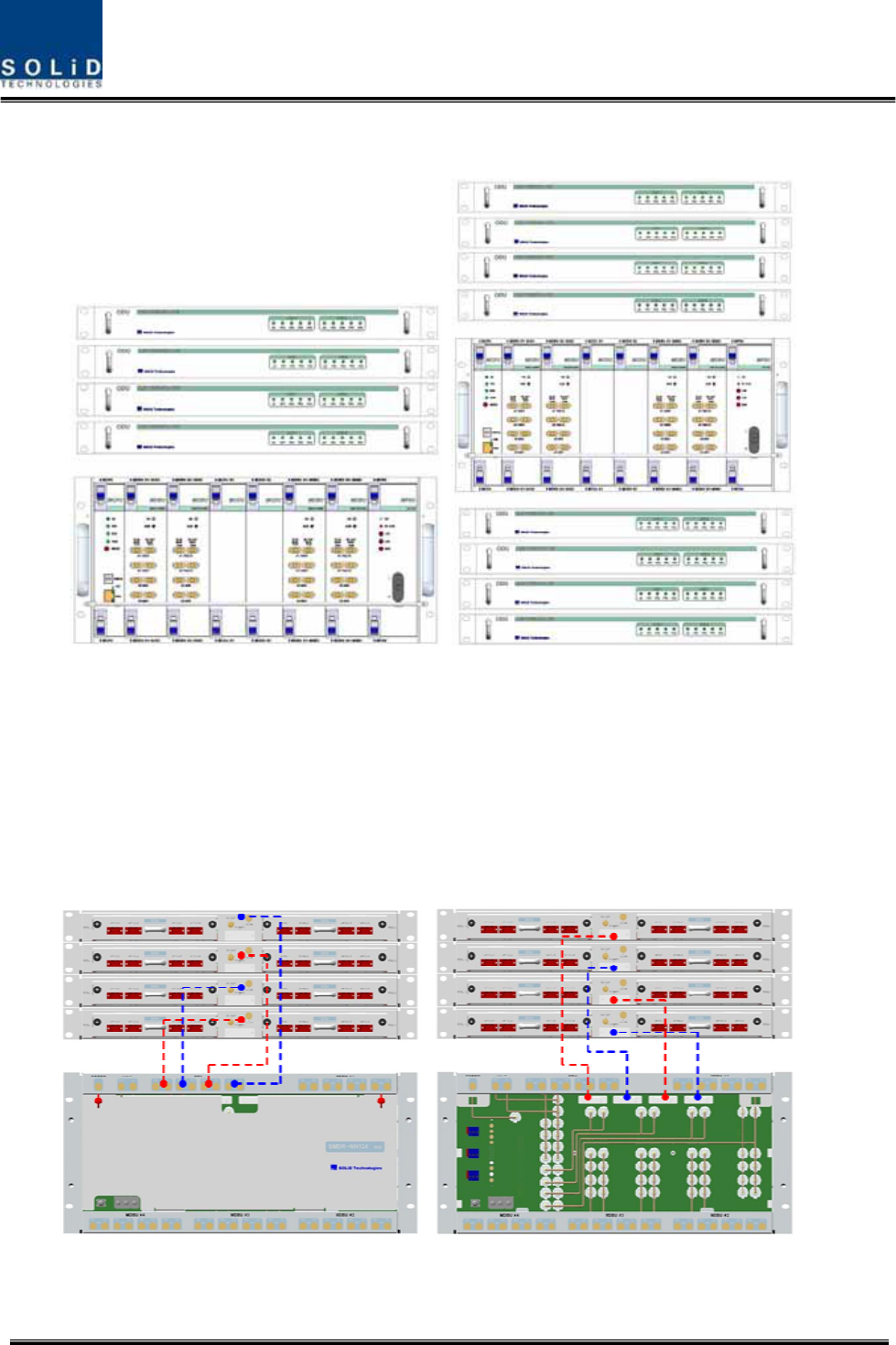
Fig2.3showsexpansionsystemtopologysupportingSISOconfigurationusingOEUs
Figure2.3–ExpansionsystemtopologysupportingSISOconfiguration
Figure2.4–ExpansionsystemtopologysupportingMIMOconfiguration

Confidential&Proprietary18/122 SC‐DAS
Fig2.4showsexpansionsystemtopologysupportingMIMOconfigurationusingOEU
Section3
SystemSpecifications
3.1Systemspecifications
3.1.1PhysicalSpecifications
3.1.2OpticwavelengthandLaserpower
3.1.3Environmentalspecifications
3.1.4Availablefrequencybands
3.1.5BandSpecifications

Confidential&Proprietary19/122 SC‐DAS
3.1 Systemspecifications
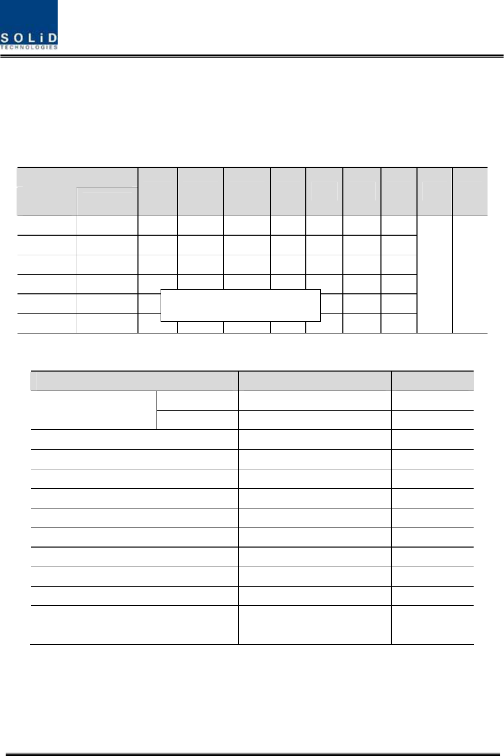
3.1.1 PhysicalSpecifications
ParameterBIUODUOEUMRUARU
RFConnectors4SMApairs(TX,RX)
perMDBU2SMA‐
1N‐type
2SMA:optical
2SMA:RF
2SMA:optical
2SMA:RF
ExternalAlarm
connector
(Drycontacts)
TB:4pcsforoutput
TB:3pcsforinput
‐ ‐ ‐ ‐
SerialInterface
connector1USB(B)type 1USB(B)type1USB(B)type1USB(B)type
Fiberconnector‐ 8pcs,SC/APCfor
ROU
1SC/APCforODU
8SC/APCforROU1SC/APCforODU‐
LEDAlarmand
StatusIndicator
MDBUStatus
z Powerstatus
z ALMstatus
MCPU
z Powerstatus
z TXComm
z RXComm
z ALMstatus
MPSU
z Powerstatus
z DCALMstatus
DOU1Status
z LDstatus
z PD1/2/3/4
status
DOU2Status
z LDstatus
z PD1/2/3/4
status
EWDMStatus
z LDstatus
z PDstatus
DOU1Status
z LDstatus
z PD1/2/3/4
status
DOU2Status
z LDstatus
z PD1/2/3/4
status
Systemstatus
z Powerstatus
z TX1Comm
z RX1Comm
z TX2Comm
z RX2Comm
z ALMstatus
Systemstatus
z Powerstatus
z TXComm
z RXComm
z ALMstatus
z Optstatus
Systemstatus
z Powerstatus
z TXComm
z RXComm
z ALMstatus
ACPower‐ ‐
NormalRange:120VAC
50/60Hz
Operatingrange
108~132VAC,50/60Hz
Sametoleftside
DCPower
Normalrange:‐48
VDC
Operatingrange:
‐40.8~‐57.6VDC
BeprovidedbyBIU
Normal:‐48VDC
Operatingrange:
‐40.8~‐57.6VDC
Sametoleftside
Power
consumption
SISOMode:162W
(IncludingSISOODU
4EA)
MIMOMode:315W
(IncludingSISOODU
4EA+MIMOODU
4EA)
28W
(Including
DOU2EA)
40W
(IncludingDOU2EA)
MRU1900P+850C:50W
MRU1900P:45W
ARU700LTE+AWS:40W
ARU900I+800I:44W
Enclosure
Dimensions
482.6(19”)x
221.5(5U)x450
482.6(19”)x
43.6(1U)x450
482.6(19”)
x88.1(2U)x450300x200x258300x200x258
Weight[FullLoad]26.2Kg6Kg9.6Kg6.6Kg6.8Kg

Confidential&Proprietary20/122 SC‐DAS
3.1.2 OpticalwavelengthandLaserpower
ParameterODUOEUROU
OpticalWavelength
TX:1310nm
RX:1550nm
Westoptic
TX:1550nm,RX:1310nm
Eastoptic
TX:1310nm,RX:1550nm
TX:1550nm
RX:1310nm
Outputpower1.5dBm±1dBmtoROU,OEU
1dBm±1dBmtoROU
7dBm±1dBmtoODU
7dBm±1dBmtoODU
Returnloss<45dB<45dB<45dB
3.1.3 Environmentalspecifications
ParameterBIU,ODU,OEUROU/AOR
OperatingTemperature‐10to+50°C‐10to+50°C
OperatingHumidity,noncondensing‐ 5%to90%
3.1.4 AvailableFrequencyBands
Frequencyrange
Standard UnitnamingDescription
TX(MHz)RX(MHz)
Status
iDEN700PSPublicsafety763to775793to805Infuture
iDEN800PSPublicsafety851to869806to824Completed
Cellular850CCellular869to894824to849Completed
iDEN900ISMR935to940896to901Completed
Paging900PAPaging929to930896to902Infuture
PCS1900PPCS1930to19951850to1915Completed
AWS‐1AWS‐1AWS‐12110to21551710to1755Completed
VHFVHFPublicsafety136to174136to174Infuture
UHFPublicsafety(Band1)
396to450
450to512
396to450
450to512
Infuture
E‐UHF
UHF
Publicsafety(Band2)
380to434
434to496
380to434
434to496
Infuture
LTE700LTELongTermEvolution728to756
698to716
777to787
Completed
Confidential&Proprietary21/122 SC‐DAS
3.1.5 BandSpecifications
SC‐DASplatformallowsmanybandcombinationsaswellasdifferentoutputpowerlevels
withinthebanddependingonthecombination.
1)Outputpowerlevel
BelowtableshowsOutputpowerlevelasafunctionofbandcombination
BandCombinations
MRUARU
700PS
700LTE
800PS/I
850C
900I
1900P
AWSVHFUHF
1900P+850C700LTE+AWS
‐ 24dBm‐24dBm
‐ 28dBm
28dBm
1900P+AWS‐ ‐ ‐ ‐‐‐30dBm
30dBm
1900P900I+800I‐ ‐ 26dBm‐26dBm
31dBm
‐
1900P‐‐‐‐‐‐30dBm
‐
1900P+850C700PS+800PS
21dBm‐ 21dBm21dBm
‐ 30dBm
‐
700PS+800PS900I+800I21dBm‐ 21dBm21dBm
‐ ‐
24dBm24dBm
2)GeneralSpecifications
ParameterSpecificationsRemark
TX25dB/step1dBROU
GainControlrange
RX20dB/step1dBBIU
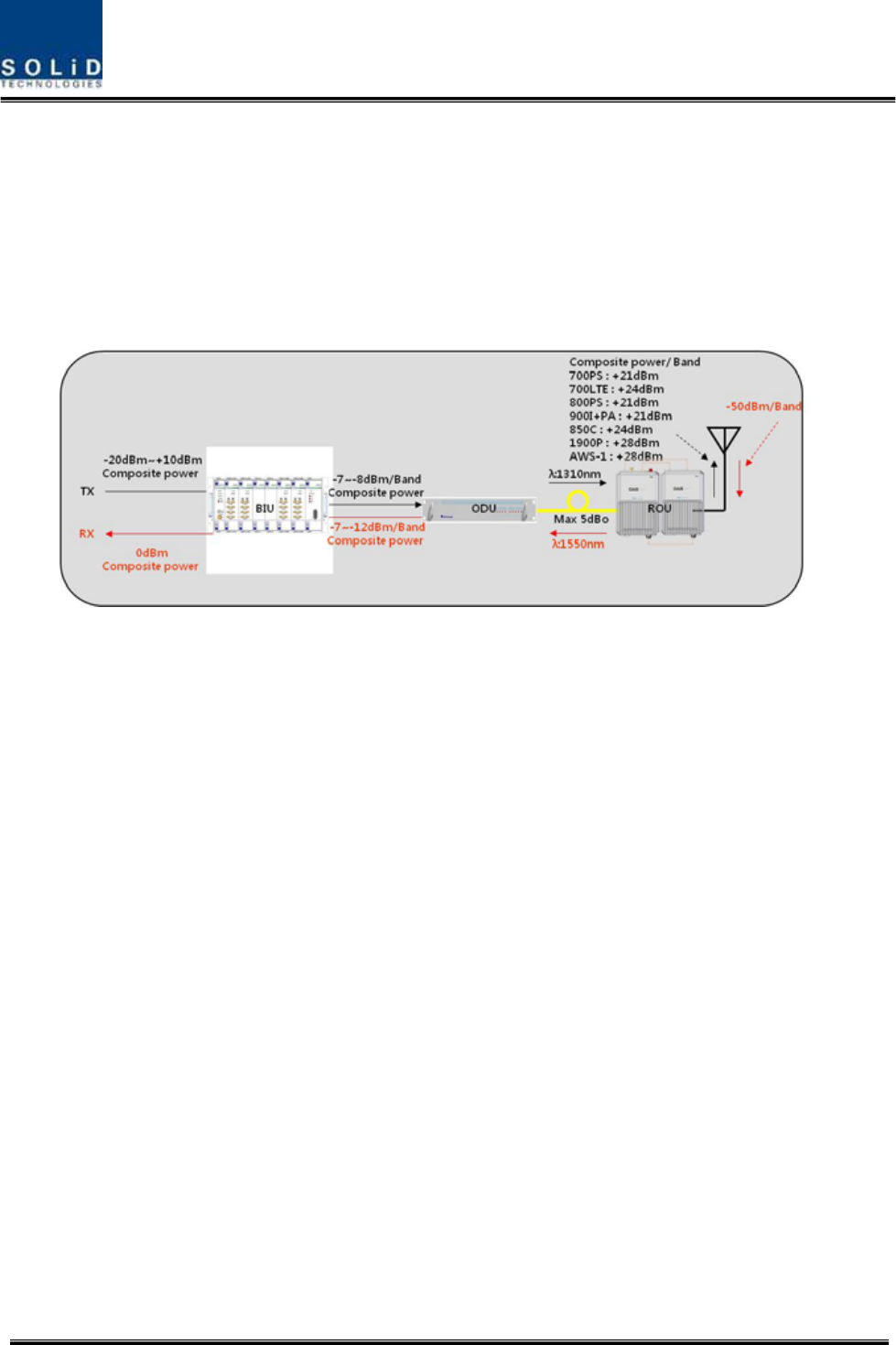
TXinputpower‐20dBm~+10dBm
SpuriousEmission<‐13dBm
OpticalLinkAGC>10dB
VSWR1.8:1
Pass‐bandRipple4dBp‐p
MaxopticalLoss5dBo
Opticalwavelength1310nm/1550nmwithWDM
RXoutputpower0dBm
RXinputpower‐50dBmMax
NoiseFigure<8dB
Excluding700PS,
800PS
On the loadmap

Confidential&Proprietary22/122 SC‐DAS
Section4
SystemConfigurationandFunctions
4.1BIU(BTSInterfaceUnit)
4.2ODU(OpticdistributionUnit)
4.3OEU(OpticExpansionUnit
4.4ROU(RemoteOpticUnit)
Confidential&Proprietary23/122 SC‐DAS
4.1 BIU(BTSInterfaceUnit)
TheBIUreceivessignalsfromtheBTSorBDAthroughcoaxialcableandtransmitstofour
ODUs(OpticDistributionUnit).andTheBIUseparatesRXsignalsreceivedfromODUs
accordingtotheirfrequencyband.
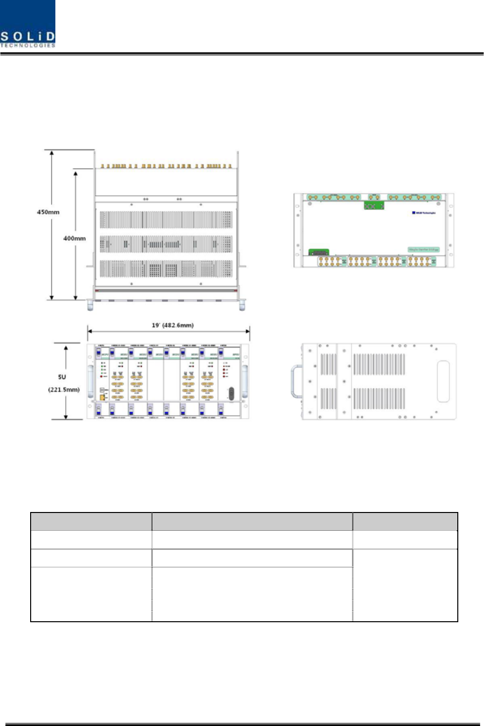
Figure4.1–BIUfrontandsideviews
4.1.1 BIUSpecifications
ItemSpec.Remark
Size482.6(19”)x221.5(5U)x450mm
Weight26Kg
Powerconsumption
SISOMode:168W(IncludingSISOODU4EA)
MIMOMode:315W(IncludingSISOODU
4EA+MIMOODU4EA)
FullLoad
Confidential&Proprietary24/122 SC‐DAS
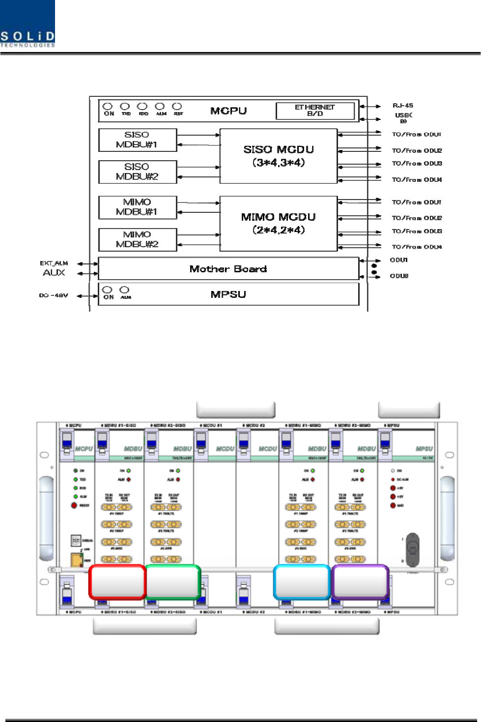
4.1.2 BIUblockdiagram
Figure4.2–BIUblockdiagram
4.1.3 BIUassemblies
MDBU
#2
MDBU
#1 MDBU
#3 MDBU
#4
SISO Side MIMO Side
MCDU’s MPSU
Figure4.3–BIUmountingdiagram

Confidential&Proprietary25/122 SC‐DAS
No.UnitDescriptionRemark
1MDBU
MainDriveBTSUnit
Amplify&adjustdownlinkRFsignal
Amplify&adjustuplinkRFsignal
Max4EA
2MCDU
MainCom/DivUnit
Combine3EAdownlinksignalanddivide4EAsignaltoODU
Combine4EAuplinksignalanddivide3EAsignaltoMDBU
SupportVHF/UHFinterfaceport
3MCPU
MainCentralProcessorUnit
Controlandmonitoringsystemstatus
ControlandmonitoringwithUSB(B)
Allowsaccesstoupper‐levelnetworkthroughGSMorEthernet
4MPSUMainPowerSupplyUnit
Inputpower:DC‐48V,Outputpower:9V,6V
5M/B
MotherBoard
Providesignalinterfaceandpowerforeachunit
Providefourportsfordrycontactoutput
Providethreeportsforinput
ProvidetwoAuxportsforfutureusage
6Shelf19inch,5U
4.1.4 SubAssemblyDescription
1)MainDriveBTSUnit(MDBU)
MDBUdeliversTXsignalsfromtheBTSorBDAtorelateddevicesaswellasdeliversRXsignalsfrom
thesedevicestotheBTSorBDA.ThisunitalsomonitorsTXinputlevel.UsingtheinputAGCfunction,
itautomaticallyadjustsinputATTaccordingtoinputpower.ItalsohasanATTtoadjustRXgain.The
MDBUvariesperfrequencybandtoincludingthefollowing:
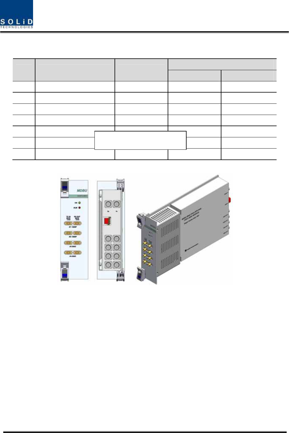
Confidential&Proprietary26/122 SC‐DAS
In/outRFPort
NoUnitnamingDescription
TXRX
11900P+850CDualBand4Port4Port
2700LTE+AWS‐1DualBand4Port4Port
31900PSingleBand2Port2Port
4900I+800IDualBand4Port4Port
51900P+AWS‐1DualBand4Port4Port
6700PS+800PSDualBand4Port4Port
7900IDualBand2Port2Port
Figure4.4–MDBUataglance
2)MainCom/DivUnit(MCDU)
MCDUcombinesTXsignalsthataredeliveredfromMDBUperfrequencybandanddeliversthemto
fourODUs.ItalsocombinesRXsignalsfromuptofourODUsandsendsthemtouptofour
MDBUs.TheunithasaporttointerfacewithVHF&UHFsignals.IthasanATTforinputmonitoringand
inputcontrol.
TheunithasareservedportforfutureusagesuchasLMUinterface,additiveMDBUinterface,etc,
On the loadmap
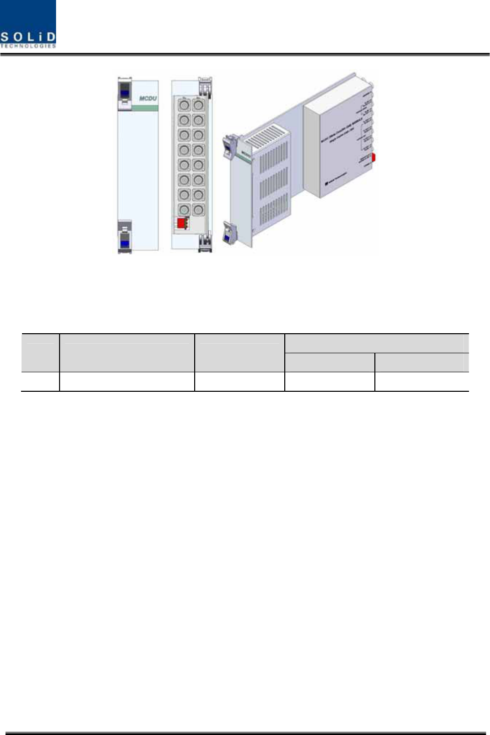
Confidential&Proprietary27/122 SC‐DAS
Figure4.5–MCDUataglance
VHF+UHFfrequencybandincludesthefollowing:foruseinfuture
In/outRFPort
NoUnitnamingDescription
TXRX
1VHF+UHFDualBand1Port1Port
3)MainCentralProcessorUnit(MCPU)
MCPUcaninquireandcontrolthestateofthemodulesthatareinstalledintheBIU.
ThisunitcaninquireandcontrolthestateofuptofourODUs.Throughcommunication,italsocan
inquireandcontrolROUsthatareconnected.
Inaddition,theunithasUSB(B)portforlocalmonitoringsothatitcaninquireandcontrolstateof
devicesthroughaPC.Onthefrontpanel,ithascommunicationLEDindicatorstocheck
communicationstatewithROU.ItalsohasALMLEDindicatorstoshowwhetheradeviceisfaulty.
Foraccesstouppernetwork,ithasaporttoinsertanEthernetportandGSMmodeminit.
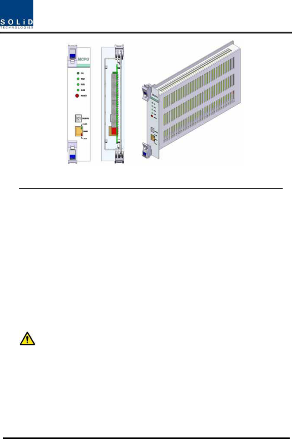
Confidential&Proprietary28/122 SC‐DAS
Figure4.6–MCPUataglance
IntheMainCentralProcessorUnit,alithiumbatteryisinstalledforRTC(RealTimeControl)function.
CAUTION
RISKOFEXPLOSIONMAYOCCURIFBATTERYISREPLACEDBYANINCORRECTTYPE
DIPOSEOFUSEDBATTERIESACCORDINGTOTHEINSTRUCTIONS
[INSTRUCTION]
Theequipmentandaccessoriesincludinginnerlithiumbatteryaretobedisposedofsafelyafterthe
lifespanofthemaccordingtothenationalregulation.Donotattempttoreplacethelithiumbattery
unlessauthorizedbyaqualifiedservicepersonnel,toavoidanyriskofexplosion.
Confidential&Proprietary29/122 SC‐DAS
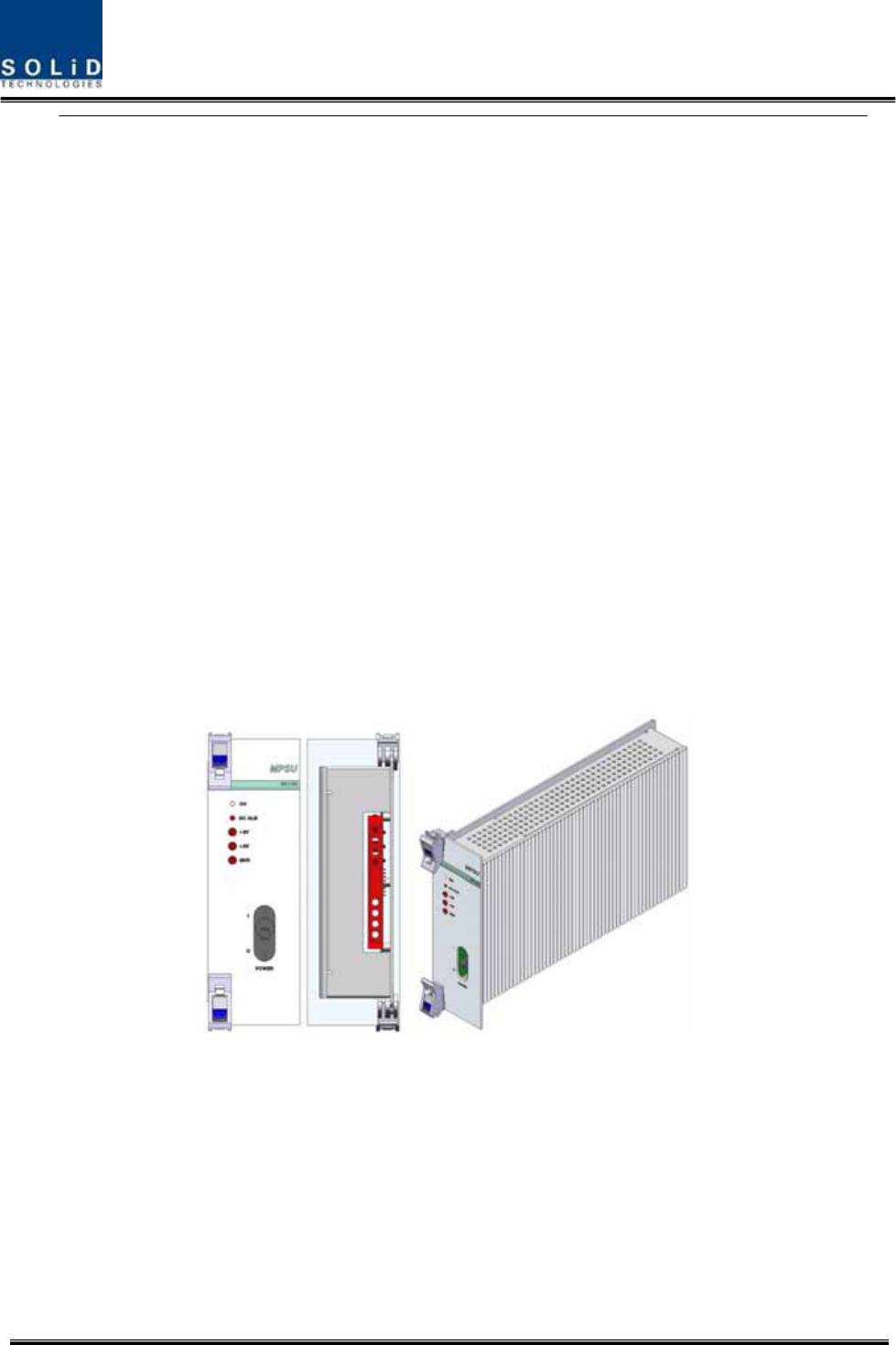
4)MainPowerSupplyUnit(MPSU)
TheMPSUtakesa‐48Vinputandoutputs+6Vand+9VDCpower.
Onthefrontpanel,thisunithasanoutputtestportanditalsohasDCALMLEDIndicatortoshow
faultyoutput.
Figure4.7–MPSUataglance
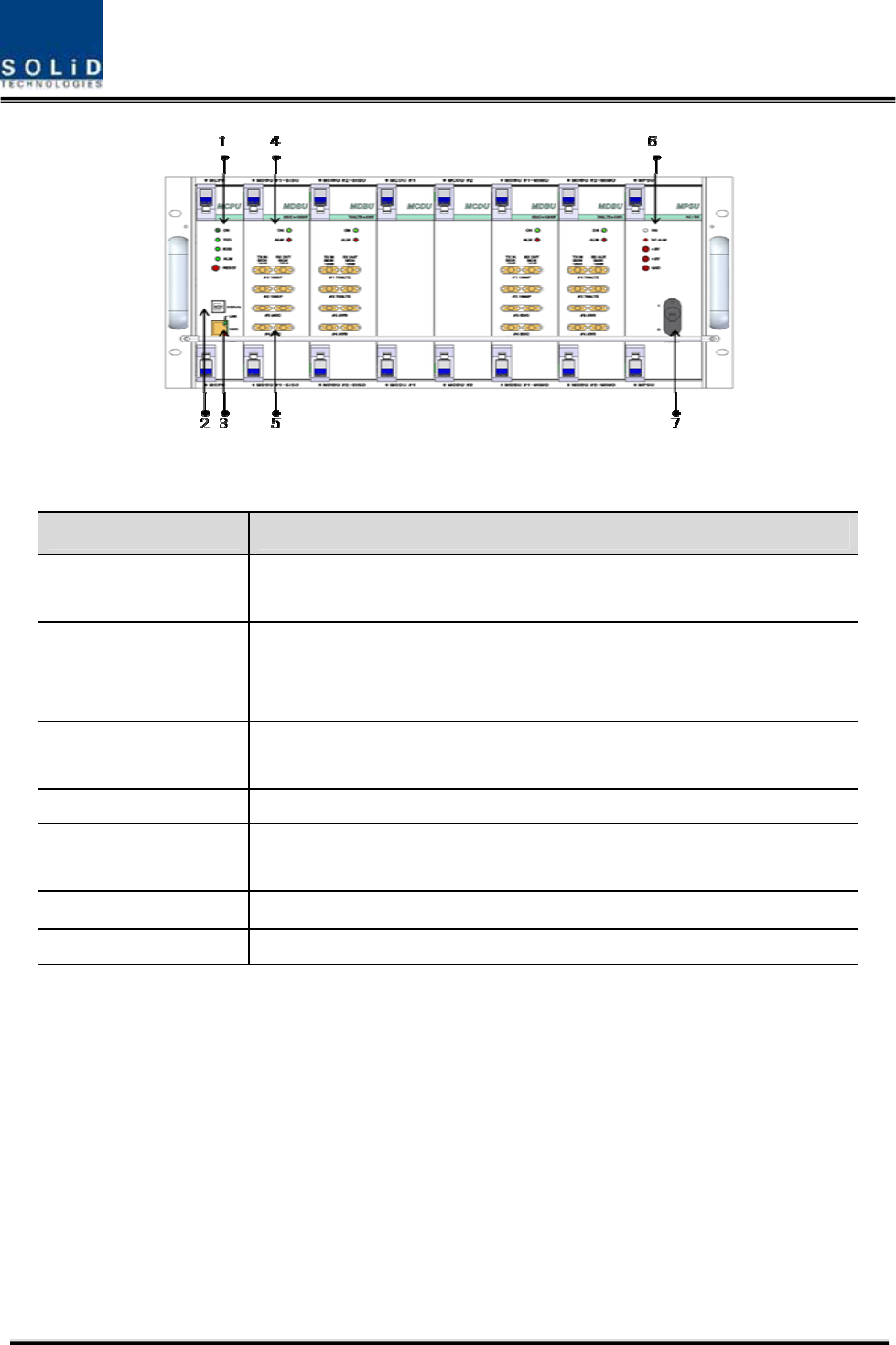
4.1.5 BIUfront/rearpaneloverview
1)Frontpanel
Confidential&Proprietary30/122 SC‐DAS
Figure4.8–BIUfrontpanelview
ItemDescription
1.AlarmLED&ResetCommunicationstatewithdevices,alarmstatusofthesystemandreset
switch
2.DEBUG(USBB)
USBportforcommunicationanddiagnosisofdevicesthroughPC/laptop
Thisequipmentisforindooruseonlyandallthecommunicationwiringsare
limitedtoindooruseaswell.
3.NMS(Ethernetport)Ethernetportforuppernetwork
ThesupportingnetworkmodeisUDPprotocol
4.MDBULEDLEDtoshowwhetherMDBUisinstalledandisoperatingproperly
5.RFMonitorPort20dBCouplingcomparedwithTXInputLevel
20dBCouplingcomparedwithRXOutputLevel
6.PwrTestPort&ALMOutputDCpowertestportandALMLEDtoshowabnormalstate,ifany
7.PowerswitchPowerON/OFFswitch
Confidential&Proprietary31/122 SC‐DAS
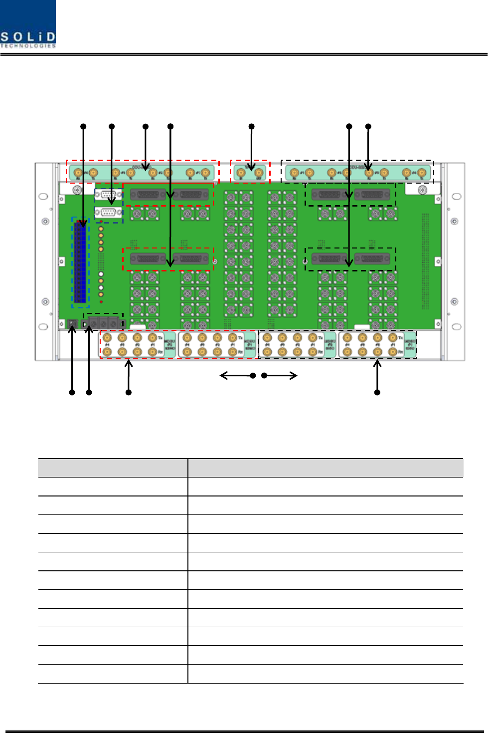
2)Rearpanel
Figure4.9–Rearpanelview
ItemDescription
1.DCInputPortInputterminalforDC‐48V
2.ExternalALMPortInput/outputterminalfordrycontact
3.GNDPortSystemgroundterminal
4.AUXI/OPortReservedPortforfutureuses
5.MIMOODUI/OPortRFsignalinterfaceterminalforODU
6.MIMOODUsignalPortPowerandsignalinterfaceterminalforODU
7.MIMOBTS/BDAI/OPortInput/outputinterfaceterminalofBTS/BDA
8.V/UHFI/OPortRFsignalinterfaceterminalofVHF&UHF
9.SISOODUI/OPortRFsignalinterfaceterminalforODU
10.SISOODUsignalPortPowerandsignalinterfaceterminalforODU
11.SISOBTS/BDAI/OPortInput/outputinterfaceterminalofBTS/BDA
1
5
8 9 6 10
SISO SIDE MIMO SIDE
3 4
7 11 2
Confidential&Proprietary32/122 SC‐DAS
4.2 ODU(OpticdistributionUnit)
ODUreceivesTXRFsignalsfromupperBIUandconvertsthemintoopticalsignals.Theoptical
signalsaresenttoROUthroughopticalcables.ThisunitconvertsopticalsignalsfromROUintoRF
signalsandsendstheconvertedsignalstoBIU.
ForeachshelfoftheODU,uptotwoDOUs(DonorOpticUnit)canbeinstalledinit.
OneDOUissupportedwithfouropticalports.Therefore,oneODUcanbeconnectedwitheight
ROUs.
UptofourODUscanbeconnectedwithBIUeachSISOandMIMOpath
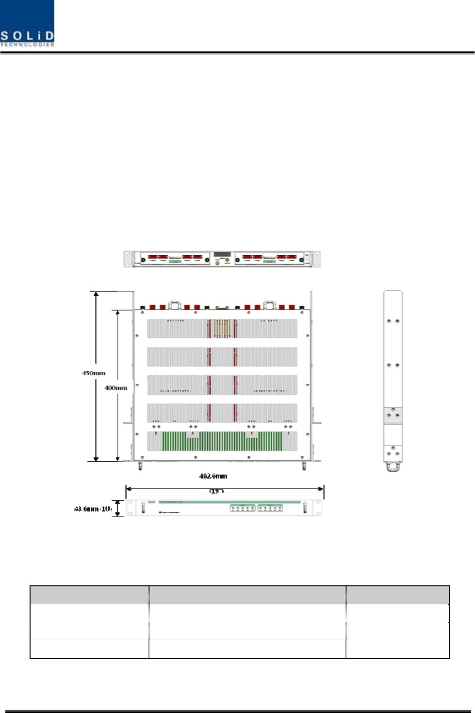
Figure4.10–ODUataglance
4.2.1 ODUspecifications
ItemSpec.Remark
Size482.6(19”)x43.6(1U)x450mm
Weight6kg
Powerconsumption27W
FullLoad
Confidential&Proprietary33/122 SC‐DAS
4.2.2 ODUblockdiagram
Figure4.11–ODUblockdiagram
4.2.3 ODUassemblies
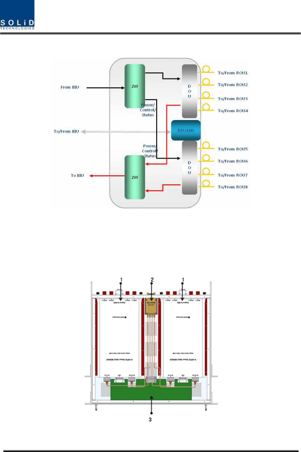
Figure4.12–ODUInternalView

Confidential&Proprietary34/122 SC‐DAS
No.UnitDescriptionRemark
1DOU
DonorOpticUnit
ConvertsTXRFsignalsintoopticalsignals;
ConvertsRXopticalsignalsintoRFsignals;
ProvidesuptofouropticalportsperDOU
Max2ea.
22W
2WayDivider
DividesTXRFsignalsintotwo;
CombinestwoRXRFsignalsintoone
3DUDistributionUnit
DistributespowerandsignalstoDOU
4Shelf19”rack,1RU
5Accessories25PINDSUB,Maletofemale1pcs
RFCoaxialCableAssembly2pcs
4.2.4 SubAssemblydescription
1)DonorOpticUnit(DOU)
TheDOUperformstheRFtoopticalconversionofTXsignalsaswellastheopticaltoRFconversion
ofRXsignals.
Usinganopticalsplitter,thisunitdividesopticalsignalsfromaLaserDiodeintofourandthen
distributesthemtoeachopticalport.WithatotaloffourPhotoDiodesinRX,theDOUperformsthe
opticaltoRFconversionofsignalsreceivedfromeachopticalport.Inaddition,theunitisequipped
withanATTtocompensateforopticallossinthefiberorfiberconnectors.
SinceisusesaWDM,itusesonlyonestrandoffiberforeachROUitconnectsto.
WithinternalFSKmodem,itwillallowoperationfromaremotesite.
Confidential&Proprietary35/122 SC‐DAS
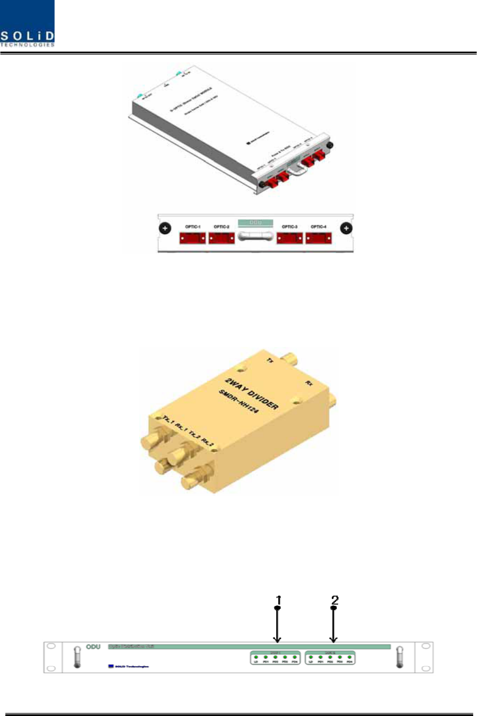
Figure4.13–DOUataglance
2)2WayDivider(2W)
The2waydividerisequippedwithtwo2‐waysplittersinasinglehousingandthesplittersworkfor
TX/RXsignals,respectively.
Designedinbroadbandtype,thedividercombinesandsplitssignalsfrom/totheBIU
Figure4.14–2WayDividerataglance
4.2.5 ODUfront/rearpaneloverview
1)Frontpanel
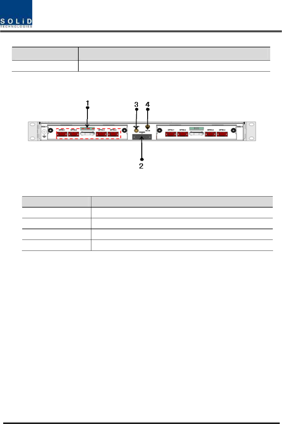
Figure4.15–ODUfrontpanelview
Confidential&Proprietary36/122 SC‐DAS
ItemDescription
1,2LEDindicatortocheckforfaultyDOUmodule.
2)Rearpanel
Figure4.16–ODURearpanelview
ItemDescription
1.OpticPortSC/APCopticalconnectorterminal;useoneopticalcableperROU.
2.DCI/OPortTerminalforpowerandstatevalues
3.RXRFPortRXRFsignalinterfaceterminal
4.TXRFPortTXRFsignalinterfaceterminal
Confidential&Proprietary37/122 SC‐DAS
4.2.6 ODUInterfacewithBIU
SISOConfigurationMIMOConfiguration
Figure4.17BIU/ODUinterface
ForSISOconfiguration,uptofourODUscanbestacked.abovethetopoftheBIU.
ForMIMOconfiguaration,uptoeightODUscanbestackedabove/belowtheBIU.
Inthiscase,itisrecommendedtoleavea1RUspacebetweenBIUandtheODUsotherwiseheatfrom
BIUmaydegradetheperformanceoftheODUs,
Figure4.18–BIU/ODUInterfacerearview
Confidential&Proprietary38/122 SC‐DAS
Asshowninthefigurebelow,connectonecoaxialcableforTXandanothercoaxialcableforRXwith
correspondingportsattherearofBIU.Forpowersupplyandcommunication,connect25PinD‐Sub
Connectorcabletothecorrespondingport.
Figure4.19–BIU/ODUinterfacedetails
Confidential&Proprietary39/122 SC‐DAS
4.3 OEU(OpticExpansionUnit)
OEUismainlyusedtoremotelydeliversignalsforCampusclusters.Attheupperpart,thisunit
combineswithODUandreceivesTXopticalsignalstoconvertthemintoRFsignals.Then,it
regeneratesthesignalstosecureSNRandconvertsthemintoopticalsignals.Thesignalsaresentto
ROUthroughopticalcables.WhenitreceivesRXopticalsignalsfromROU,theunitconvertsthem
intoRFsignalstoregeneratethesignalsandthenconvertsthemintoopticalsignalstosendthemto
ODU.
InOEU,oneshelfcanbeequippedwithuptotwoDOUs.TheDOUisthesameasthemoduleused
forODU.UptofourOEUscanbeconnectedwithODU.
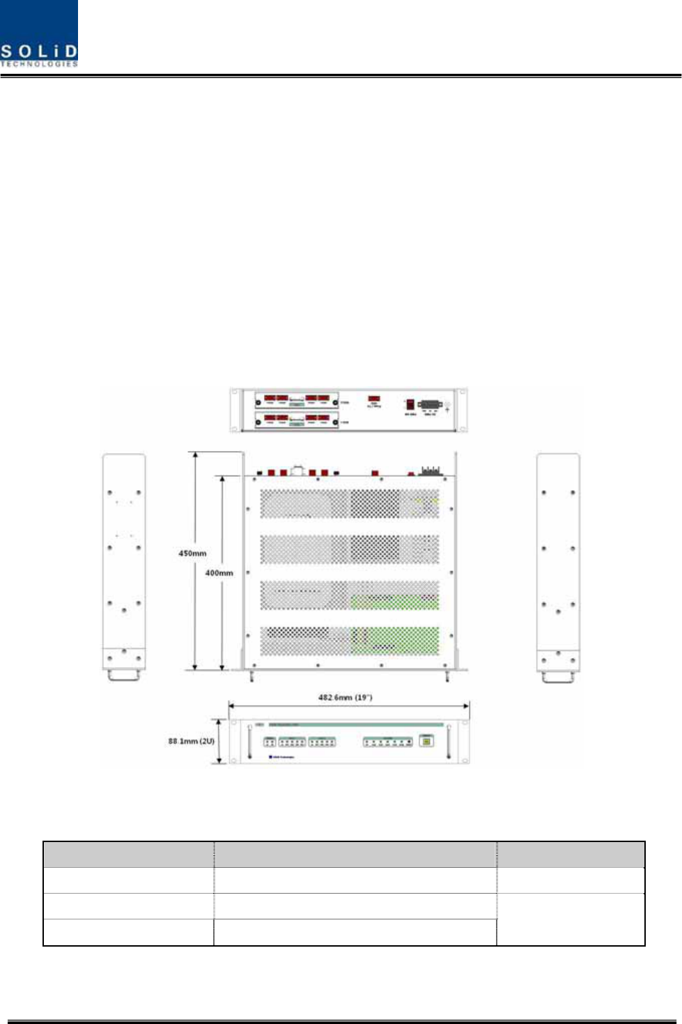
Figure4.20–OEUataglance
4.3.1 SpecificationsofOEU
ItemSpec.Remark
Size482.6(19”)x88.1(2RU)x450mm
Weight9.5kg
Powerconsumption40W
FullLoad
Confidential&Proprietary40/122 SC‐DAS
4.3.2 OEUblockdiagram
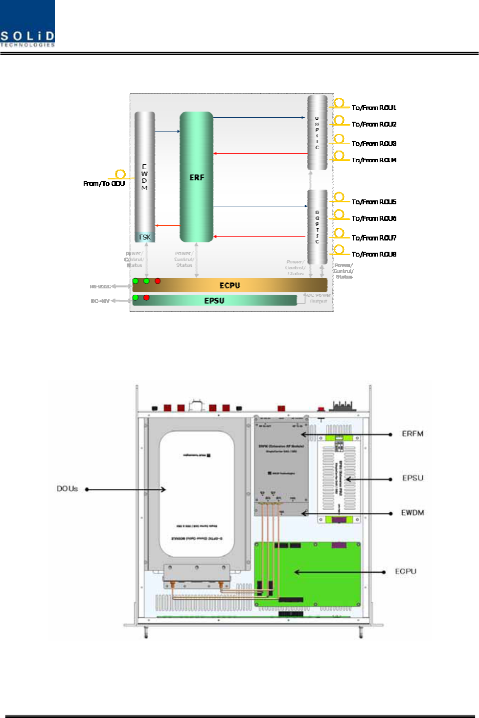
Figure4.21–OEUblockdiagram
4.3.3 OEUassemblies
Figure4.22–OEUinternalview
Confidential&Proprietary41/122 SC‐DAS
No.UnitDescriptionRemark
1DOU
DonorOpticUnit
ConvertTXRFsignalsintoopticalsignals;
ConvertRXopticalsignalsintoRFsignals;
ProvideuptofouropticalportsperDOU
Max2ea.
2EWDM
ExpansionWavelengthDivisionMultiplexer
ConvertTXopticalsignalsintoRFsignals;
ConvertRXRFsignalsintoopticalsignals;
CompensatesforopticalcablelosswithODU
3ECPU
ExpansionCentralProcessorUnit
Controlandmonitoringsystemstatus
ControlandmonitoringwithRS232
RelaysstatevaluesofROUtoBIU
4EPSUExpansionPowerSupplyUnit
Inputpower:DC‐48V,Outputpower:9V,6V
5ERFM
ExpansionRadioFrequencyModule
RegenerateTXsignalsandtransmitFSKmodemsignals;
RegenerateRXsignalsandreceiveFSKmodemsignals
6Shelf19”rack,2RU
4.3.4 SubAssemblydescription
1)DonorOpticUnit(DOU)
TheDOUisthesameasthemoduleusedfortheODU.
Figure4.23–DOUataglance
Confidential&Proprietary42/122 SC‐DAS
2)ExpansionWavelengthDivisionMultiplexer(EWDM)
EWDMmodulehandlestheopticaltoRFconversionofTXsignalsaswellastheRFtooptical
conversionofRXsignals.ThismultiplexercommunicateswiththeBIUusingthebuiltinFSKmodem.
ItalsohasanATTtocompensateforopticalcablelossbetweenODUs.
Finally,ithasinternalWDMsoitneedsonlyoneopticalcabletoworkwithanROU.
Figure4.24–EWDMataglance
3)ExpansionCentralProcessorUnit(ECPU)
ECPUcanqueryandcontrolthestateofmodulesinstalledintotheOEU.Thisunitsimultaneoulsy
communicateswiththeBIUandtheROUaswellasactingascommunicationbridgebetweenBIUand
ROU.
Inaddition,theunithasaUSBportforlocalcommunicationwhichenablesqueryandcontrolof
devicesthorughaPC.Atthefrontpanel,communicationLEDindicatorindicatescommunication
withupperBIUandlowerROU.ItalsohasanALMLEDindicatortoshowfault.
Figure4.25–ECPUataglance
4)ExpansionRadioFrequencyModule(ERFM)
ERFMrepairsSignaltoNoisedegradedbyopticalmodules.
Confidential&Proprietary43/122 SC‐DAS
Figure4.26–ERFMataglance
5)ExpansionPowerSupplyUnit(EPSU)
AsDC/DCConverter,theEPSUreceives‐48VDCinputandprovides+9Vand+6VofDCpower
requiredforOEU.
Figure4.27–EPSUataglance
Confidential&Proprietary44/122 SC‐DAS
4.3.5 OEUfront/rearpaneloverview
1) Frontpanel
Figure4.28–OEUfrontpanelview
ItemDescription
1.EWDMLEDLEDindicatortocheckEWDMstatetoseeifitisabnormal
2.DOULEDLEDindicatortocheckDOUmodulestatetoseeifitisabnormal
3.SystemLEDandResetCommunicationstatewithdevices,alarmstatusofthesystemandreset
switch
4.NMS(USBPort)
USBportforcommunicationanddiagnosisofdevicesthroughPC/laptop.
Thisequipmentisforindooruseonlyandallthecommunicationwiringsare
limitedtoindooruseaswell.
2)Rearpanel
Figure4.29–Rearpanelview
ItemDescription
1.GNDPortTerminalforsystemground
2.DCInputPortInputterminalforDC‐48V
3.powerswitchPowerON/OFFswitch
4.To/FromODUOpticPortSC/APCopticalconnectorterminal
5.To/FromROUOpticPortSC/APCopticalconnectorterminal;useoneopticalcableperROU.
Confidential&Proprietary45/122 SC‐DAS
4.4 ROU(RemoteOpticUnit)
TheROUconsistsoftwounits:theMRU(MainRemoteUnit)andtheARU(AddonRemoteUnit).The
ROUisconsideredthecombinationofMRUandARU.
TheMRUreceivesTXopticalsignalsfromtheODUortheOEUandconvertsthemintoRFsignals.
TheconvertedRFsignalsareamplifiedthroughaHighPowerAmpinacorrespondingRU,combined
withtheMultiplexerandtransmittedouttheantennaport.
TheROUreceivesRXsignalsthroughtheantennaport,filtersout‐of‐bandsignalsinacorresponding
RUandsendstheresultstoRemoteOpticModuletomakeRFtoopticalconversionofthem.After
converted,thesignalsaresenttoaupperdevice(theODUorOEU).
TheMRUandARUhaveamaximumof2bands.
ThemaindifferencebetweenanMRUanARUisthepresenceofanopticalmodule.
(a)MRU(b)ARU
Figure4.30–ROUataglance

Confidential&Proprietary46/122 SC‐DAS
4.4.1 ROUspecifications
ItemBandcombinationSize
(WxHxD)WeightPower
consumption
Remark
MRU1900P+850C6.6kg50W
Band
Combination1
ARU700LTE+AWS‐16.8kg40W
MRU1900P6.5kg45W
Band
Combination2
ARU900I+800I6.7kg44W
Tobedeveloped
Band
Combination3
Tobedeveloped
200x300x140
mm
Full
load
Confidential&Proprietary47/122 SC‐DAS
4.4.2 ROUblockdiagram
4.4.2.1 CombinationofMRU1900PCS+850C/ARU700LTE+AWS‐1
RCU
Cavity Filter
USB
(B type)
AC 120V
Or
DC -48V
Power/
Control/
Status
MRFM
ANT(N-Female)
EX_PORT
EX_PORT
RXD
Reset
ON TXD
ALM Opt
LOW
HIGH
From/To ODU
LD
FSK TX
SC/APC
V/UHF RX
ARU TX
WDM
PD ARU RX
V/UHF TX
Power/
Control/
Status
EX_PORT
LOW
HIGH
MRU TX
MRU RX
USB
(B type)
FSK RX
RCU
Cavity Filter
ARFM
MRU 1900PCS+850C ARU 700LTE+AWS-1
RXD
Reset
ON TXD
ALM Opt
AC/
DC
Or
DC/
DC
AC/
DC
Or
DC/
DC
AC 120V
Or
DC -48V
Figure4.31–ROUblockdiagramforMRU1900PCS+850CandARU700LTE+AWS‐1
4.4.2.2 CombinationofMRU1900PCS/ARU900I+800I
RCU
1900P
Cavity Filter
USB
(B type)
Power/
Control/
Status
MRFM
ANT(N-Female)
EX_PORT
EX_PORT
RXD
Reset
ON TXD
ALM Opt
LOW
From/To ODU
LD
FSK TX
SC/APC
V/UHF TX
ARU TX
WDM
AC/
DC
Or
DC/
DC
PD
ARU RX
V/UHF RX
Power/
Control/
Status
EX_PORT
LOW
MRU TX
MRU RX
USB
(B type)
FSK RX
RCU
800I/900I
Cavity Filter
ARFM
1900P MRU 800I+900I ARU
AC/
DC
Or
DC/
DC
RXD
Reset
ON TXD
ALM Opt
OPT SIU
AC 120V
Or
DC -48V
AC 120V
Or
DC -48V
Figure4.32–ROUblockdiagramforMRU1900PCSandARU900I+800I
Confidential&Proprietary48/122 SC‐DAS
4.4.3 ROUassemblies
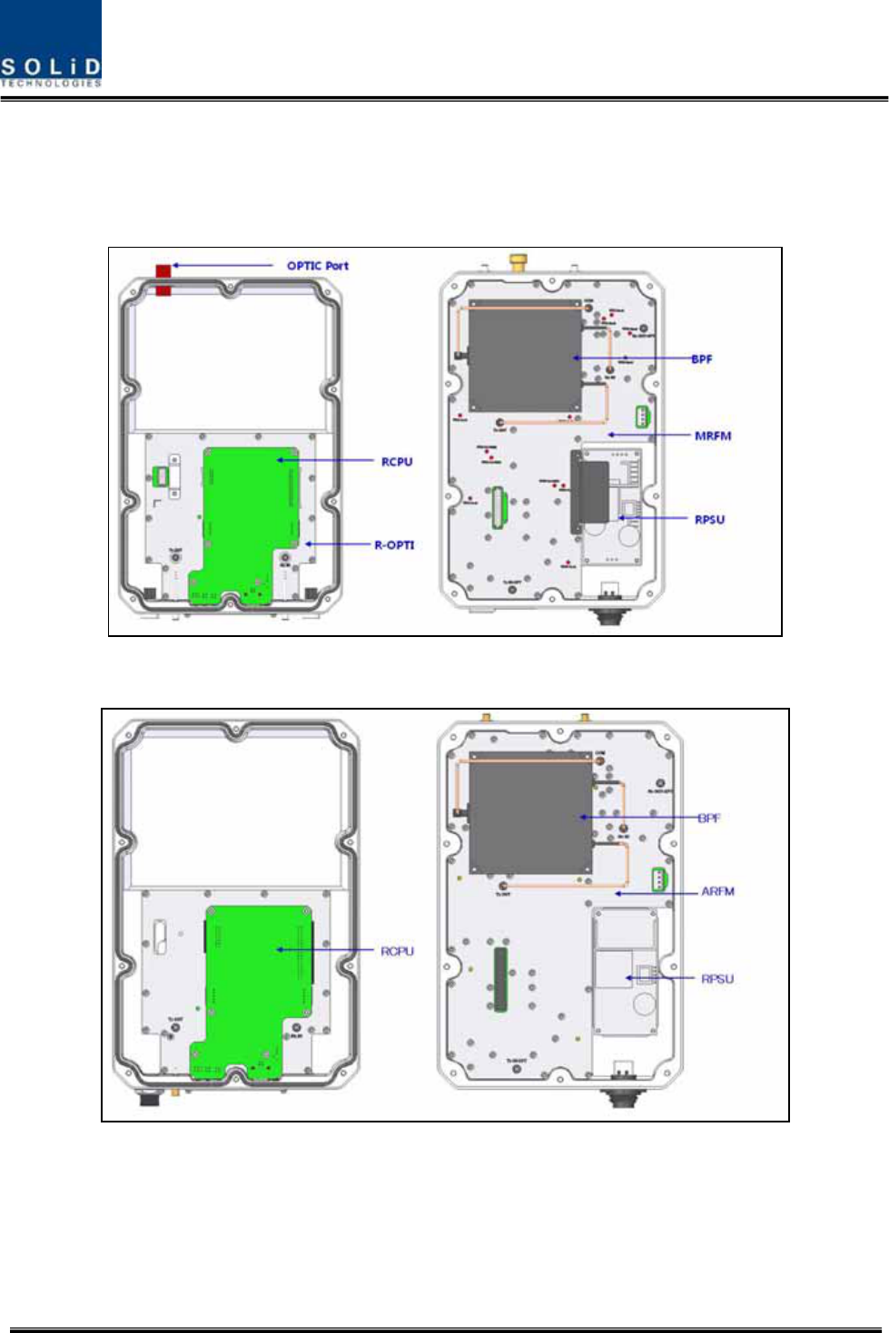
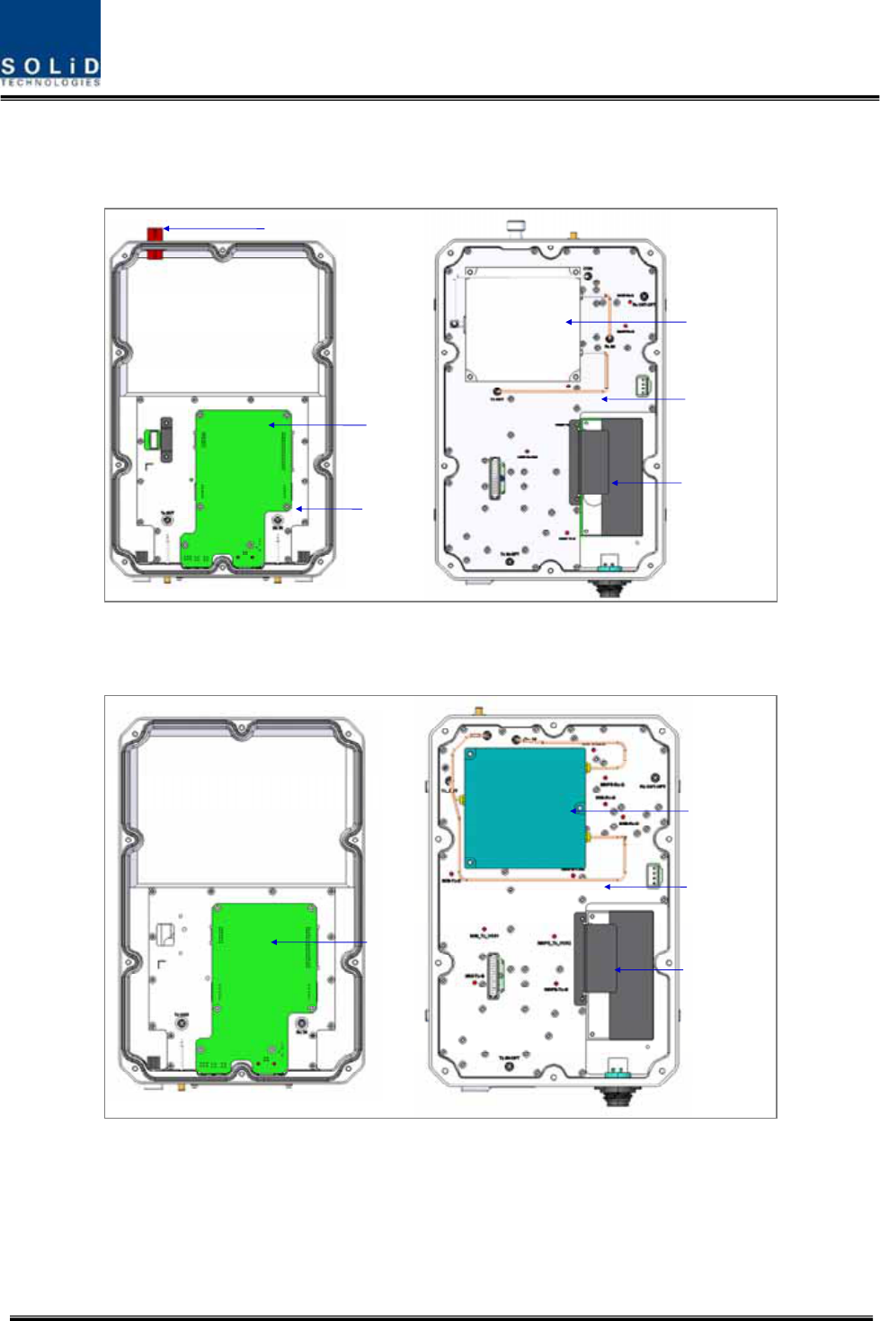
4.4.3.1 CombinationofMRU1900PCS+850C/ARU700LTE+AWS‐1
(a)MRU1900PCS+850C
(b)ARU700LTE+AWS‐1
Figure4.33–ROUinternalviewforMRU1900PCS+850CandARU700LTE+AWS‐1
Confidential&Proprietary49/122 SC‐DAS
4.4.3.2 CombinationofMRU1900PCS/ARU900I+800I
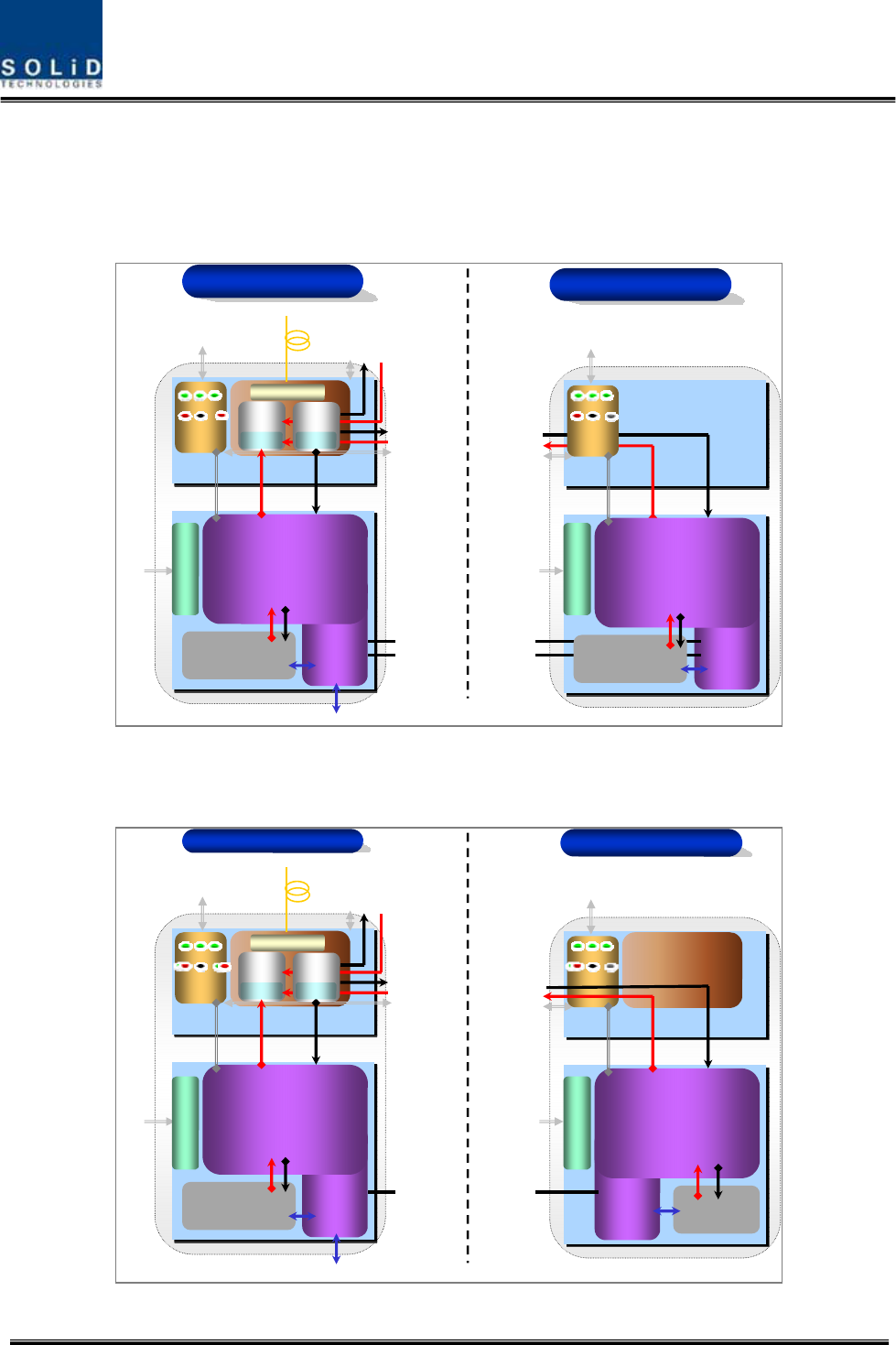
BPF
MRFM
RPSU
RCPU
R-OPTIC
OPTIC Port
(a)MRU1900PCS
BPF
ARFM
RPSU
RCPU
(b)ARU900I+800I
Figure4.34–ROUinternalviewforMRU1900PCSandARU900I+800I

Confidential&Proprietary50/122 SC‐DAS
No.UnitDescriptionRemark
1MRFM/ARFM
+BPF
Main/AddonRFModule
FilterandheavyamplificationofTXsignals;
FilterandamplifyRXsignals;
RemoveothersignalsthroughBPF
2RPSU
RemotePowerSupplyUnit
Inputpower:DC‐48VorAC120V,Outputpower:25V
For120VinputofAC/DC;
For‐48VinputofDC/DC
3R‐OPT
RemoteOptic
MakeRFconversionofTXopticalsignals;
ConvertRXRFsignalsintoopticalsignals;
Compensatesopticallossinterval
CommunicateswithBIUorOEUthoughtheFSKmodem
4RCPU
RemoteCentralProcessorUnit
Controlssignalofeachunit
MonitorsBIU/ODU/OEUstatusthroughFSKmodem
communication
5Enclosure
EnableWallMount;
Checkifthesystemisnormal,throughthebottompanel
LED
Confidential&Proprietary51/122 SC‐DAS
4.4.4 SubAssemblydescription
1)MainRFModule/AddonRFModule(MRFM/ARFM)+BPF
WhenreceivingTXsignalsfromeachbandthroughR‐Opt,MRFM/AFRMfiltersthesignalsand
amplifiesthemwiththeHighPowerAmpifier.TheunitalsofiltersRXsignalsreceivedthroughthe
antennaportandamplifiesthemaslownoisetosendthesignalstoR‐Opt.
Intheunit,thereisanATTtoadjustgain.Thisdevicevariesforeachfrequencyband,includingthe
following:
BPF
NoCombinationUnitnamingDescription
CavityFilterCeramicFilter
MRU1900P+850CMRFM1900P+850C Dual.1900PCS850C
1
ARU700LTE+AWS‐1ARFM700LTE+AWS‐1Dual.700LTEAWS‐1
MRU1900PMRFM1900PSingle1900PCS‐
2
ARU900I+800IARFM900I+800IDual900IEN/800IDEN‐
3Tobedeveloped‐ ‐ ‐ ‐
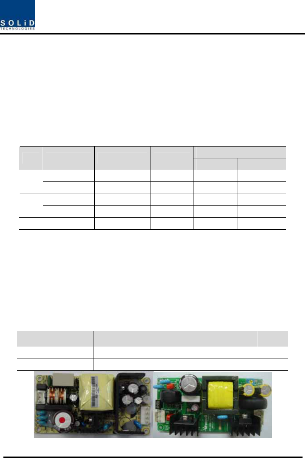
2)RemotePowerSupplyUnit(RPSU)
RPSUaccepts‐48VDCinput.Thisunitisconfigured2ways:theDC/DCtypeoutputs+25VofDCpower
andAC/DCtypetakes120VACinputandoutputs+25VofDCpower.
Pleasespecifywhichtypewhenordering.MSConnector,whichusesportstoreceiveinputs,is
designedforeitherACandDCinputconfiguration.Theinputcableisdifferentdependingoninput
voltageconditions.
TheRPSUdoesn’thaveaswitchtoturnthepowerON/OFF.Unitisactivewhenpowerisconnected.
Here,youshouldcheckforrangeofinputpowerasfollows:
No.UnitRangeofinputpowerRemark
1AC/DC90to264VAC
2DC/DC‐42Vto‐56VDC
(a)AC/DC(b)DC/DC

Confidential&Proprietary52/122 SC‐DAS
Figure4.35–PSUataglance
3)RemoteOptic(R‐OPT)
TheRemoteOpticperformstheopticaltoRFsignalconversionaswellastheRFtooptical
conversion.WithanFSKmodeminit,theunitcommunicateswiththeotherdevices.
ItalsohasaninternalATTtocompensateforopticalcableloss.TheopticalwavelengthforTXpathis
1310nmand1550nmfortheRXpath.ItistransportedbyafiberstrandusingWDM(Wavelength
DivisionMultiplexing)technique
4)RemoteCentralProcessorUnit(RCPU)
TheRCPUcanmonitorandcontroltheRU.Thisunitreceivesandanalyzesuppercommunication
datafromRemoteOpticandreportstheunit'sownvaluetotheupperdevices.Atthebottomofthe
module,ithasanLEDindicatortoshowsystemstatus,lettingyoucheckanyfaultconditions.The
samepanelalsohascommunicationLEDIndicatorstoshowcommunicationstatuswithupper
devices.ThroughtheUSBPort,theunitenablesyoutocheckandcontroldevicestatusthroughaPC
orlaptop.Thisequipmentisforindooruseonlyandallthecommunicationwiringsarelimitedto
indooruseaswell.TheRCPUoftheMRUhavetwoportstoconnectexteranldevices(theARUand
theVHF&UHFARU).Usinganexternalinterfacecable,theMRUcancommunicatewiththe
ARU/VHF&UHFARU.
TheMRUcollectsstatusinformationfromARU/VHF&UHFARUandthencommunicateswiththe
upperdevice
Confidential&Proprietary53/122 SC‐DAS
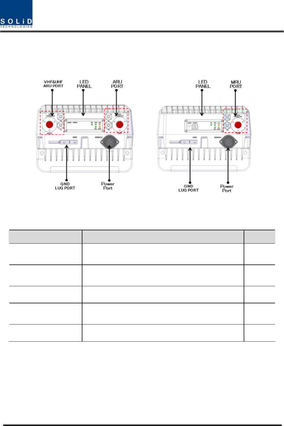
4.4.5 BottomofROU
1)Functions
(a)MRU(b)ARU
Figure4.36–ROUBottomview
ItemDescriptionRemark
1.VHF/UHFARUPortTerminalforTXandRXRFportsofVHFandUHF
TerminalforsignalporttointerfacewithVHFandUHF
2.LEDPANELVisibleLEDindicatorpanelforcheckingfaultstatusUSBPortto
checkandcontroldevicestatusthroughPCandlaptop
3.PowerPortAC120VinputportorDC‐48Vinputport
4.ARU/MRUPortTerminalforTXandRXRFportsofMRU/ARU
TerminalforsignalporttointerfacewithMRU/ARU
5.GNDLUGPORTTerminalforsystemground
PowerPort
Adifferenttypeofpowerportisusedsupplying‐48VDCor120VAC,andspecificpower
cableshouldbeappliedtoeachdifferenttypeofROUpowersupply(AC/DCorDC/DC).
Belowfigureshowsdifferentpowerconnectors.

Confidential&Proprietary54/122 SC‐DAS
(a)AC/DC(b)DC/DC
Figure4.37–ROUPowerPortView
Confidential&Proprietary55/122 SC‐DAS
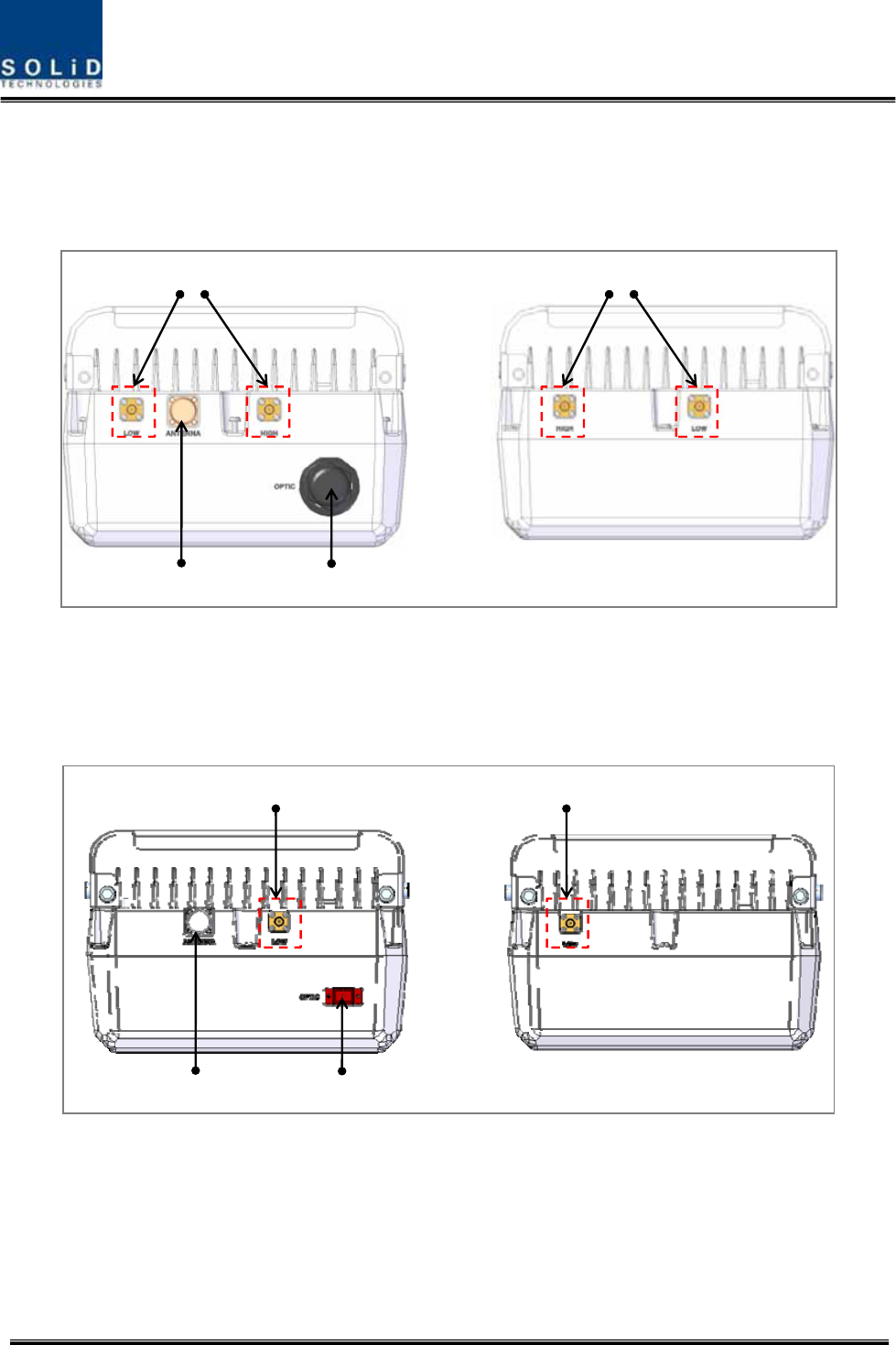
4.4.6 TopofROU
4.4.6.1 CombinationofMRU1900PCS+850C/ARU700LTE+AWS‐1
RFPORT
OpticPort
ANT
Port
RFPORT
(a)MRU(b)ARU
Figure4.38–ROUTopViewforMRU1900P+850CandARU700LTE+AWS‐1
4.4.6.2 CombinationofMRU1900PCS+850C/ARU700LTE+AWS‐1
RFPORT
OpticPort
ANT
Port
RFPORT
(a)MRU(b)ARU
Figure4.39–ROUTopViewforMRU1900P+850CandARU700LTE+AWS‐1

Confidential&Proprietary56/122 SC‐DAS
ItemDescriptionRemark
1.RFPortTerminalforLowRFporttoconnectbetweenMRUandARURF
TerminalforHIGHRFporttoconnectbetweenMRUandARURF
2.ANTPortTerminalforRFporttoconnecttoantenna
3.OpticPortTermnialforOpticalporttoconnectwithfibercable
ThefiberconnectortypeisSC/APC

Confidential&Proprietary57/122 SC‐DAS
Section5
SystemInstallation&Operation
5.1BIUInstallation
5.2ODUInstallation
5.3ROUInstallation
5.4OEUInstallation
Confidential&Proprietary58/122 SC‐DAS
Thischapterdescribeshowtoinstalleachunitandcorrespondingfibercables,alongwithpower
cablingmethod.
Indetail,thechapterdescribeshowtoinstallshelvesorenclosuresofeachunit,PowerCabling
method,OpticCablingandRFInterface.Furthermore,byshowingpowerconsumptionofmodules
installedineachunit,athePowerCablingbudgetiseasilydetermined.Last,itdescribesthequantity
ofcomponentsofmodulestobeinstalledineachunitalongwithanexpansionmethod.
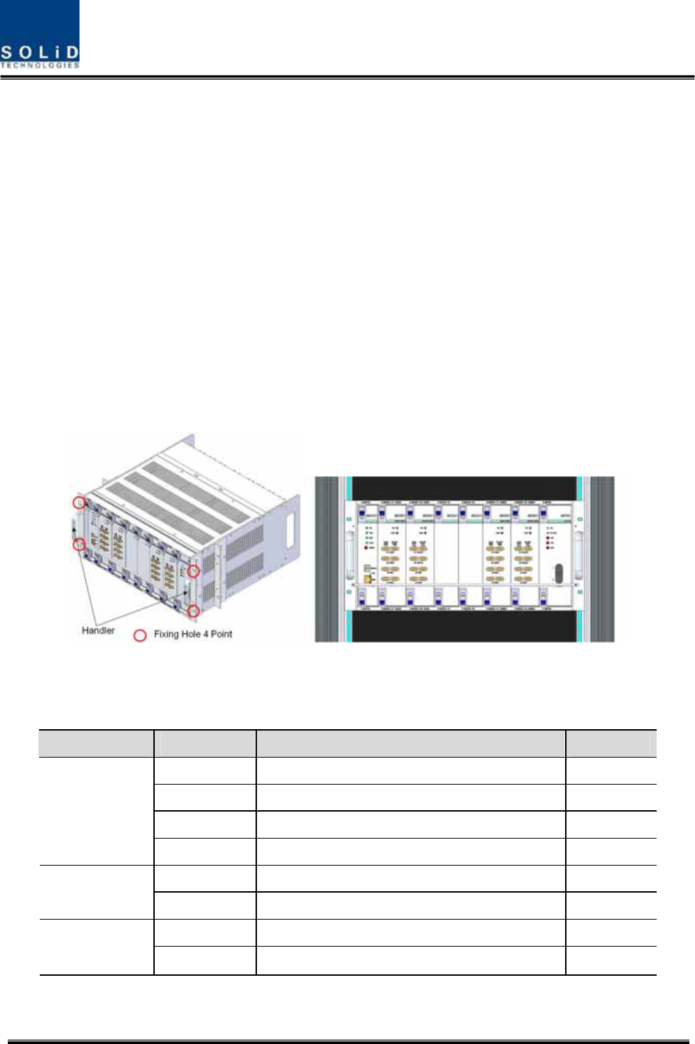
5.1 BIUInstallation
5.1.1 BIUShelfInstallation
Generally,theBIUisinstalledina19”standardrack.Thisunithashandlesoneachsideforeasy
placement.Withtwomountingholesoneachside,youcanfirmlyfixtheunitintoa19”rack.
Figure5.1–RACKInstallation
BIUhasthefollowingcomponents:
No.UnitDescriptionRemark
ShelfIncludingMainBoard,19”,5U1EA
MPSUOperate‐48VdcInput 1EA
MCPUWithEthernetPortandUSBPort1EA
CommonPart
PowerCable‐48VdcInputwithtwolugterminal 1EA
MCDU‐ 1EA
SISOSlot
MDBUTwoamongMDBUUpto2EA
MCDU‐ 1EA
MIMOSlot
MDBUTwoamongMDBUUpto2EA
Basically,theframeoftheBIUhasslotsequippedwithanMPSUtosupplydeviceswithpoweran
Confidential&Proprietary59/122 SC‐DAS
MCPUtoqueryandcontrolstateofeachmoduleandaPowerCabletosupplypowerfromexternal
rectifiers.
Inaddition,therareslotsfortheMDBUswhichprovideservicesfordesiredband(Optional)andthe
MCDUtocombineanddivideTX/RXsignalsforeachSISOandMIMOslots
5.1.2 BIUPowerCabling
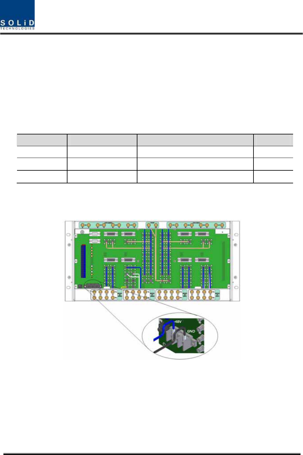
BIUrequires‐48VDCinputpower.ConnectDCcablefromthepowersupplytotheTerminalBlock
seenattherearofBIU.
TerminalColorofcableDescriptionRemark
‐48VBluecolor‐
GNDBlackcolor‐
NCNotConnected‐
Beforeconnectingthepowerterminal,youneedtoconnect"+"terminaloftheDVMprobewiththe
GNDterminalandthenconnect"–"terminalwith‐48Vtoseeif“‐48Vdc”voltageispresent.After
confirmingthis,connectthepowerterminalwiththeterminaloftheterminalblockseenbelow.
Figure5.2–Powerinterfacediagrm

Confidential&Proprietary60/122 SC‐DAS
NotethatBIUdoesnotoperateifthe"+"terminalandthe"–"terminalofthe‐48Vpowerare
reversed.
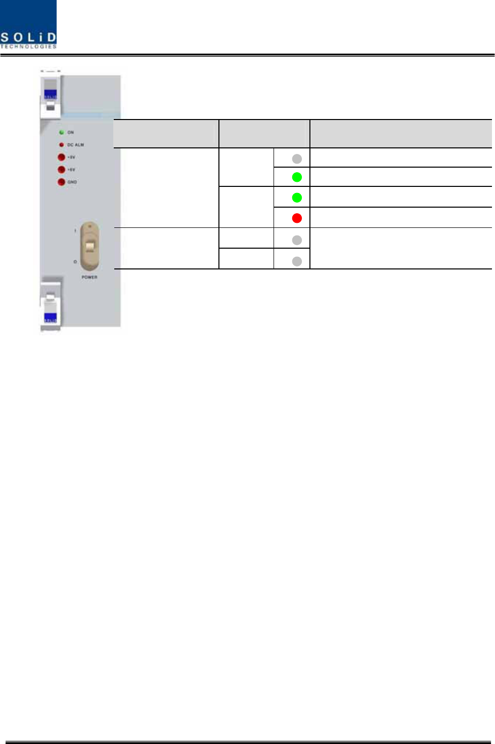
Whenyouconnect‐48VpowertotheBIU,usetheON/OFFswitchoftheMPSUlocatedatthefront
ofBIUtocheckthepower.
Confidential&Proprietary61/122 SC‐DAS
Figure5.3–PSULEDindicatorinformation
PowerSwitchLEDDescription
Abnormal,NotsupplyPower‐48Vdc
ON
Normalsupplypower‐48Vdc
NormalStatus
O
DCALM
FailureofoutputPower
ON
I
DCALM
NormalStatus
Confidential&Proprietary62/122 SC‐DAS
5.1.3 BIU/RFinterface
TheBIUcanbeconnectedwithaBi‐DirectionalAmplifierorBaseStationTranceiver.
ToconnecttheBIUwithaBDA,youneedtouseaduplexeroracirculatortoseparateTX/RXsignals
fromeachother.
TheBIUcanfeedexternalTX/RXsignalsfromtheBackPlane.
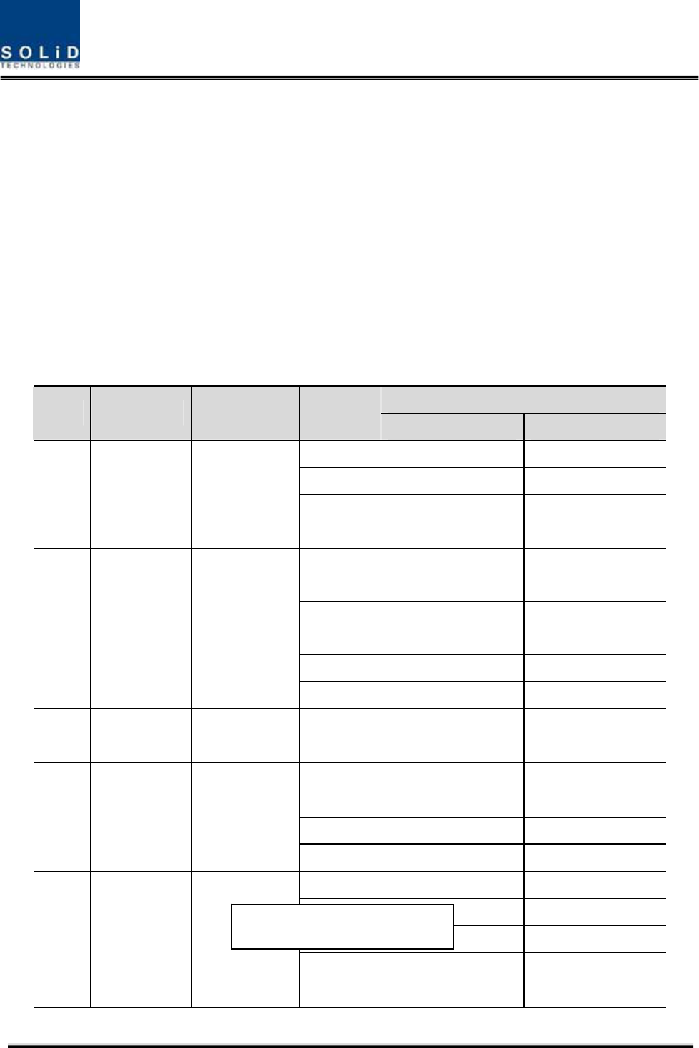
UsingadualbandMDBU,theBIUcaneasilyaccomodateallfrequencybands.Asseeninthetable
below,theMDBUisdividedintoSingleandDualBandmodulesandeachunitcanbeconnected
withtwocarriersignalsperband.AttherearoftheMDBU,4portsrepresenttheinputsforthe
frequencybands.Thefollowingtableshowssignalstobefedtocorrespondingports:
In/outRFPort
NoUnitnaming
Description
TXRX
Port#11900PTX(1930~1995MHz)1900PRX(1850~1915MHz)
Port#21900PTX(1930~1995MHz)1900PRX(1850~1915MHz)
Port#3850CTX(869~894MHz)850CRX(824~849MHz)
1
1900P+850C
MDBU
DualBand
1900P:2Port
850C:2Port
Port#4850CTX(869~894MHz)850CRX(824~849MHz)
Port#1700LTETX(728~756MHz)
700LTERX(698~716MHz,
777~787MHz)
Port#2700LTETX(728~756MHz)
700LTERX(698~716MHz,
777~787MHz)
Port#3AWS‐1TX(2110~2155MHz)AWS‐1RX(1710~1755MHz)
2
700LTE+AWS‐1
MDBU
DualBand
700LTE:2Port
AWS‐1:2Port
Port#4AWS‐1TX(2110~2155MHz)AWS‐1RX(1710~1755MHz)
Port#11900PTX(1930~1995MHz)1900PRX(1850~1915MHz)
3
1900P
MDBU
SingleBand
1900P:2PortPort#21900PTX(1930~1995MHz)1900PRX(1850~1915MHz)
Port#1900ITX(935~940MHz)900IRX(896~901MHz)
Port#2900ITX(925~940MHz)900IRX(896~901MHz)
Port#3800PSTX(851~869MHz)800PSRX(806~869MHz)
4
900I+800I
MDBU
DualBand
900I:2Port
800I:2Port
Port#4800PSTX(851~869MHz)800PSRX(806~869MHz)
Port#11900PTX(1930~1995MHz)1900PRX(1850~1915MHz)
Port#21900PTX(1930~1995MHz)1900PRX(1850~1915MHz)
Port#3AWS‐1TX(2110~2155MHz)AWS‐1RX(1710~1755MHz)
5
1900P+AWS‐1
MDBU
DualBand
1900P:2Port
AWS‐1:2Port
Port#4AWS‐1TX(2110~2155MHz)AWS‐1RX(1710~1755MHz)
6700PS+800PSDualBandPort#1700PSTX(763~775MHz)700PSRX(793~805MHz)
On the loadmap
Confidential&Proprietary63/122 SC‐DAS
Port#2700PSTX(763~775MHz)700PSRX(793~805MHz)
Port#3800PSTX(851~869MHz)800PSRX(806~869MHz)
MDBU700PS:2Port
800PS:2Port
Port#4800PSTX(851~869MHz)800PSRX(806~869MHz)
Port#1900ITX(929~941MHz)900IRX(896~902MHz)
7
900I
MDBU
SingleBand
900I:2PortPort#2900ITX(929~941MHz)900IRX(896~902MHz)
VHF
Tx(136~174MHz)
VHF
Rx(136~174MHz)
8
VHF+UHF
MCDU
DualBand
VHF+UHF:1Port
Port#1
UHF
Tx(380~512MHz)
UHF
Rx(380~512MHz)
AttherearofBIU,TxinputandRxoutputportsareseenforeachMDBU.Thenameofalltheports
aresilkscreenedas"#1,#2,#3and#4."Fromthetableabove,youneedtofeedcorrectsignalstothe
inputandoutputportsofthecorrespondingMDBU.
Figure5.4–BIURFinterfacediagram
Foreachport,TXandRXsignalsareseparatedfromeachother.Itisnotnecessarytoterminate
unusedportsunlessyouwantto.
BIUinterfacewithBasestationTransceiver
Basically,theBIUhasseparateTXandRXportssoyouhaveonlytoconnecttheinputandoutput
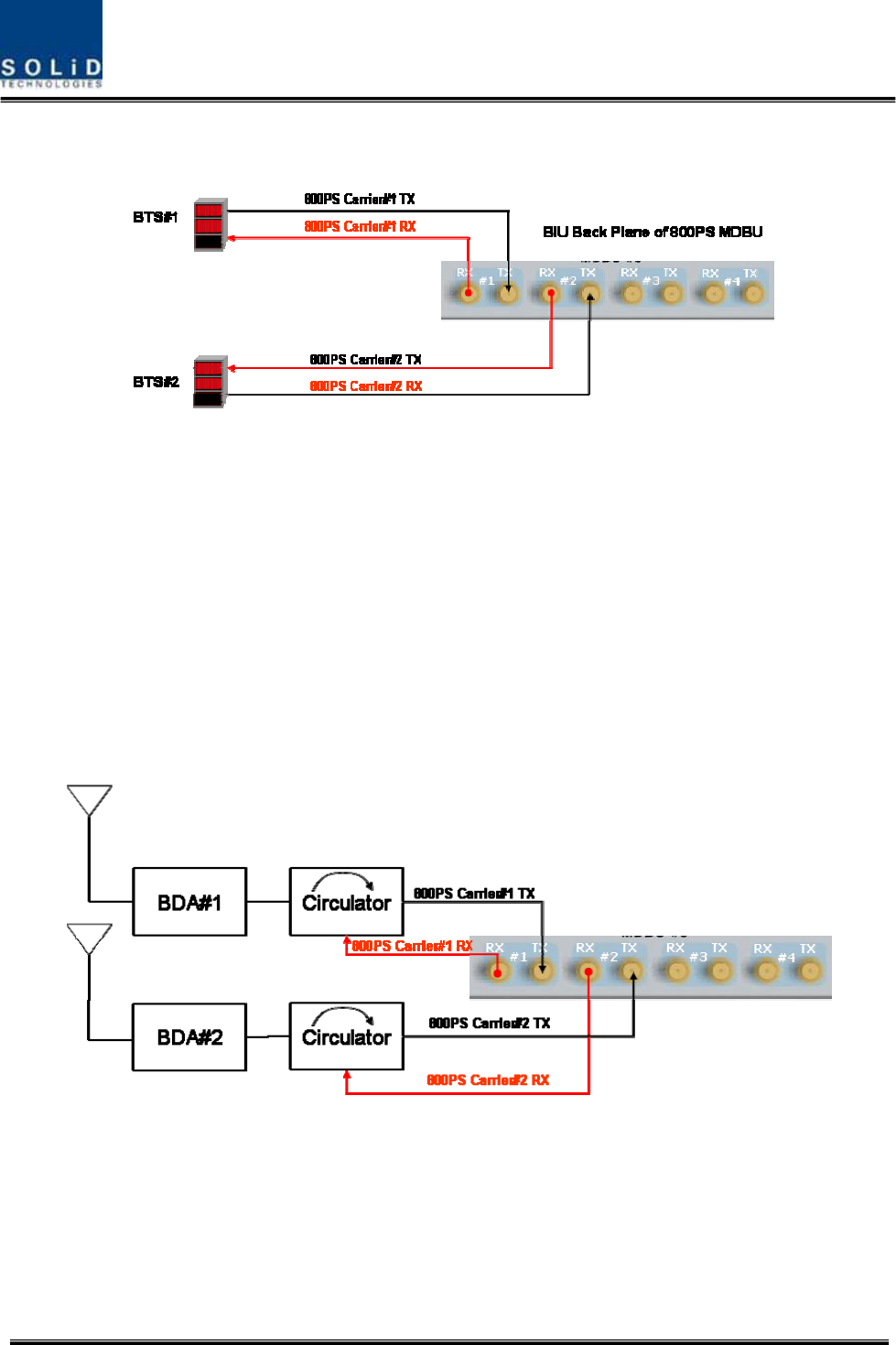
Confidential&Proprietary64/122 SC‐DAS
ports.
Figure5.5–BTS/BIUconnections
Usingaspectrumanalyzerorpowermeter,youneedtochecksignalssentfromBTSTX.Ifthesignals
exceedinputrange(‐20dBm~+10dBm),youcanconnectanattenuatorbetweentheBTSandBIUto
bringthesignallevelintorange.
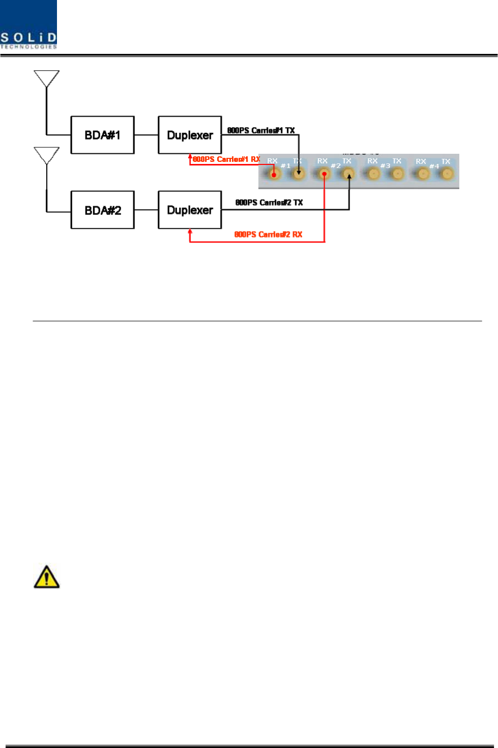
BIUinterfacewithBi‐DirectionalAmplifier
SincetheBIUisSimplexformat;youneedtoun‐duplextheBDAsignaltoproperlyconnectittothe
BIU.
Usingeitherduplexeroracirculator,youcanseparateTX/RXsignalscomingfromtheBDA
Figure5.6–BDAInterfaceusingCirculator
Confidential&Proprietary65/122 SC‐DAS
Figure5.7–BDAInterfaceusingDuplexer
TheBIUwillworkwiththeBDAineitherofthemethodsabove.TXsignallevelfromtheBDAmustbe
verifiedthatitiswithinrangeoftheBIU.
GiventheBIUTXinputrange(‐20dBm~+10dBm/Totalperport),verifyitiswithintheinput

Confidential&Proprietary66/122 SC‐DAS
range,beforeconnectingtheports.
5.1.4 MDBUinstallation
MDBUisdesignedtobeinsertedintoanyslot.
ABIUcanbeequippedwithatotaloffourMDBUs.IfonlyoneMDBUisinserted,youneedtoinsert
BLANKcardsintotheotherslots.
IfyoudonotterminateinputandoutputportsoftheMCDU,whichcombinesTXsignalsand
dividesRXsignals,itwillcauseoutofbandspurioussignals.MakesuretoinsertMDBUBLANKcards
Confidential&Proprietary67/122 SC‐DAS
intotheMDBUslots.
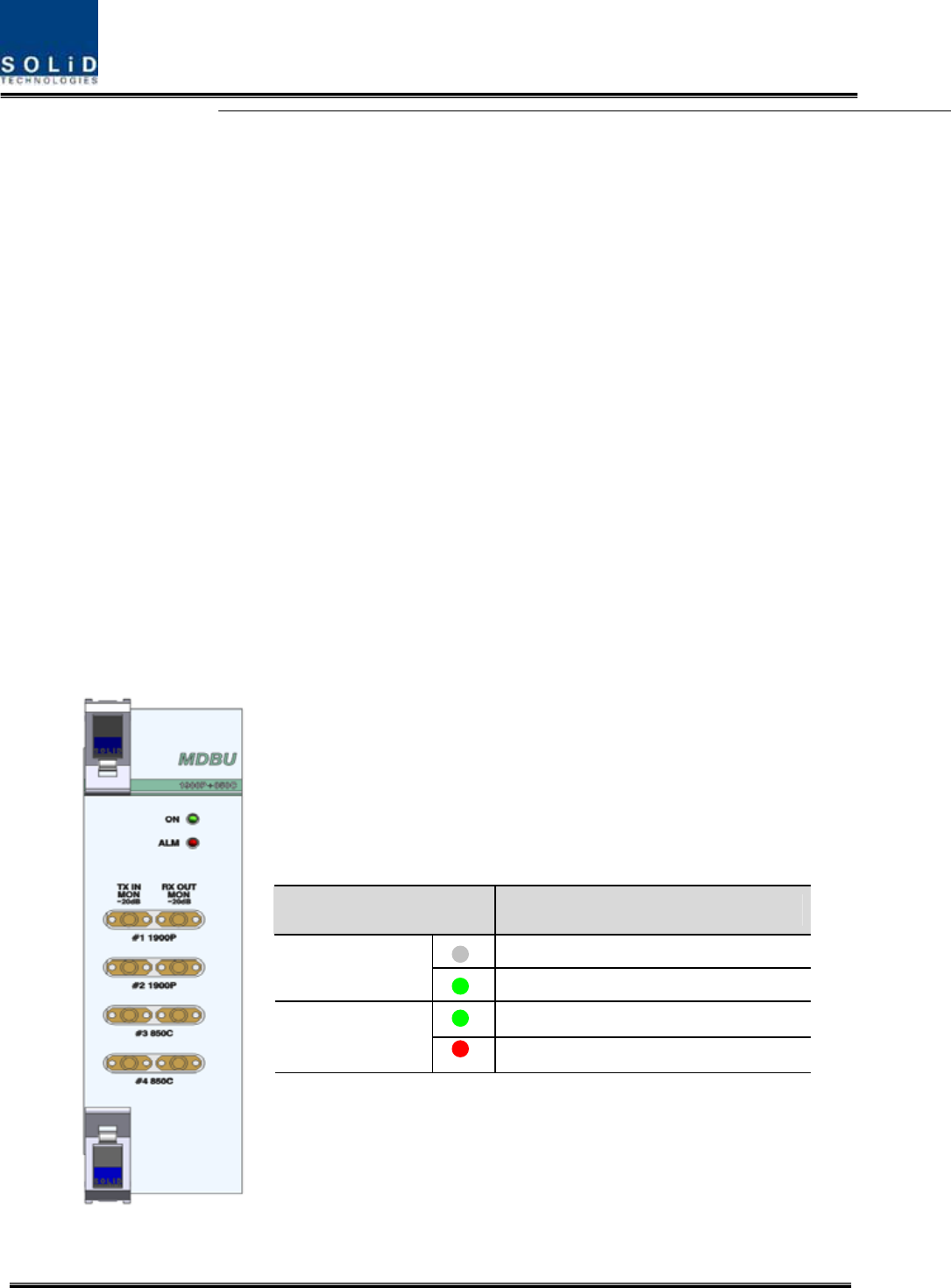
WhenanMDBUisinsertedintotheBIU,LEDsatthefrontpanelwillshowthefollowinginformation:
Figure5.8–MDBULEDindicatorinformation
LEDDescription
Powerisnotsupplied.
ON
Powerissupplied.
NormalOperation
ALM
AbnormalOperation
Confidential&Proprietary68/122 SC‐DAS
MONITORSMAportseenatthefrontpaneloftheMDBUallowsyoutocheckthecurrentlevelofTX
inputandRXoutputsignalsinservicewithoutaffectingmainsignals.
TXMONis‐20dBbelowTXInputpowerandRXMONis‐20dBbelowRXOutputpoweraswell.
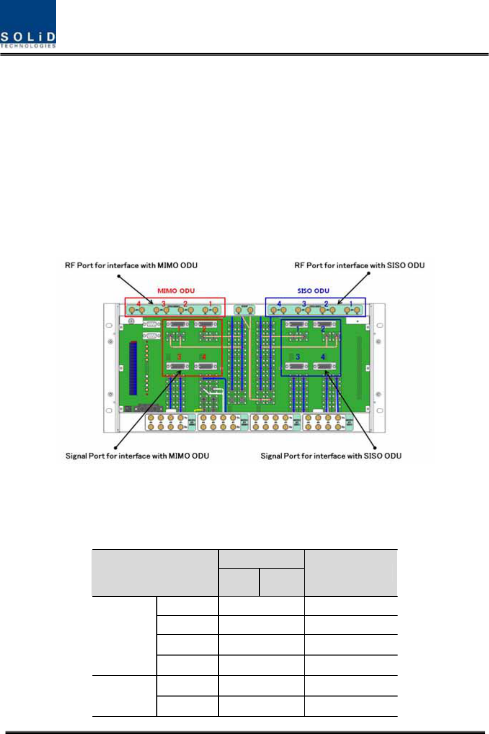
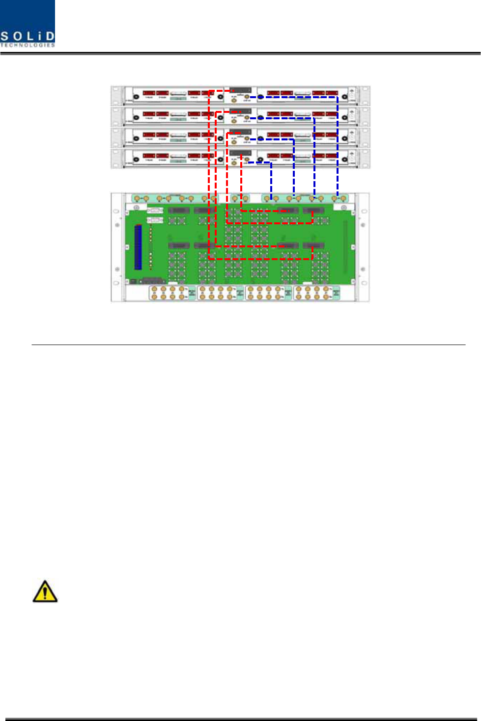
5.1.5 ODUInterface
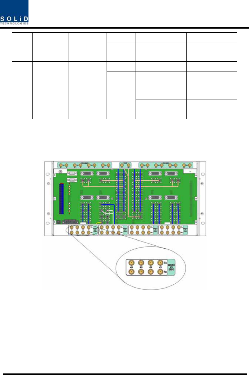
TheBIUsupportsuptofourODUsperplatform.AttherearofBIU,eightRFinputandoutputports
fortheODUsaswellasfourpowerportsforpowersupplyandcommunicationareprovided.Asyou
connecttheODUs,theBIUrecognizestheODUthatisconnectedwithBIUautomatically
Figure5.9–InterfaceportbetweenBIUandODU
AttherearpartoftheODU,thenumberofRFPortsandSignalPortsareprintedinorder.Itsagood
ideatolabeltheseincaseadditionalODUsareneeded.
RFPort
ODUNumbering
TXRX
SignalPort
ODU1#1SISO_ODU#1
ODU2#2SISO_ODU#2
ODU3#3SISO_ODU#3
ODUSISO
ODU4#4SISO_ODU#4
ODU1#1MIMO_ODU#1
ODUMIMO
ODU2#2MIMO_ODU#2

Confidential&Proprietary69/122 SC‐DAS
ODU3#3MIMO_ODU#3
ODU4#4MIMO_ODU#4
Confidential&Proprietary70/122 SC‐DAS
Figure5.10–CablinginterfacediagrambetweenBIUandODU
ForunusedRFPortsforODUexpansion,makesuretoterminatethemusingSMATerm.

Confidential&Proprietary71/122 SC‐DAS
WheninstallinganODUabovetheBIU,itisrecommendedtoleaveatleast1RUofspace
betweenthetwo.HeatfromBIUrisesandcoulddamagetheODU.
Confidential&Proprietary72/122 SC‐DAS
5.1.6 BIUpowerconsumption
ThetablebelowshowspowerconsumptionoftheBIU:
PartUnitConsumptionPowerRemark
Shelf
MCPU
CommonPart
MPSU
4.8W
MCDU‐ 2.4W
1900P+850C16W
700LTE+AWS‐116W
1900P12W
900I+800I16W
1900P+AWS‐1‐
700PS+800PS‐
MDBU
900I‐
TheBIUsuppliespowerforODU.WhenyouwanttocalculatetotalpowerconsumptionoftheBIU,
youneedtoaddpowerconsumptionoftheODUtothetotalvalue.
PowerconsumptionofODUisgiveninthelaterparagraphdescribingODU.
On the loadmap

Confidential&Proprietary73/122 SC‐DAS
5.2 ODUInstallation
ODUshouldbe,inanycase,putonthetopofBIU.ThisunitgetsrequiredpowerandRFsignalsfrom
BIU.ThefollowingtableshowscomponentsofODU:
No.UnitDescriptionRemark
ShelfIncludingMainBoard,19”,1U1EA
RFCableSMA(F)toSMA(F),400mm2EA
CommonPart
SignalCable3Row(26P_F)to3Row(26P_M),650mm1EA
OptionalPartDOUOpticalModulewith4OpticPortUpto2EAtobe
inserted
5.2.1 ODUShelfInstallation
TheODUchassisis1RUinheightand19”wide.Itshouldbeinsertedintoa19”standardrackand
placedabovetheBIUleavinga1RUgapbetweentheODUandtheBIU.
5.2.2 ODUPowerCabling
TheODUgetspowerfromtheBIU.
Whenyouconnecta3‐Row,26‐pinD‐SUBSignalcablefromBIUandinstallDOU,LEDonthefront
panelislit.ThroughthisLED,youcancheckstatevaluesofLDandPDofDOU.
5.2.3 ODUOpticCabling
TheODUmakesRF‐opticalconversionofTXsignalsaswellasoptical‐RFconversionofRXsignals.
TheODUcanbeequippedwithuptotwoDOUs.OneDOUsupportsfouropticalportsandone
opticalportcanbeconnectedwithanROU.Optionally,onlyopticalport4canbeconnectedwith
OEUforODU1andODU2.ODU3.ODU4cannotconnectwithOEU.
AsWDMisusedintheDOU,theunitcanconcurrentlysendandreceivetwodifferentwavelengths
(TX:1310nm,RX:1550nm)throughonestrandoffiber.TheDOUhasSC/APCfiberconnectors.
Confidential&Proprietary74/122 SC‐DAS
Figure5.11–SC/APCfibertermination
Foropticaladaptor,SC/APCtypeshouldbeused.Topreventcontaminationofthefiberend,itshould
becoveredwithacapwhennotinstalled.TheSC/APCconnectorsshouldbecleanedwithalcohol
priortoinstallation.
5.2.4 DOUinstallation
UptotwoDOUscanbeinstalledinanODUchassis.TheDOUmoduleisaPluginPlaytype.
WhenyouinsertaDOUintheODU,inserttheunitintotheleftDOU1slotfirst.Theslotnumberissilk
screenedattheleft.
ThefollowingfigureshowsinstallationdiagramoftheODUwithoneDOUinsertedinit.
ThefollowingfigureshowsinstallationdiagramofODUwithtwoDOUsinsertedinit.
Figure5.12–ODUrearviewwithDOUsinserted
Confidential&Proprietary75/122 SC‐DAS
WhenyouinsertDOUintoODU,inserttheunitintotheleftDOU1slotfirst.InsertaBLANK
UNITintheunusedslot.
5.2.5 ODUPowerconsumption
TheODUgetspowerfromtheBIU.OneODUcanbeequippedwithuptotwoDOUs.Dependingon
howmanyDOUsareinstalled,powerconsumptionvaries.Thetablebelowshowspower
consumptionoftheODU:
PartUnitConsumptionPowerRemark
ODU_4DOU1EA14W

Confidential&Proprietary76/122 SC‐DAS
ODU_8DOU2EA28W
Confidential&Proprietary77/122 SC‐DAS
5.3 ROUInstallation
5.3.1 ROUEnclosureinstallation
TheROUenclosurehastwooptions.OnemeetsNEMA4standardandtheotherisnotwaterproofor
dirtproof.TheROUcanbemountedonaWalleasily.Rackmountingisalsopossibleusingspecial
frame.Thereare3differenttypesandtheywillbeexplainedlaterinthischapter.TheROUconsists
ofanMRUandanARU.Theirdimensionsarethesame.
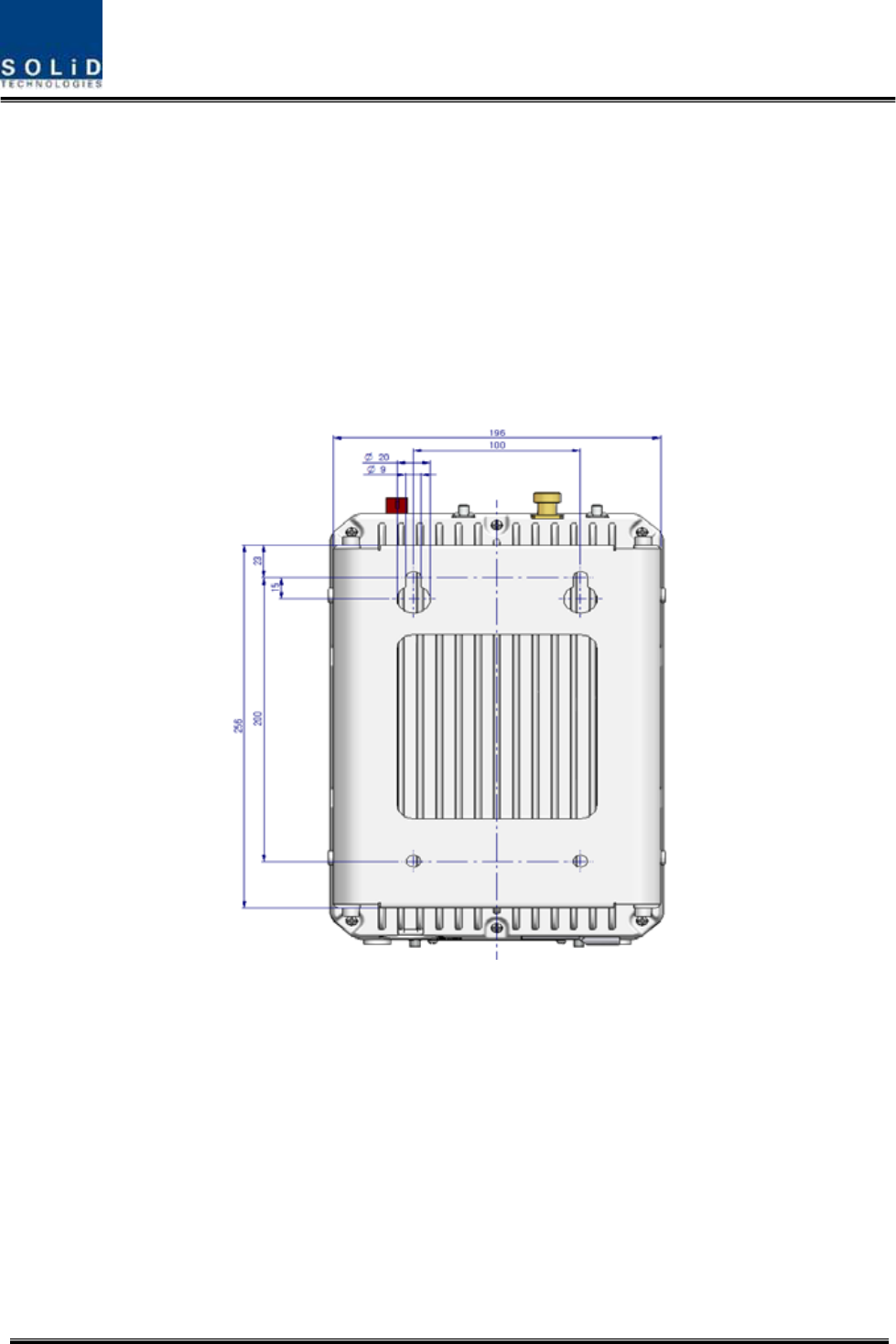
ThefollowingshowsthedimensionofthemountingholesfortheWallMountBracket.
Figure5.13–WallmountdimensionsfortheROU
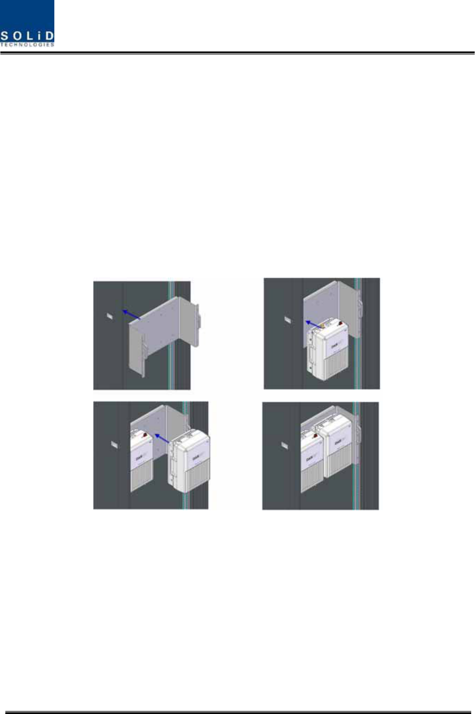
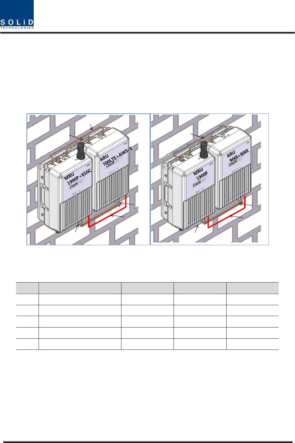
ROUWallMountInstallation
TherearetwowaytoinstalltheROUonthewall.OneistoinstallROUsonthewallsidebyside,the
otherisstacktheARUabovetheMRU.
Type1:SidebySideinstallation
InstallM8mountingScrewsroughlyhalfwayin,insertthewallmountbracketoverthe2screwsand
secureitwiththelast2screws.
Forconvenience,theWallMountBrackethasmountingholestoletyoueasilymountanenclosure.
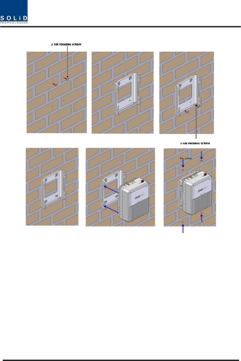
Confidential&Proprietary78/122 SC‐DAS
ScrewtheM6WrenchBoltsbyhalfateachsideoftheHeatsinkenclosure.
Figure5.14–ROUinstallationproceduresidebyside
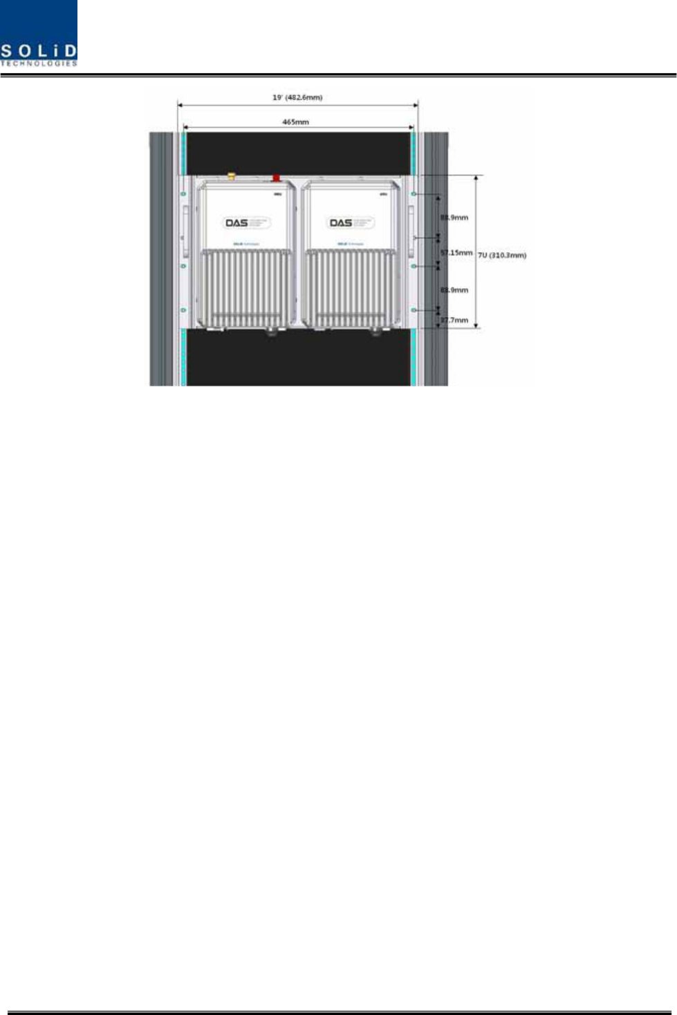
PlacetheenclosurewiththeM6BoltonthemountinggrooveandmounttheM6WrenchBoltsinto
theremainingmountingholes.
Inthiscase,youwilluse4M6WrenchBolts.
Confidential&Proprietary79/122 SC‐DAS
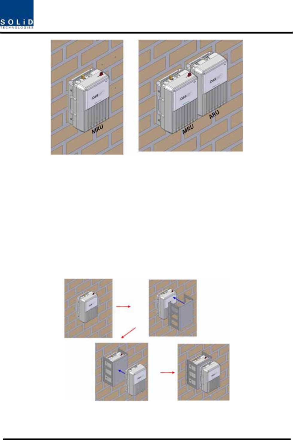
Figure5.15–ROUinstallationdiagramsidebyside
ForconnectingcablesbetweenMRUandARUeasily,theMRUshouldinstallonleftsideofARU.
Type2:stackedinstallation
IfspaceprohibitstheMRUandARUfrombeingmountedsidebyside,theunitscanbeinstalledin
astackedconfiguration.
Stackingtheunitrequiresaspecialbaracketforstackedinstallation
First,installtheMRUonthewall,theninstallthebracketforstackedinstallationontheMRU.Finally
installtheARUonthebracket.
Completedinstallationdiagramisasfollows
Figure5.16–ROUinstallationprocedureforstackedmounting
Confidential&Proprietary80/122 SC‐DAS
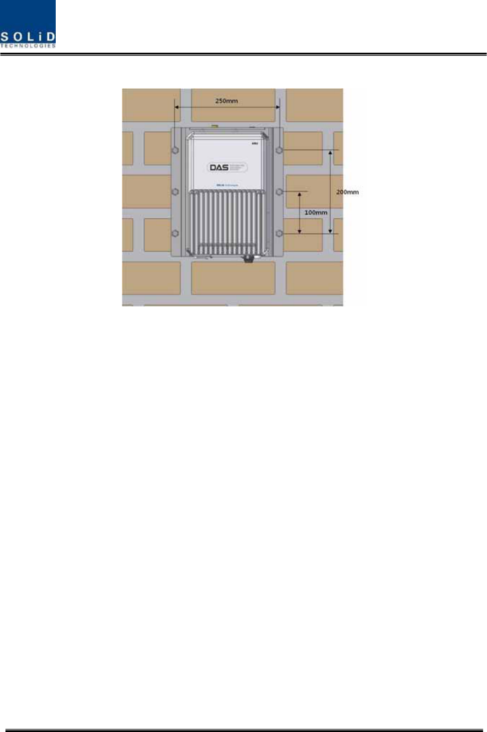
Thefollowingshowsdimensionofthemountingpointforthestackedbracket.
Figure5.17–ROUinstallationdiagramforstackedmounting
Confidential&Proprietary81/122 SC‐DAS
ROURackMountInstallation
Therearetwowaystoinstallrackmount.OneistoinstallROUsontherackvertically:theotheristo
installROUsontherackhorizontally
Type1:Verticalinstallationontherack
Forvertcalinstallation,averticalbracketisneeded.
First,installbracketforverticalinstallationontherack
Second,mountMRUontheleftsideoftheinstalledbracket
Third,mountARUontherightsideoftheinstalledbracket
Completedinstallationdiagramisasfollows
Figure5.18–ROUinstallationprocedureforverticalrack
Thefollowingshowsdimensionofthemountingpointforverticalinstallation
Confidential&Proprietary82/122 SC‐DAS
Figure5.19–ROUinstallationdiagramforverticalrack
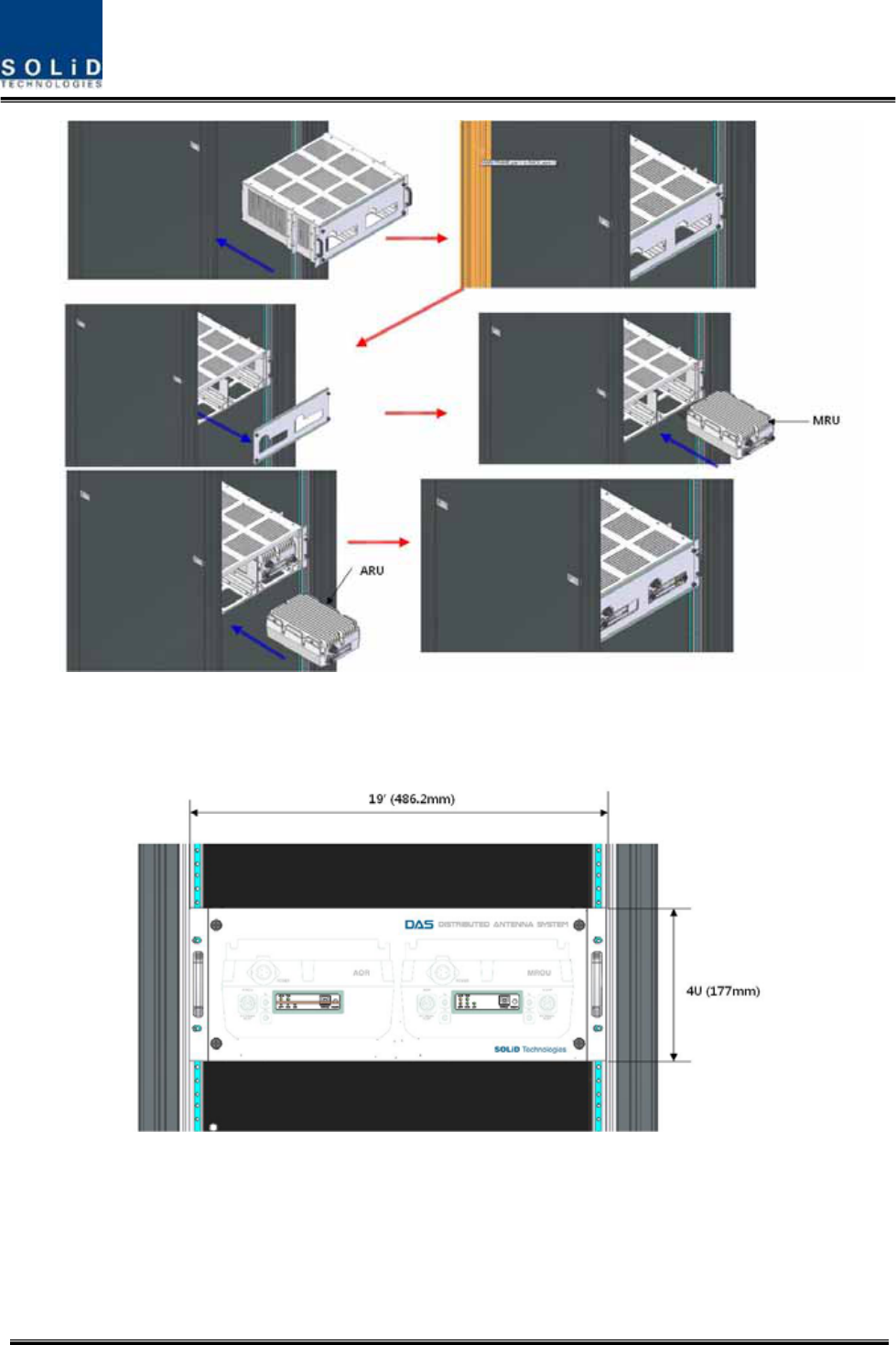
Type2:Horizontalinstallationontherack
ForHorizontalinstallation,horizontalbracketisneeded.Unlikeverticalinstallation,theMRUis
mountedontherightoftheinstalledbracketfirstandthenARUisinstalledtotheleftofMRU
First,installbracketforhorizontalinstallationontherack
Second,openthefrontcoverofhorizontalbracket
Third,mountMRUontherightsideoftheinstalledbracket
Fourth,mountARUontheleftsideoftheinstalledbracket
Finally,closethefrontcoverofhorizontalbracket
Completedinstallationdiagramisasfollows
Confidential&Proprietary83/122 SC‐DAS
Figure5.20–ROUinstallationprocedureforhorizontalrack
Thefollowingshowsdimensionsofthemountingpointforhorizontalinstallation
Figure5.21–ROUinstallationdiagramforhorizontalrack
Confidential&Proprietary84/122 SC‐DAS
ROUcomponents
TheROUhasthefollowingcomponents:
No.UnitDescriptionRemark
EnclosureIncludingWallcradle1EA
MRU
PowerCable
‐Connectorwith3holetoAC120plug(AC)
‐Connectorwith2lugtermination(DC)
1EA(Opticalfor
ACorDC)
EnclosureIncludingWallcradle1EA
PowerCable
‐Connectorwith3holetoAC120plug(AC)
‐Connectorwith2lugtermination(DC)
1EA(Opticalfor
ACorDC)
RFcablefor
optical
‐TwoRFcablesandonesignalcable
ARU
RFcablefor
antenna
‐TwoRFcables
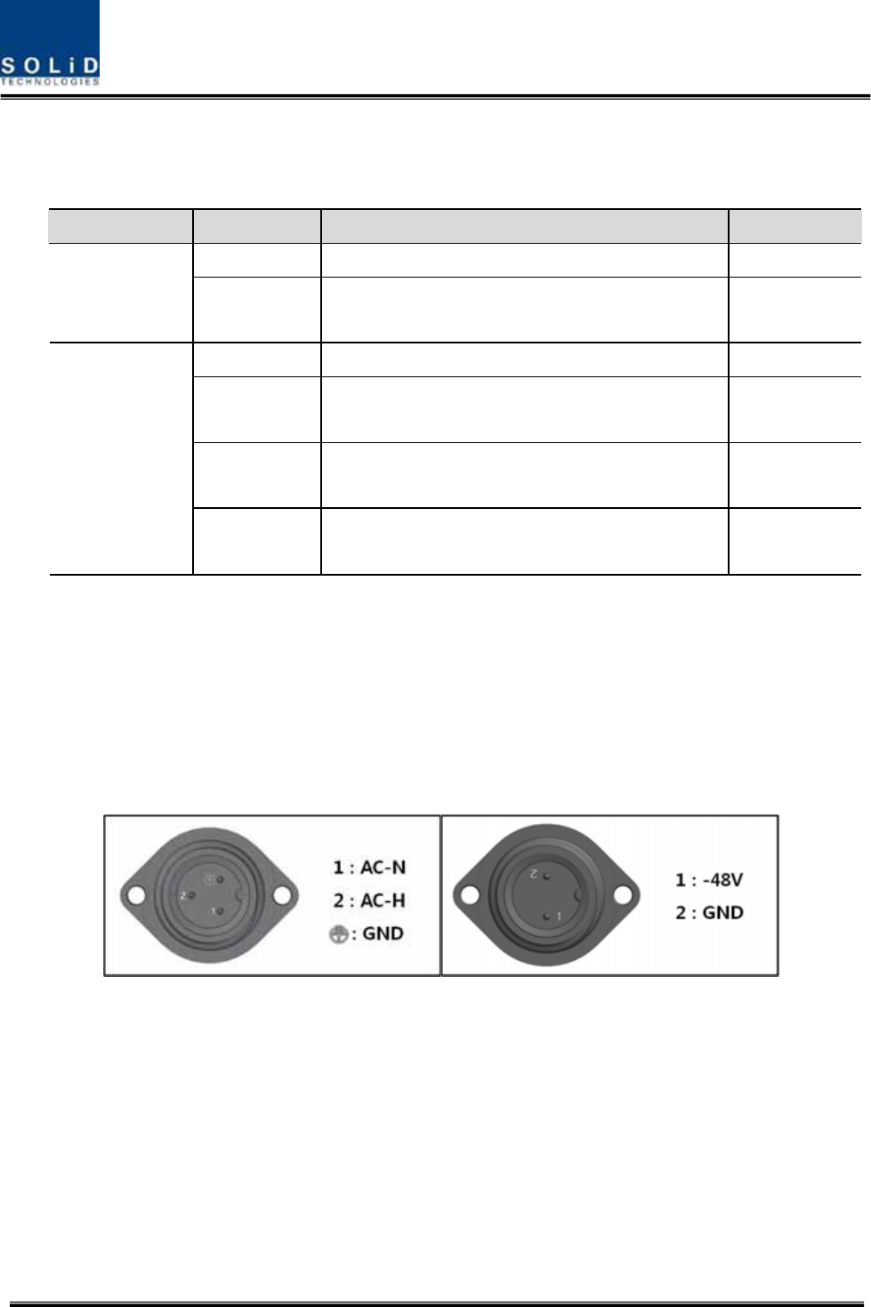
5.3.2 ROUPowerCabling
TheROUsupportsbothofDC‐48VandAC120Vinputpower.ThetypeofinputpowerfortheROUis
alreadydeterminedatthefactory.TheROUisshippedwiththecorrectpowercableinthepackage
box.SeetheULnameplateoftheROUtodeterminetheinputpowertypeoftheROUorseethe
powerconnectorinthebelowpicture.Youshouldorderthetypeofinputpowerasyourapplication.
(a)AC/DC(b)DC/DC
Figure5.22–ROUPowerPortview
Checkifyourpowercordconnectoristhesameasoneseeninthetableabove.TheROUdoesnot
havepowerswitchtopoweron/off.PowersupplyisonwhencordispluggedintotheACsource.
Confidential&Proprietary85/122 SC‐DAS
5.3.3 OpticalCabling
TheMRUmakestheoptical‐RFconversionofTXsignalsfromuppertheODUandOEUaswellasthe
RF‐ opticalconversionofRXsignals.TheMRUhasoneopticalmoduleinit.AsWDMisusedinthe
R_OPTmodule,twoseparatewavelengths(TX:1310nm,RX:1550nm)canbesent/receivedwithone
fiberstrandatthesametime.TheMRUhasSC/APCconnectors.
Topreventthefiberinterfacefrombeingmarredwithdirt,itshouldbecoveredwithacapwhennot
installed.Fiberconnectorsshouldbecleanedalcohocoltoremovedirtbeforeinstallation.
Figure5.23–ROUopticalPortview
OnlytheMRUhasopticalport;thereisnoopticalportontheARU
5.3.4 GNDTerminalConnection
TheROUhasoneGNDterminalportonbottomside,asshownbelow

Confidential&Proprietary86/122 SC‐DAS
Figure5.24–ROUGNDPortview
- TakeofftheGNDterminalportfromtheenclosureandconnecttothegroundcable.
Thenreconnectittotheenclosure
- TheoppositeendofthegroundcableshouldconnecttothecommunicationGNDof
building
- ThegroundlugisdesignedmeetingtheSQ5.5standard
5.3.5 CoaxialcableandAntennaConnection
- ThecoaxialcableswhichareconnectedtoDASconnecttoantennaportoftheROU.
Beforeconnection,checktheVSWRofthecoaxialcableusingaSiteMastertoverify
whetheritiswithintolerance.
- TheReturnlossshouldbebetterthan15dBorVSWRshouldbebelow1.5:1.
- Makesuretheantennaconnectoristightenedproperlyandfreeofanydirtorinsects.
- TheantennaconnectedtotheROUisonlyforinbuildinguse.
- OnlytheMRUhasanantennaport.TheARUtransmitsitssignalthroughRFcable
connectedtoboththeMRUandARU
Confidential&Proprietary87/122 SC‐DAS
5.3.6 LEDexplanationonROU
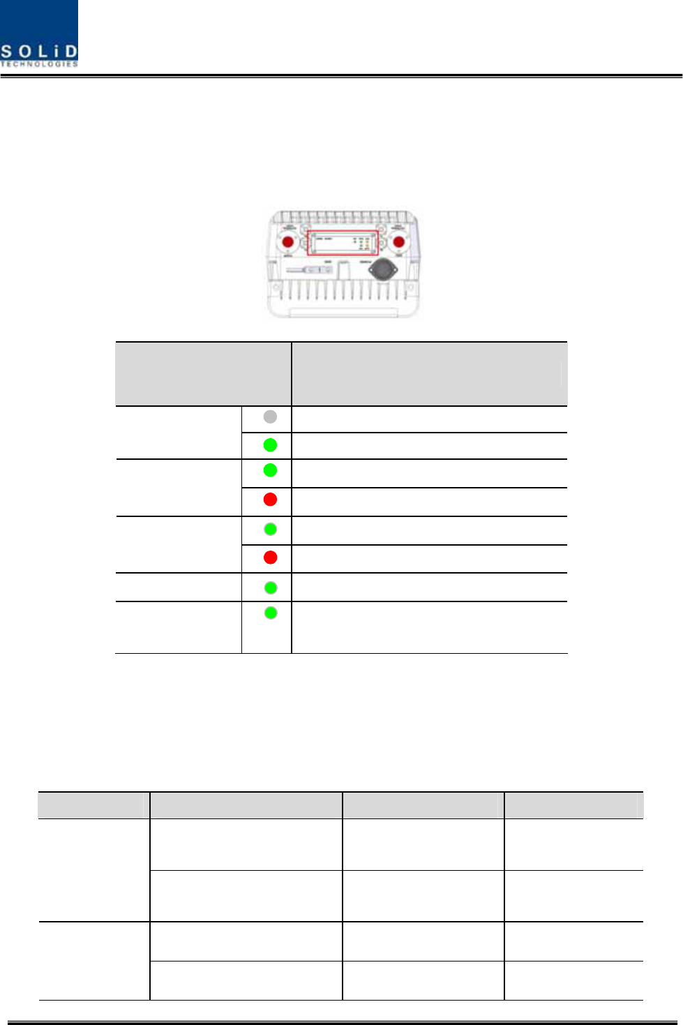
TheROUhasanLEDpanelatthebottomofROU.TheLEDindicatorisexplainedbelow
Figure5.25–ROULEDindicatorinformation
5.3.7 ROUPowerconsumption
ThefollowingtableshowspowerconsumptionoftheROU
PartUnitConsumptionPowerRemark
1900P+850CsupportingARU
700LTE+AWS‐150WDualBand
MRU
1900PsupportingARU
900I+800I45WSingleBand
700LTE+AWS‐140WDualBand
ARU
900I+800I44WDualBand
LEDDescription
Powerisnotsupplied
ON
Powerissupplied.
NormalOperation
ALM
AbnormalOperation
R‐OPTisnormaloperation
OPT
R‐OPTisabnormalOperation
TXDFlashingwhendatasendtoupperunit
RXD
Flashingwhendatareceivefromupper
unit
Confidential&Proprietary88/122 SC‐DAS
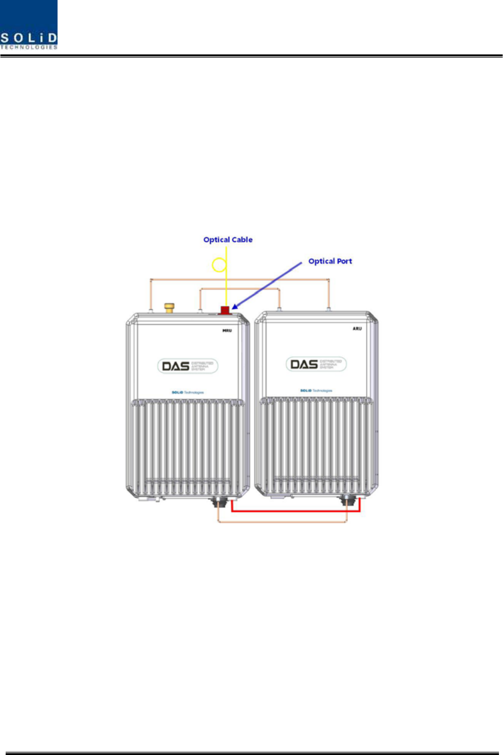
5.3.8 CableconnectionbetweenMRUandARU
MRUhasonlyantennaport,ARUoutputportshouldbeconnectedwithMRU.MRUtransmitall
frequencybandintooneantennaaftercombiningwithARUsignal
FigurebelowshowsconnectiondiagrambetweenMRUandARU
①
②
③
④
⑤
③
④
⑤
②
(a)MRU1900P+850C/ARU700LTE/AWS‐1(b)MRU1900P/ARU900I/800I
Figure5.26–CableconnectionbetweenMRUandARU
Cable
DescriptionMRUNameARUNameRemark
① CoaxialcableHighHigh
② CoaxialcableLowLow
③ CoaxialcableTXTX
④ CaaxialcableRXRX
⑤ SignalcableExternalportExternalport

Confidential&Proprietary89/122 SC‐DAS
5.4 OEUInstallation
OEUisusedtoexpandtheROUinamultibuildingenvironment.
TheOEUislocatedataRemoteCloset.AsitcanbeequippedwithuptotwoDOUs,youcan
expandatotalofeightROUs.
5.4.1 OEUchassisinstallation
TheOEUchassisis2RUinsizeandcanbeinsertedintoa19”StandardRack.TheOEUisinaRemote
Closet,providingopticalportsfortheROU.
ThefollowingtableshowspowerconsumptionofOEU:
No.UnitDescriptionRemark
ChassisIncludingEWDM,ERF,EPSU,ECPU,
19”,2U1EA
CommonPart
PowerCable‐48VdcInputwithtwolugterminal 1EA
OptionalPartDOUOpticalModulewith4OpticPortsUpto2EAtobe
inserted
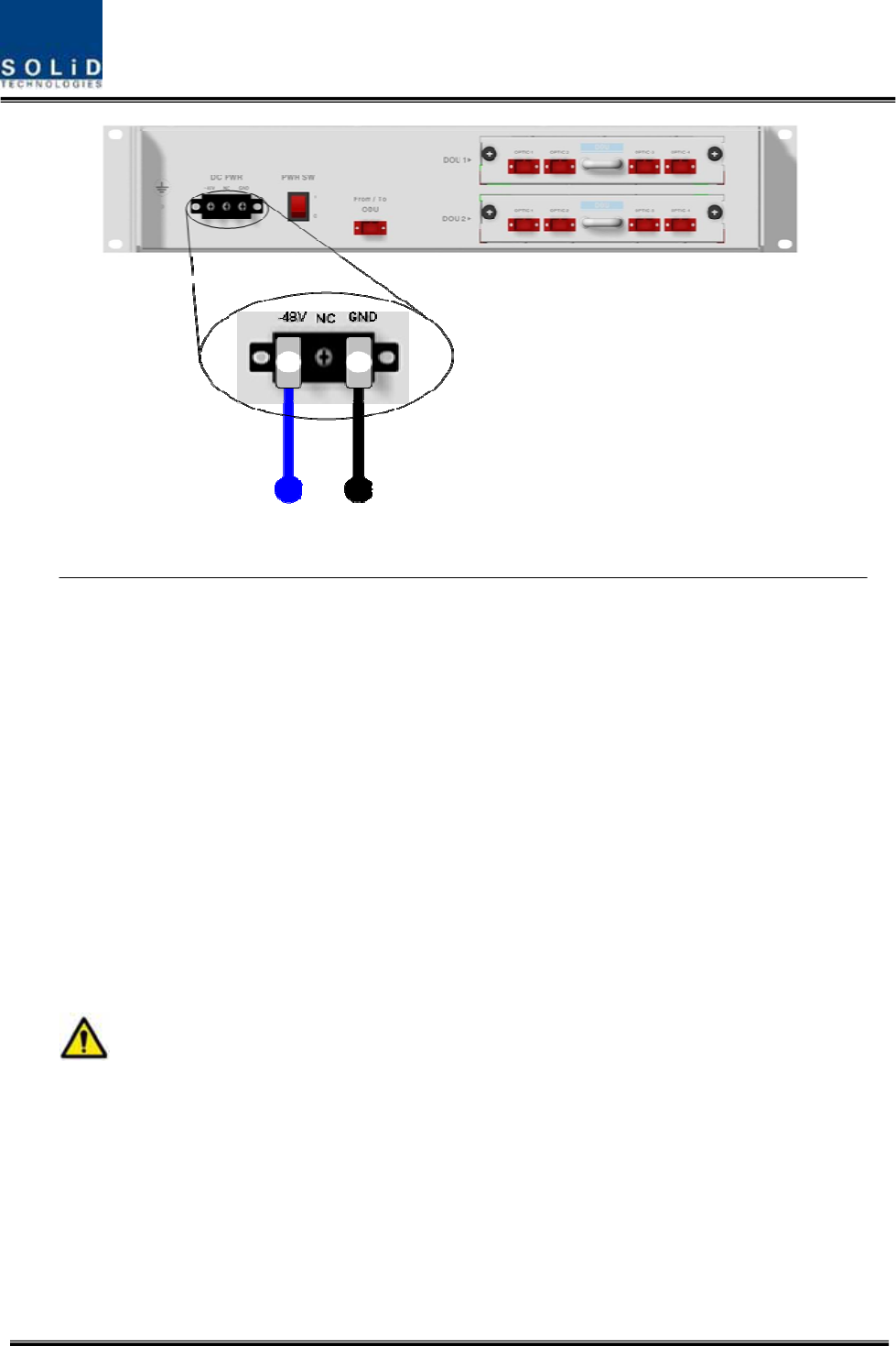
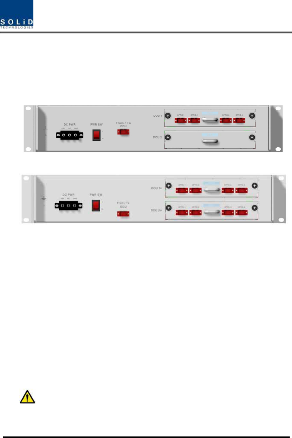
5.4.2 OEUPowerCabling
TheinputpoweroftheOEUis‐48VDC.YouneedtoconnectaDCcablewiththeTerminalBlockseen
attherearoftheOEU.
TerminalColorofcableDescriptionRemark
‐48VBluecolorInputrange:‐42to‐56Vdc
NCNotConnected
GNDBlackcolor
Beforeconnectingthepowerterminal,Verifythat‐48VDCispresentbyconnectingthepowersupply
toaDVMwith“‐“terminaltopositiveand“+”terminaltoGNDoftheDVM.Ifvoltageiscorrect,
connectthepowerterminalthroughtheterminalseenbelow.
Confidential&Proprietary90/122 SC‐DAS
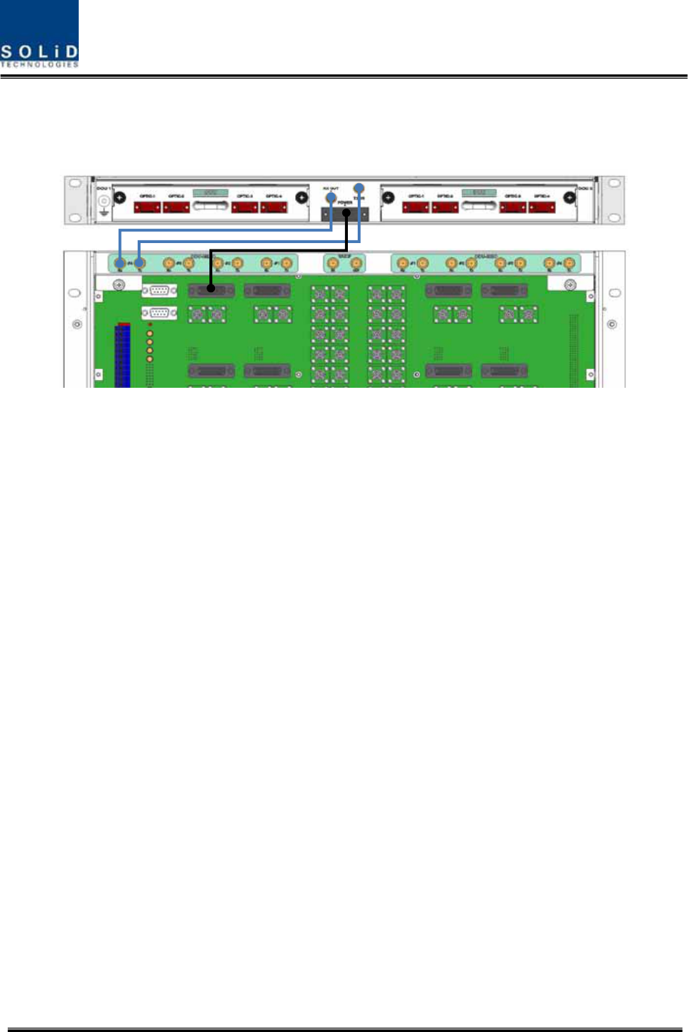
Figure5.26–OEUPowerinterfacediagram
NotethatOEUdoesnotoperateifthe“+”terminalandthe“–“terminalofthe‐48Vpower
supplyarereversed.
Confidential&Proprietary91/122 SC‐DAS
5.4.3 OEUOpticCabling
TheOEUisconnectedwiththeupperODU.WiththeDOUinsertedinit,theunitisconnectedwith
theROU.
HavingEWDMbuiltintheOEU,itmakestheRF‐opticalconversionofTXsignalsfromODUaswellas
theoptical‐RFconversionofRXsignals.Inaddition,theOEUcanbeequippedwithuptotwoDOUs.
OneDOUsupportsfouropticalportsandoneopticalportcanbeconnectedwiththeROU.With
WDMintheDOU,theunitcanconcurrentlysend/receivetwodifferentwavelengths(TX:1310nm,
RX:1550nm)throughonestrandoffiber.TheDOUhasSC/APCconnectors.
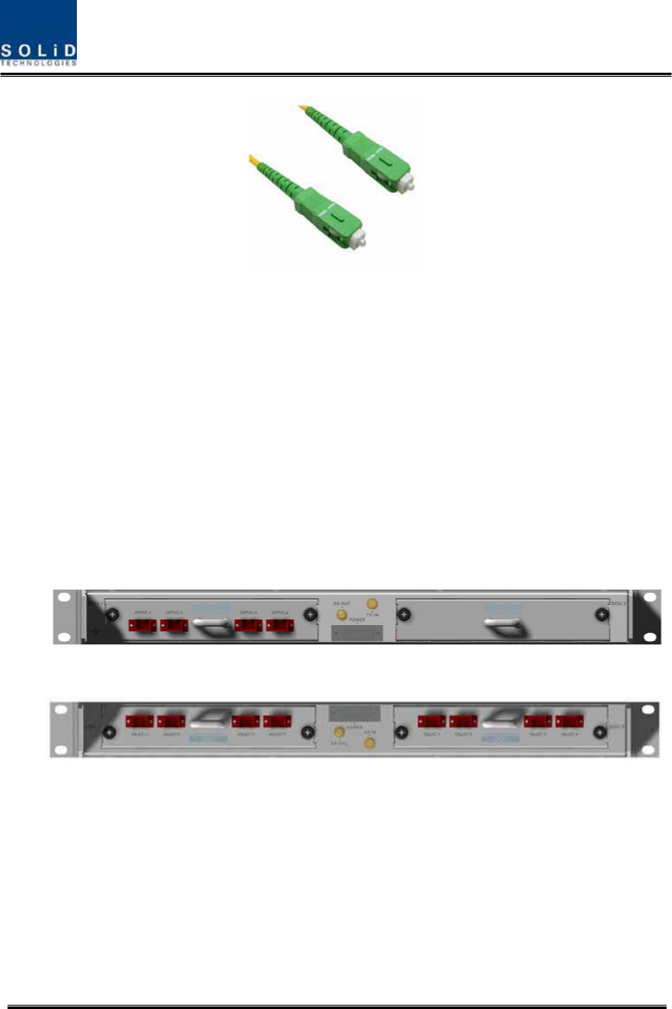
Figure5.27–OpticalcablewithSC/ACPTypeConnectors
SC/APCtypeconnectorsmustbeused.Topreventtheopticalaccesspartfrombeingmarredwith
dirt,itshouldbecoveredwithacapwhennotinstalled.Connectorsshouldbecleanedwithalcohol
beforetheyareinstalled.
Confidential&Proprietary92/122 SC‐DAS
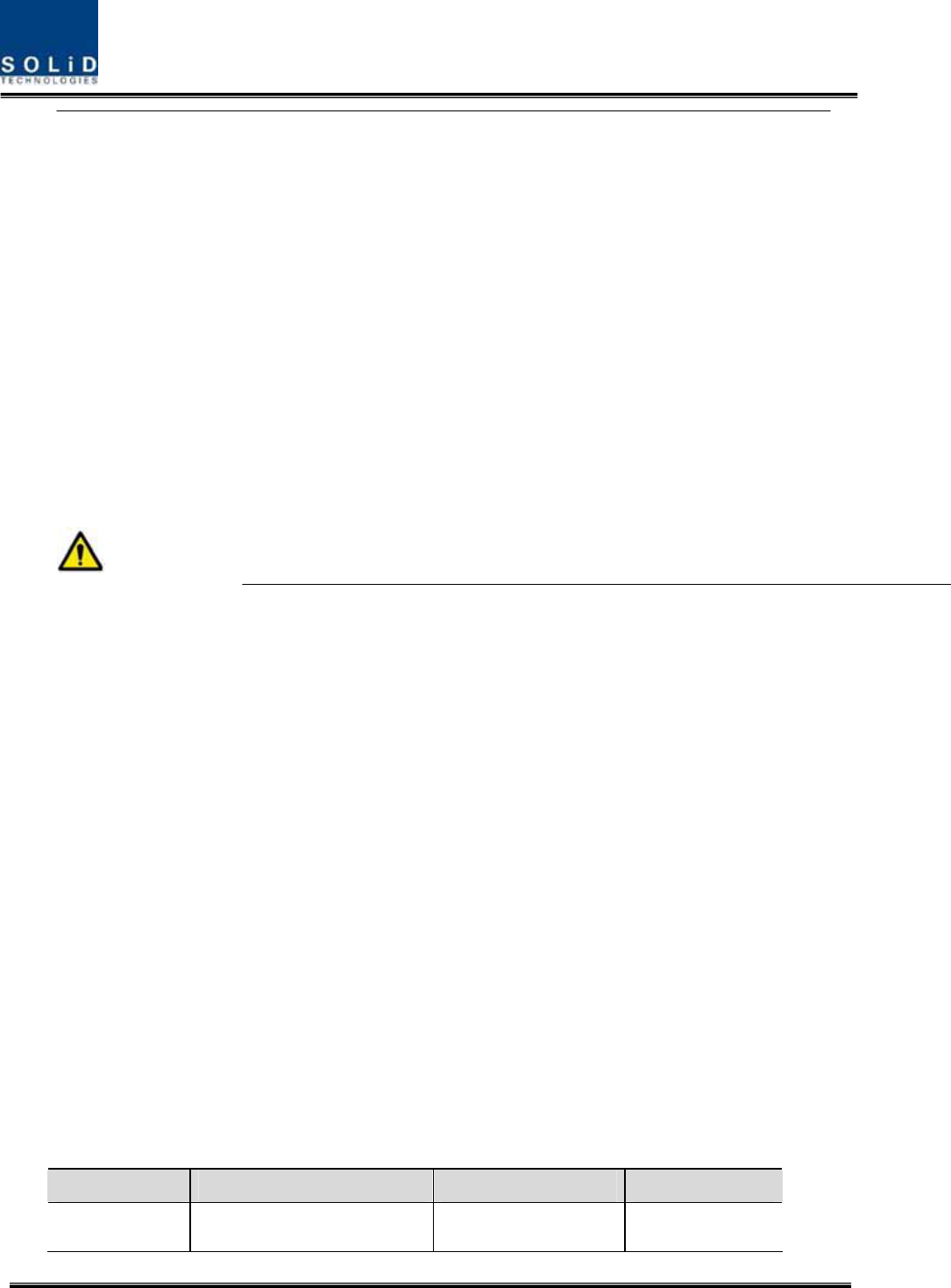
5.4.4 DOUinstallationwithanOEU
UptotwoDOUscanbeinsertedintoanOEUchassis.TheDOUmoduleisaPluginPlaytype.
WhenyouinserttheDOUintotheOEU,insertitintothetopDOU1slotfirst.Slotnumbersare
silkscreenedontheleft.
ThefollowingfigureshowsinstallationdiagramofanOEUwithoneDOUinsertedinit.
ThefollowingfigureshowsinstallationdiagramofanOEUwithtwoDOUsinsertedinit.
Figure5.28–OEUwithDOUsinserted
WhenyouinsertaDOUintoOEU,usetheDOU1slotfirst.Forunusedslots,youneddtoinstall

Confidential&Proprietary93/122 SC‐DAS
BLANKUNITintothem.
5.4.5 OEUPowerConsumption
TheOEUhasa‐48VDCPowersupplyinit.TheOEUcanbeequippedwithuptotwoDOUs.
DependingonthenumberofDOUs,powerconsumptionwillvary.
ThefollowingtableshowspowerconsumptionoftheOEU:
PartUnitConsumptionPowerRemark
Shelf
EWDM
ERF
CommonPart
EPSU
12W
OEU_4DOU1EA23W
OEU_8DOU2EA39W

Confidential&Proprietary94/122 SC‐DAS
Section6
Operation
6.1BIUOperation
6.2ROUOperation
6.3OEUOperation
Confidential&Proprietary95/122 SC‐DAS
ThischapterdescribesoperationofSC‐DAS.Itdealswithproceduresandoperationsfornormal
systemoperationafterinstallation.Italsodescribesoperationsperunitandinterworkingmethods.
6.1 BIUOverview
6.1.1 BIU
Figure6.1–SC‐DASLinkbudgetfortheBIU
6.1.2 BIUTXparameters
TheTXleveltobesenttotheBIUshouldbeintherangeof‐20dBmto+10dBm.Ifthelevelexceeds
therange,youneedtoconnectanattenuatortothefrontendoftheBIUinputandadjustthelevelin
thecorrespondingrange.IfTXinputistoolow,maximumpowercannotbeachievedsoyouneedto
increasetheoutputpowerofBDAoradjustattenuationamountofBTS’scoupleradjustthelevelof
theATT.
Usingaspectrumanalyzer,checkallbandsandverifyiftheyareinanappropriatelevelbefore
makingconnectionwithinputportoftheBIU.Last,checktoseeiftherearespurioussignals.
SelectanMDBUwiththedesiredfrequencybandsand.insertitintotheBIUandchecktoseeifit
worksnormally.FortheMDBU,uptotwoTXinputsareprovided.Inputlevelperportis‐20dBm
to+10dBm.
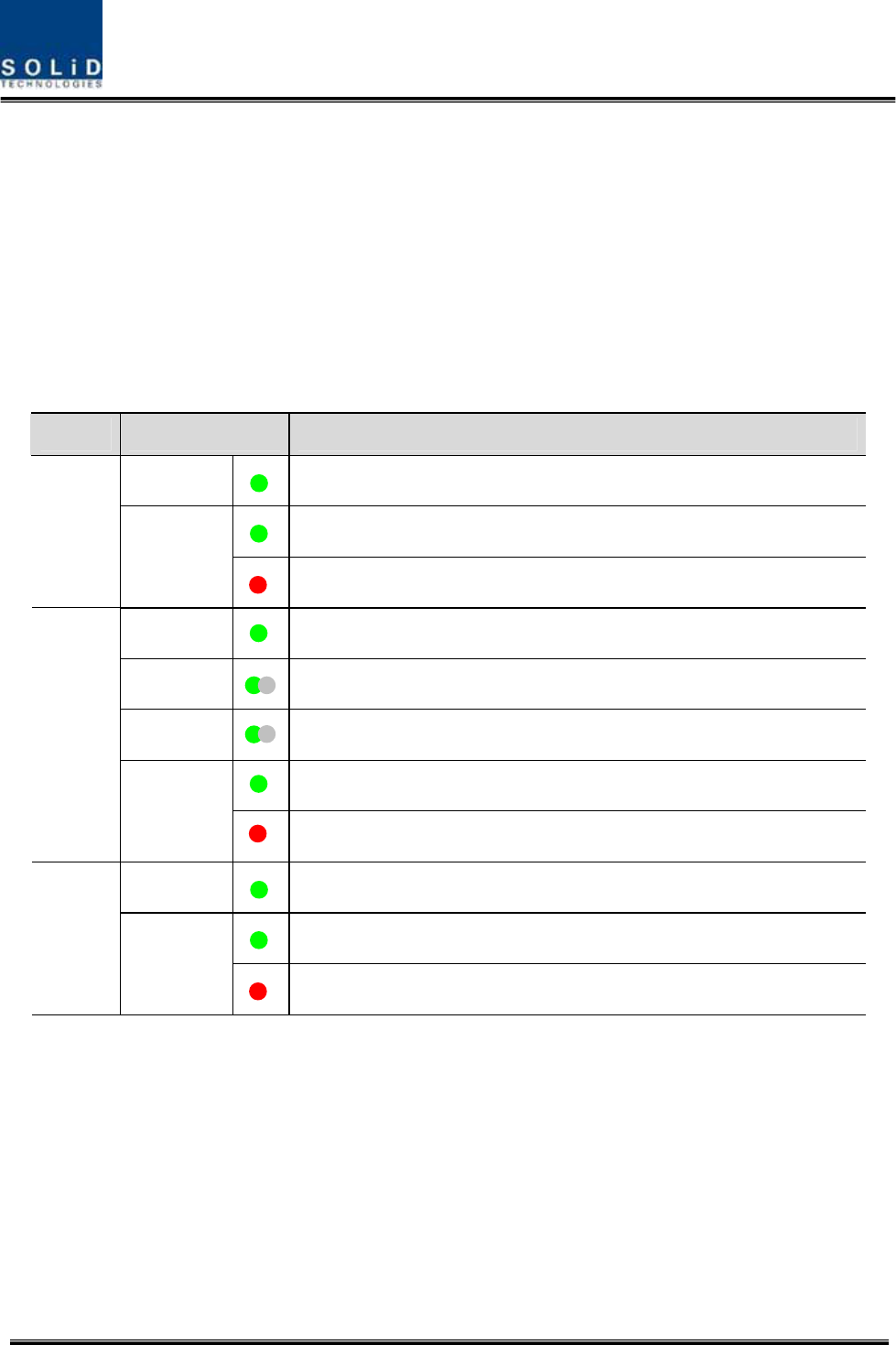
Confidential&Proprietary96/122 SC‐DAS
Checkingthestatusofthesystem’sLEDIndicator
AfterturningontheswitchofthepowersupplyinBIU,checkinformationoneachmodule’s
LEDofthesystem.Thetablebelowshowsnormal/abnormalcasesdependingonthestatus
ofeachmodule’sLED.
LEDinformation
UnitLEDIndicates
ONGreen:MDBUisnormallypower‐supplied.
Green:MDBUisnormal.
MDBU
ALM
Red:MDBUisabnormal;checkthealarmthroughRS‐232C.
ONGreen:MCPUisnormallypower‐supplied.
TXDGreenflicker:TXsignalsaretransmittedtocommunicatewithROU.
RXDGreenflicker:RXsignalsarereceivedfromROU.
Green:BIUsystemisnormal.
MCPU
ALM
Red:BIUsystemisabnormal;checkthealarmthroughRS‐232C.
ONGreen:BIUisconnectedwithpowerandMPSUworksnormally.
Green:DCoutputisnormal.
MPSU
ALM
Red:DCoutputisabnormal.
MDBUSetting
InserttheMDBUintotheBIU.Checkifthe“ON”LEDIndicatoratthefrontpanelofMDBUislit
green.MakeaconnectionwithDEBUGportoftheMCPUthroughUSBCable
CheckiftheIDofMDBUmoduleislocatedinthoseSISOMDBU#1&2,MIMOMDBU#1&2slotsofthe
MDBUthroughtheGUI.Whenyouselectthetabofacorrespondingslotfromthemainwindow,you
caninquireandsetthestatusofacorrespondingMDBUmodule.
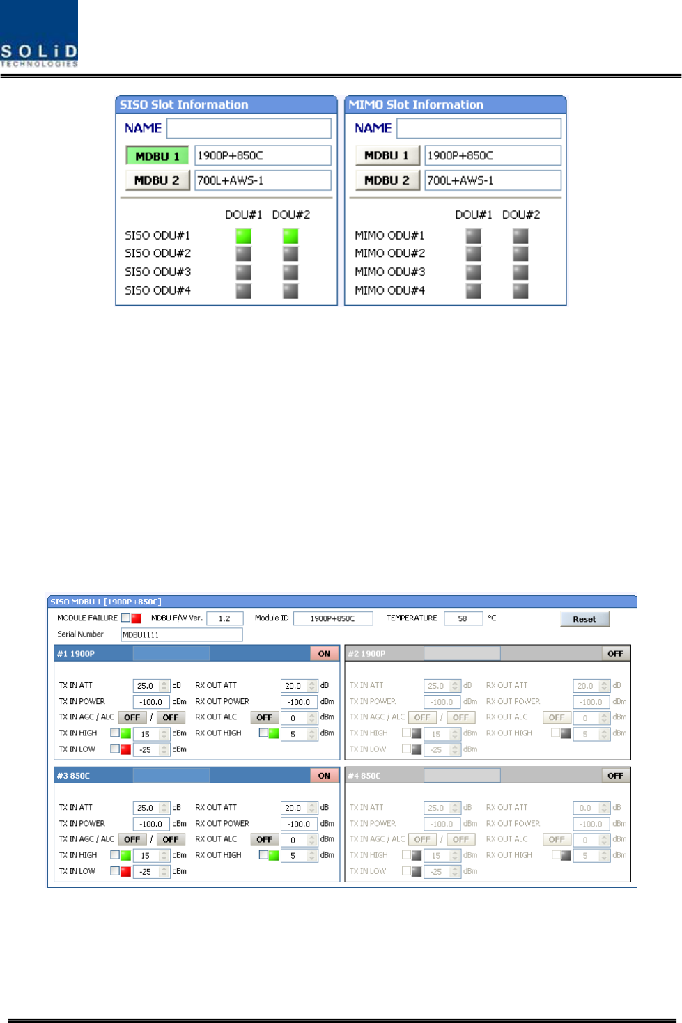
Confidential&Proprietary97/122 SC‐DAS
Figure6.2–MDBUinformationassignedattheBIU
CheckiftheMDBUisinsertedintoacorrespondingslotoftheBIU.TheIDscreenshowsthe
following:
A. MDBUID:ShowMDBUIDinsertedintoslot
B. NotInsert:ThisstatusvalueappearswhenMDBUhasnotbeenset.
C. LinkFail:ThisstatusvalueappearswhenMDBUhasbeensetbutitfailstocommunicate
withmodules.
SC‐DASisclassfiedaccordingtopaththatisasSISOandMIMO.Eachpathcanhaveuptotwo
MDBUs.TheseMDBUscanbedifferentcombinationsasperyourapplication
UsetheON/OFF(Activation/de‐activation)functionforaportyouwanttouseandturnitON.
Figure6.3–MDBUmenuinformationattheBIU

Confidential&Proprietary98/122 SC‐DAS
.MakesuretoturnOFFunusedports.
Thetablebelowshowsoutputpowervsnumberofports
MDBUBandOutputlevel(Compositepower)
No.ofMaxport(N)
700LTE24dBm‐10*LOG(N)2
850Cellular24dBm‐10*LOG(N)2
1900PCS28dBm‐10*LOG(N)2
AWS‐128dBm‐10*LOG(N)2
900I26dBm‐10*LOG(N)2
800I26dBm‐10*LOG(N)2
700PS23dBm‐10*LOG(N)2
VHF24dBm‐10*LOG(N)1
On the loadmap

Confidential&Proprietary99/122 SC‐DAS
UHF24dBm‐10*LOG(N)1
CheckifthelevelofTXINPOWERisthesameasthevaluemeasuredwithspectrumanalyzer(Within
±3dB).UseTXINAGCfunctionandautomaticallysetinternalATTdependingoninputlevel.ATTis
automaticallysetbasedon‐20dBmofinput.ThetablebelowshowsTXINATTdependingonTXIN
POWER.Formanualsetting,youcansetATTdependingoninputaccordingtothetable.
TXINPOWERTXINATTTXINPOWERTXINATTTXINPOWERTXINATT
‐20dBm0dB ‐9dBm11dB+1dBm21dB
‐19dBm1dB ‐8dBm12dB+2dBm22dB
‐18dBm2dB ‐7dBm13dB+3dBm23dB
‐17dBm3dB ‐6dBm14dB+4dBm24dB
‐16dBm4dB ‐5dBm15dB+5dBm25dB
‐15dBm5dB ‐4dBm16dB+6dBm26dB
‐14dBm6dB ‐3dBm17dB+7dBm27dB
‐13dBm7dB ‐2dBm18dB+8dBm28dB
‐12dBm8dB ‐1dBm19dB+9dBm29dB
‐11dBm9dB0dBm20dB+10dBm30dB
‐10dBm10dB
TheMDBUcardsintheBIUprovideALC(AutoLevelControl)functionalityforeachoftheinputsto
limitthemaximumpoweroutputpercarrierinput.TheinputlevelstartsactivatingALCat‐20dBm
whenturningtheALCon.Forcorrectparametersettings,first,performtheinputAGCandthen
turntheALCfunctionon.
Edittheportnameandsetitasadesiredcharacterstring(upto12characters).Forexample,the
figurebelowshowsascreenwhenyouset“VzW”forport1and“AT&T”forport2.
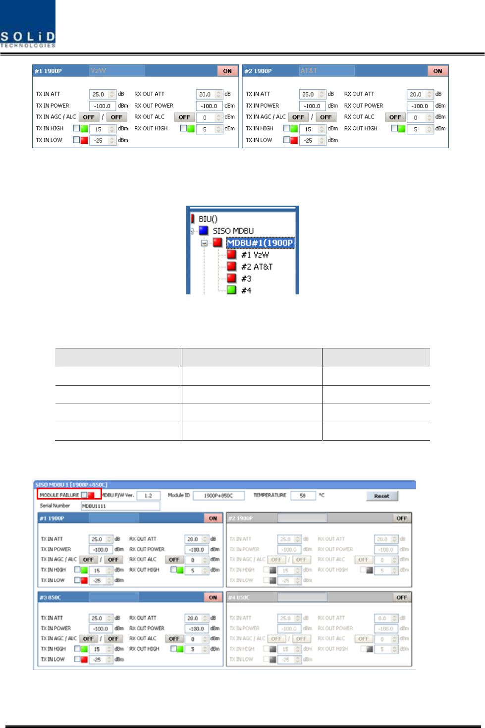
Confidential&Proprietary100/122 SC‐DAS
Figure6.4–MDBUnameassignmentattheBIU
Thisnamingisreflectedatthetreeasfollows
Figure6.5–MDBUnameassignmentatthetree
Usevariousupper/lowerlimits.Thefollowingtableshowsrecommendedlimitsettings:
ItemRecommendedLimitRemark
TXINHIGHALM15dBmAlarm
TXINLOWALM‐25dBmAlarm
RXOUTALC0dBmAutoLevelcontrol
RXOUTHIGHALM5dBmAlarm
Afteryoufinishsettingnormalinputlevelsandalarmlimits,checktoseeiftheMODULEFAILURE
LEDIndicatorislitgreen(Normalcase).
Figure6.6–MDBUModuleFailureinformationattheBIU

Confidential&Proprietary101/122 SC‐DAS
6.1.3 BIURXparameters
ForRXoperationatBIU,youneedtosetRXgaintopreventtheBTSorBDAfrombeing
affected.ThereisanATTsettingwindowtoletyouadjustgainperbandandport.
TotalRXgainis50dBperband.Toadjustadesiredgain,youneedtodothefollowing.Fora
desiredRXgain,youcansetitas50dB‐RXATT.UsetheterminalandcheckifTXAdjustvalue
andEc/Iovalueisappropriate.
TopreventhighlevelsignalsfromenteringtheBTSorBDA,keepALCmodeactivated(ON).
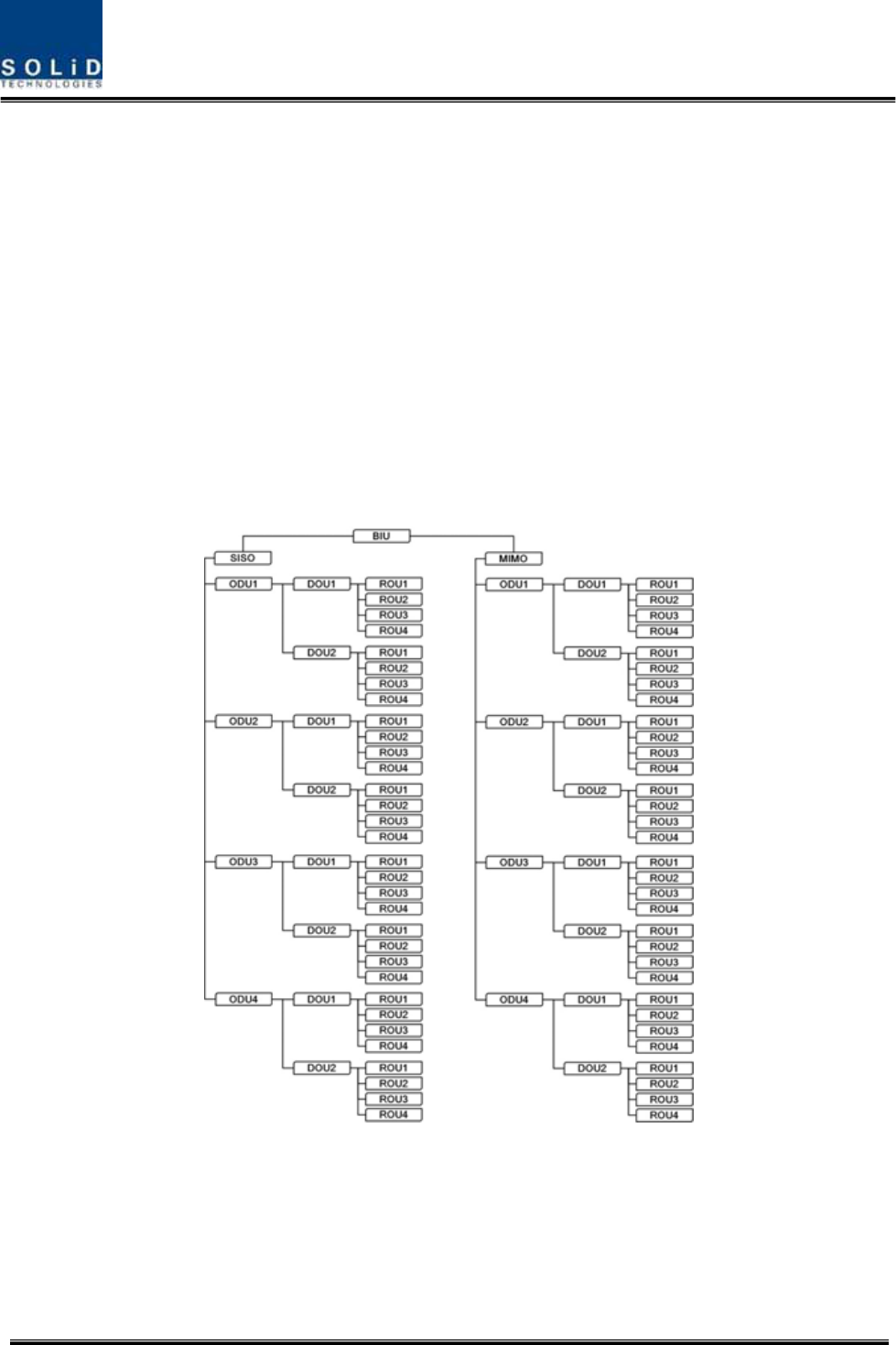
Confidential&Proprietary102/122 SC‐DAS
6.1.4 BIULogicSequenceDiagram
TheBIUcontrolstheoverallsystem,workingasastheheadendunitofanysystem.TheBIU
connectswithunitssuchasODU,OEUandROU.
Thetreehierarchyautomaticallydisplaysthecomponentsconnectedtothesystemand
communicatewithlowerunitswhilecollectingthestatusoftheunits.
Themenubelowshowstopologyforoverallunits.
BasictopologyforSC‐DAS
ConfigurationofBIU‐ODU‐ROU
Figure6.7–ConfigurationofBIU‐ODU‐ROUforbasictopology
TheBIUhastwopaths:SISOandMIMO.Eachpathhascapabilitytoconnectupto4ODUs,
oneODUcanbeconnectedupto8ROUs.Therefore,thenumberofROUsperpathis32.
RegardingtheMIMOpath,OneBIUcanconnectupto64ROUs
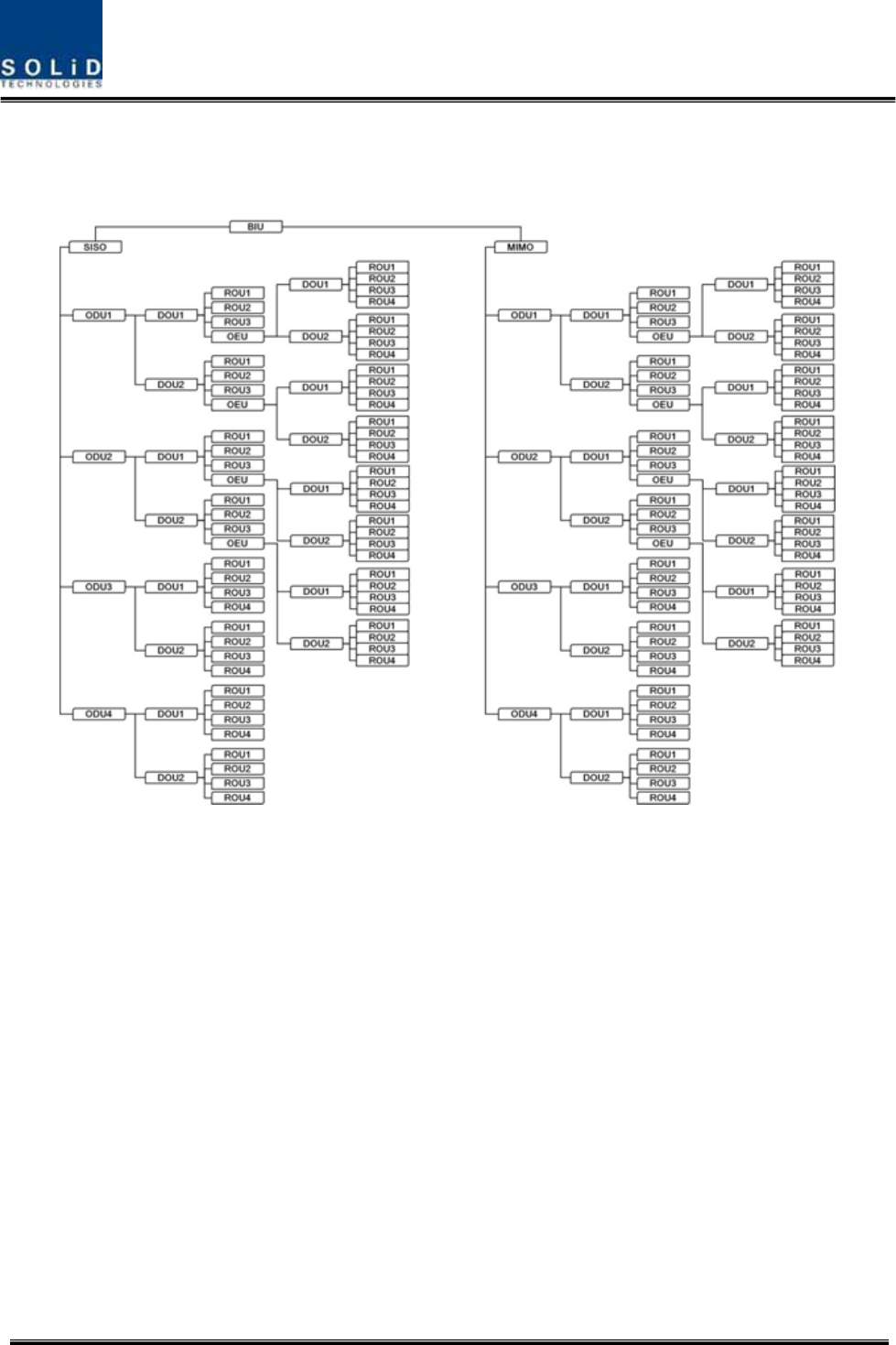
Confidential&Proprietary103/122 SC‐DAS
ExpansiontopologyforSC‐DAS
ConfigurationofBIU‐ODU‐OEU‐ROU
Figure6.8–ConfigurationofBIU‐ODU‐ROUforexpansiontopology
UsinganOEUallowsyoutoexpandforadditionalROUsasshowninthetreestructures.
Lookingattheabovetreehierarchy,anOEUcanbeconnectedwithODU1and2onlyand
regardingtheopticalportofaDOU,theOEUcanonlyconnecttothefourthopticalport.If
youtrytoconnecttheOEUports1thru3oftheDOU,theBIUwon’tcommunicatewithit.
ThistreehierarchyisgeneratedautomaticallyastheROU/OEUisconnectedattheODU
opticalport
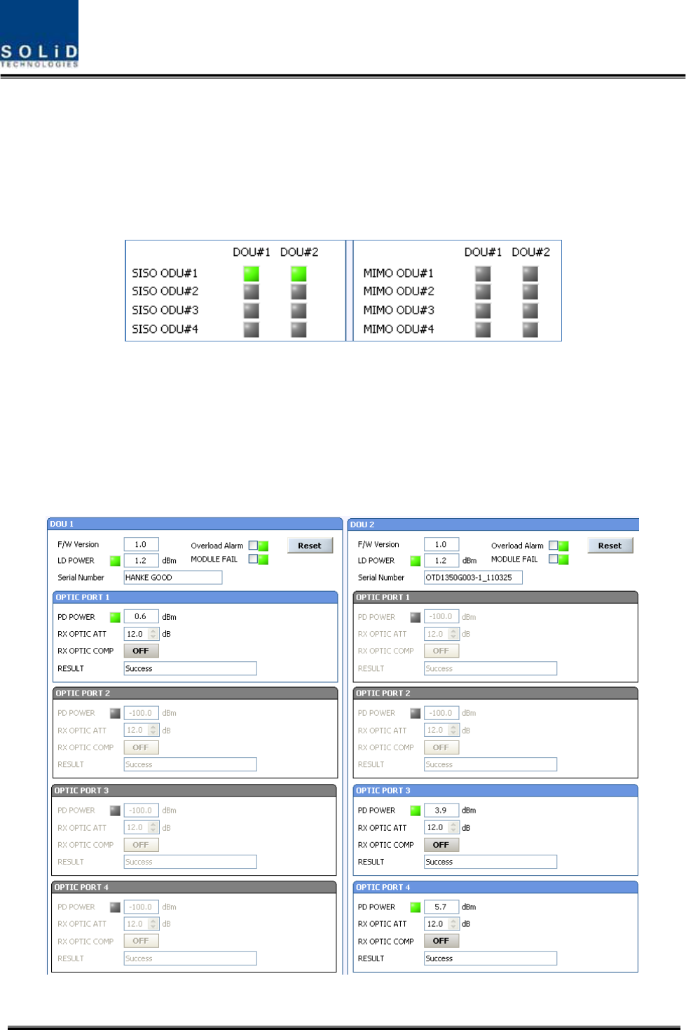
Confidential&Proprietary104/122 SC‐DAS
6.1.5 InteractionwiththeBIU
TheBIUcanbeequippedwithuptofourODUsperpath.OneODUcanhavetwoDOUsinit.For
informationoninsertion/deletionoftheDOUintheODU,lookatthemainwindowoftheBIUas
shownbelow
Figure6.9–DOUassignmentattheBIU
WhenyouselecttheODUscreenfromtheleftTREEpanel,youcanseetheDOU1orDOU2menu
actiavteddependingonwhetherDOUhasbeeninserted.Then,theopticalportsetattheINSTALL
menuisalsoactiavtedtoletyoucheckPDvalueoftheopticalport.Anyunusedopticalportisseen
de‐activatedingrey.
Figure6.10–ODUMenuinformation
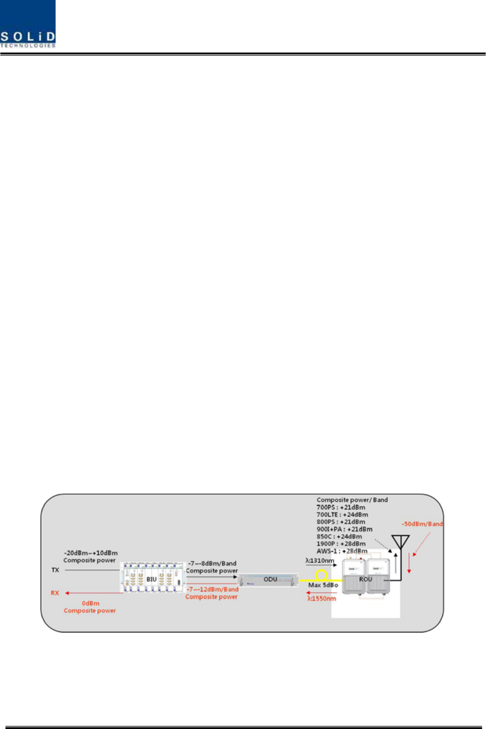
Confidential&Proprietary105/122 SC‐DAS
ThelevelofDOU’sLaserdidoeistypically+1.5±1dBm.DOUshavevariousalarmsuchasLDPower
alarm,OverloadAlarmandPDalarms.
ThelevelofLaserdiodereceivedfromROU/OEUis+7dBm±0.5dB.ThelevelofPhotodiodewillbe
displayedwithlossesrelatedtothelengthofopticalcablesandinsertionlossofopticalconnectors.
Ingeneral,thelevelofopticalPDPOWERshouldbe+6dBmto+2dBm±1.5dB.
Furthermore,theODUhasthefunctionofautomaticallycompensatingforopticalcableloss.
Initially,ifBIUcommunicateswiththelowerUnit(OEU,ROU),theopticallosscompensationis
automaticallyaffected.
Duringopticalcompensation,theResultwindowshows"Processing"andthenaresultvalue.There
arethreetypesofresultsasfollows:
A. Success:Theopticalcompensationisnormallycompleted
B. OverOpticLoss:Generatedopticallossis5dBoormore.
C. CommunicationFail:CommunicationwithROUisinpoorconditin.
TheATTforopticalcompensationcanworkbasedonthenumericalexpressionof12‐2*(LD
POWER‐PDPOWER).OpticalcompensationcanbemadenotonlyintheODUbutalsointheROU.
6.2 ROUOverview
ThefigurebelowshowstheSC‐DASsystemlinklevel(BIU‐ODU‐ROU).ThissectiondescribesROU‐
relatedinformation.TheROUreceivesvarioussignalsthroughopticalmodules.Thesesignalsare
filteredonlyforcorrespondingsignalbandfromtheMFR/ARFmoduleandamplifiedwithaHigh
PowerAmplifier.Then,themultiplexercombinesthesignalswithothersandsendsthemtothe
antennaport.
Figure6.11–SC‐DASLinkbudgetforROU

Confidential&Proprietary106/122 SC‐DAS
6.2.1 ROUOperation
TheROUisaone‐bodyenclosuretypeandislocatedataremoteclosetinthebuilding.It
canbeinstalledonawallorintoarack.
Basically,onlyoneantennaportisprovided.Toinstallmultipleantennas,youneeddividers
and/orcouplers.TheROUcanworkwithaDCFeederandanOpticCableFeeder.Topower
theROU,apowersupplyofeitherAC‐DCorDC‐DCcanbeselecteddependingonthe
application.
Forupperlevel,theROUcanbeconnectedwiththeODUandOEU.IthasanAGCfunction
for5dBoofopticalcableloss.
ThefollowingshowsoperationalproceduresafterinstallationoftheROU.
CheckingthestatusofROU'sLEDIndicator
Whenpowercableispluggedintoanoutlet,powerisprovidedfortheROU.Check
informationoneachmodule'sLEDofthesystem.Thetablebelowshowsnormal/abnormal
casesdependingonthestatusofeachmodule'sLED.
CheckingCommunicationLEDofROU
CheckifTXDandRXDLEDsintheMRUmakecommunication.ReceivingFSKsignalsfromtheBIU,
LEDDescription
Powerisnotsupplied
ON
Powerissupplied.
NormalOperation
ALM
AbnormalOperation
R‐OPTisnormaloperation
OPT
R‐OPTisabnormalOperation
TXDFlashingwhendatasendtoupperunit
RXDFlashingwhendatareceivefromupperunit

Confidential&Proprietary107/122 SC‐DAS
theROUsendsrequestedstatusvaluetotheBIU.Duringreception,RXDLEDblinks.During
tramsmission,,TXDLEDblinks.Atthistime,youneedtoseeifwhethertouseacorrespondingROU
ischeckedon
WhentheARUisconnectedwiththeMRU,checkifTXDandRXDLEDsatARUblink.Atthistime,
checkwhetherexternalcableisconnectedtotheMRUandARU
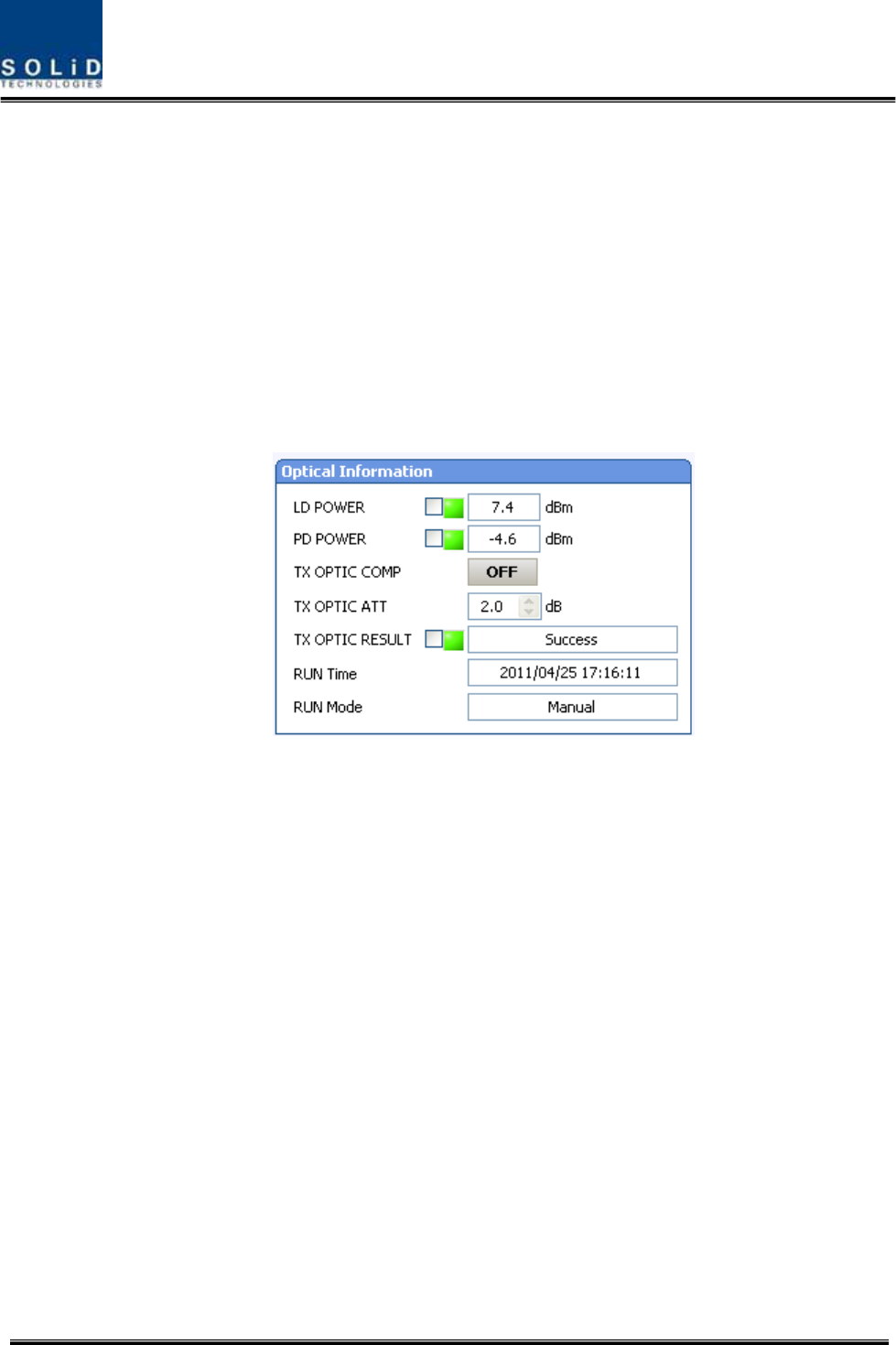
Confidential&Proprietary108/122 SC‐DAS
ROUOpticCompOperation
TheROUhasthefunctionofautomaticallycompensatingforopticalloss.Itcandotheworkforupto
5dBoofopticalloss.Set“TXOPTICCOMP”oftheMRUto"ON."OpticalcompensationofROUcan
notbemadewithoutcommunicationtotheODUorOEU.For1dBoofopticalloss,basicTXOPTIC
ATTis1dB;for5dBoofopticalloss,TXOPTICATTis4dB.OPTICCOMPworksonlyonetimebeforeit
staysdormant.
ThefigurebelowshowsascreenforOPTICInformationinROUGUI.
LDPOWERreferencestheoutputlevelofROULaserDiodewhichissenttoaupperunitbytheROU.
PDPOWERreferencestheinputlevelofPhotoDiodetobereceivedfromaupperunit.
Figure6.12–OpticalinformationattheROU
Initially,WhentheROUcommunicateswiththeupperdevice(ODU/OEU),opticallosscompensation
isdoneautomatically.Duringopticallosscompensation,theresultwindowshows"Processing"and
thenaresultvalueisdisplayed.Therearethreetypesofresultsasfollows:
1. Success:Theopticalcompensationisnormallycompleted.
2. OverOpticLoss:Generatedopticallossis5dBoormore.
3. CommunicationFail:CommunicationwithROUisinpoorcondition.
ContinueifTXopticresultissuccessful.Iftheresultsare“overopticLoss”,cleanopticalconnector
faceusingclearcloth,andthenoperateTXOPTICCOMPagain.
Also,youcanperformopticallosscompensationmanually.Here,RUNModedisplaystwotypesas
shownbelow
1. Auto:CPUofMRUisperformedautomaticallywheniscommnincatedwithupperdevice
2. Manual:whenuserperformsmanually.Thisresultwilldisplay

Confidential&Proprietary109/122 SC‐DAS
IfROUdoesnotmakeopticalcompensation,therewillbeerorsinthesystemlinkbudget.It
cancauseloweroutputlevelsormakeSpuriousEmissionsdetrimentaltothesystem.
ROUSetting
TheMRUcanbeinterfacedwithtwoRUs.OneisanARUwhichisprovidedwithanextracarrier
band.TheotherisaVHF+UHFRUwhichisprovidedwithpublicsafetyservicerequiredinthebuilding
code.
ThroughtheGUIattheMRU,itqueriesthestatusandcontroloftheMRU,theARUandthe
VHF+UHFRU
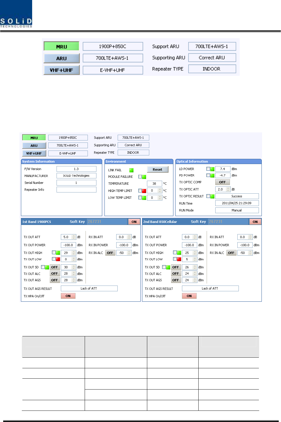
Confidential&Proprietary110/122 SC‐DAS
Figure6.13–ROUinformationassignment
ByclickingthemainmenuwhichisMRU,ARUandVHF+UHF,youcanqueryandcontroltheseunits
SetHPAofacorrespondingRDUas“ON.”UseTXOUTPUTAGSfunctionandsetitasadesired
outputlevel.
Figure6.14–ROUMenuinformation
ThetablebelowshowsmaximallyallowableCompositePowerlevelsthatcanbesetperband:
RDUBandPowerthatcanbe
maximallyset
SettingrangeRemark
700LTE24dBm0~24dBmARU700LTE+AWS‐1
850Cellular24dBm0~24dBmMRU1900PCS+850C
28dBm0~28dBmMRU1900PCS+850C
1900PCS
31dBm0~28dBmMRU1900PCS
AWS‐128dBm0~28dBmARU700LTE+AWS‐1
Confidential&Proprietary111/122 SC‐DAS
900I26dBm0~26dBmARU900I+800I
800I26dBm0~26dBmARU900I+800I
AGSfunctionenablesyoutoadjustoutputpowerasyoulike.WhiletheAGSfunctionisbeing
executed,theResultwindowshows"Processing"andthenaresultvalueisdisplayed.Therearethree
typesofresultsasfollows:
A. Success:TheAGSfunctionisnormallycompleted.
B. NotOpterateOPTICComp:OpticCompisnotexecuted.
C. LackofATT:Thereisnoattenuationavailable.
Settheupper/lowerlimits.Thefollowingtableshowsrecommendedlimitsettings:
ItemRecommendedLimitRemark
TXOUTPUTHIGHALMMaxCompositePower+1dBAlarm
TXOUTPUTLOWALM0dBmAlarm
TXOUTPUTALCMaxCompositePowerAutoLevelcontrol
TXOUTPUTSDMaxCompositePower+2dBShutdown
RXALC‐45dBm
IfTXOUTPUTHIGHALMishigherthanasettingvalue,alarmswillbegenerated.
IfTXOUTPUTLOWALMislowerthanasettingvalue,alarmswillbegenerated.TXOUTPUTHIGH
ALM/LOWALMtendstoworkonlyaswarning.
Whenyouactivate(“ON”)TXOUTPUTALC,outputswillberestricteddependingonasettingoutput
value.
Whenyouactivate(“ON”)TXOUTPUTSD,outputwillbeturnedOFFonceoutputpowerlevel
reachesthesameasSDsettingvalue.UponSDoperation,checkoutputlevelafter10minutesand
thencheckthestatusagain.
Whenyouactivate(“ON”)RXALC,inputswillberestricteddependingonasettingvalue.
Asdescribedabove,whennormaloutputlevelandalarmlimitvaluesareset,youneedtocheckif
thevalueofMODULEFAILURELEDIndicatorisgreen.
Forunusedbands,youneedtousebandselect‐ON/‐OFFfunctiontoturnthemoff.
TheROUhassoftkeyfunction,whensoftkeyisidentifiedwithserialnumber,thebandcanbe
activated.
Ifthesoftkeydonotidentifywiththeserialnumber,youcannotusethatband.Thesoftkeyhasa
uniquevalueaccordingtoserialnumber.Tousetwobandssimulatanously,youshouldentersoftkey
value.
Figure6.15–ROUSoftkeyinformation

Confidential&Proprietary112/122 SC‐DAS
,TheROUhasuniqueserialnumberandalsoauniquesoftkey.
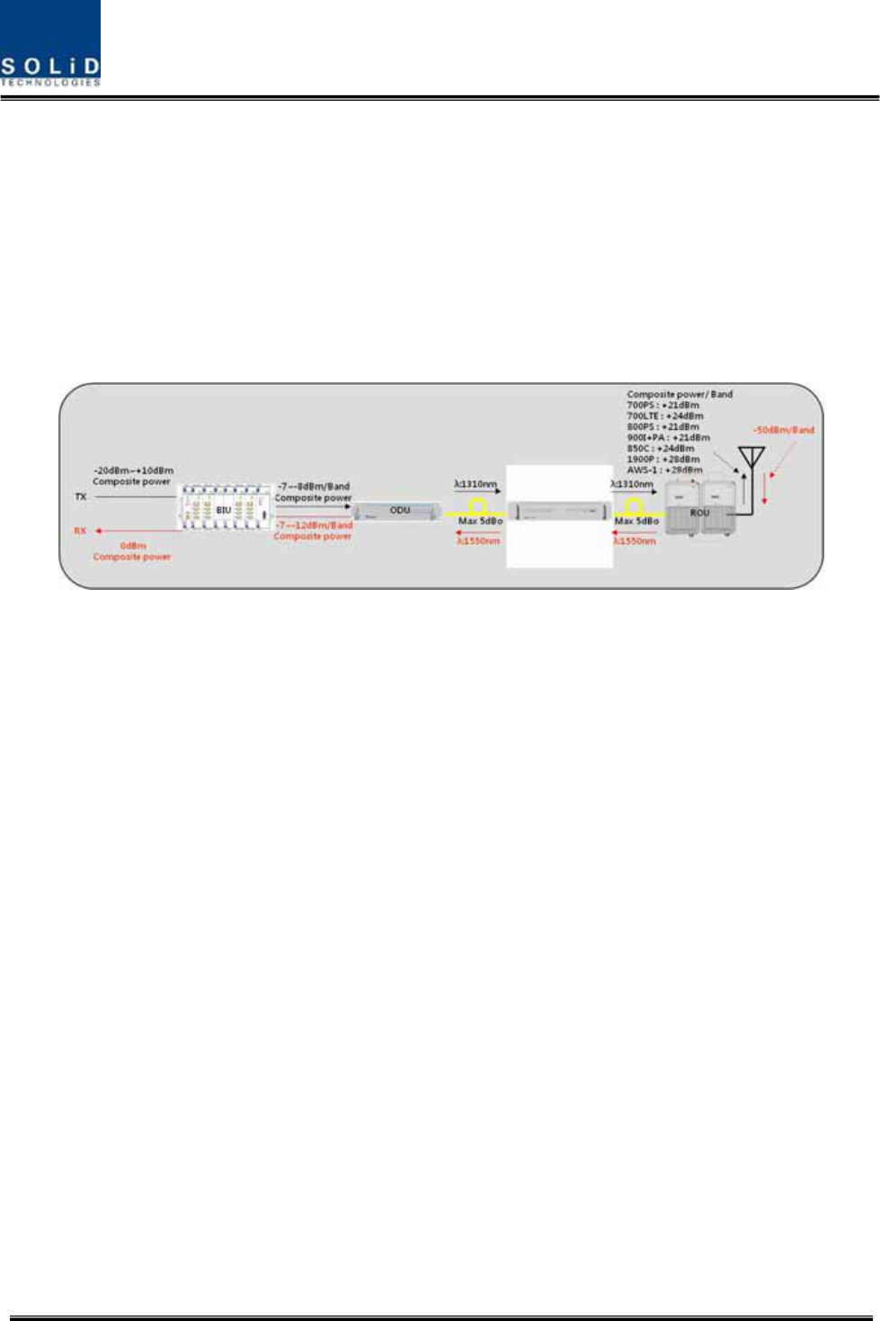
Confidential&Proprietary113/122 SC‐DAS
6.3 OEUOperation
ThefigurebelowshowsthesystemlinklevelofSC‐DAS(BIU‐ODU‐OEU‐ROU).Thissectiondescribes
OEU‐relatedinformation.TheOEUreceivesvarioussignalsthroughopticalmodules.Theoptical
signalsareconvertedtoRFsignalsandtheRFsignalareamplifiedtomoderatesignallevels.To
transmittoROU,thesignalisconvertedtoanopticalsignal
Figure6.16–SC‐DASLinkBudgetforOEU
6.3.1 OEUOperation
TheOEUcomesasarackmountchassisandislocatedataremoteclosetinabuilding.
TheOEUsmainfunctionistoactasahubforexpansiontootherbuildings,Itonlyrequires
onestrandoffibertoexpandto8ROUs.(OEUsupportsupto2DOUsandtheDOU
supportsupto4opticalportsthatconnectROUs).
TheROUcanworkwithaDCFeederandanOpticCableFeeder.oftheOEUrequiresaDC‐
DCpowersupply.
Intheotherdirection,theOEUcanbeconnectedwithaODU.Ithasopticalloss
compensationfunctionfor5dBoofopticalcableloss.Thefollowingshowsoperational
proceduresafterinstallationoftheOEU.
CheckingthestatusofOEU'sLEDIndicator
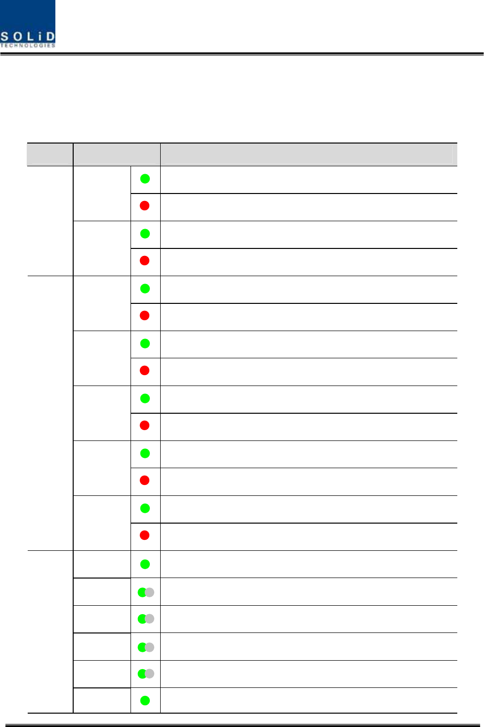
Confidential&Proprietary114/122 SC‐DAS
AfterturningontheswitchofthepowersupplyintheOEU,checkinformationoneach
module'sLEDofthesystem.Thetablebelowshowsnormal/abnormalcasesdependingon
thestatusofeachmodule'sLED.
UnitLEDIndicates
Green:LaserDiodenormalstatus
LD
Red:LaserDiodeabnormalstatus
Green:PhotoDiodenormalstatus
EWDM
PD
Red:PhotoDiodeabnormalstatus,inputopticpowerlowalarm
Green:LaserDiodenormalstatus
LD
Red:LaserDiodeabnormalstatus
Green:PhotoDiode(PD)ofopticport1isnormal
PD1
Red:PDofopticport1isabnormalorinputopticpowerlow
Green:PhotoDiode(PD)ofopticport2isnormal
PD2
Red:PDofopticport2isabnormalorinputopticpowerlow
Green:PhotoDiode(PD)ofopticport3isnormal
PD3
Red:PDofopticport3isabnormalorinputopticpowerlow
Green:PhotoDiode(PD)ofopticport4isnormal
DOU1,2
PD4
Red:PDofopticport4isabnormalorinputopticpowerlow
ONGreen:Poweron
TXD1Greenflicker:ECPUsendNMSTxdatatoBIU
RXD1Greenflicker:ECPUreceiveNMSRxdatafromBIU
TXD2Greenflicker:ECPUsendNMSTxdatatoROU
RXD2Greenflicker:ECPUreceiveNMSRxdatafromROU
System
ALMGreen:OEUsystemnormal(noalarm)
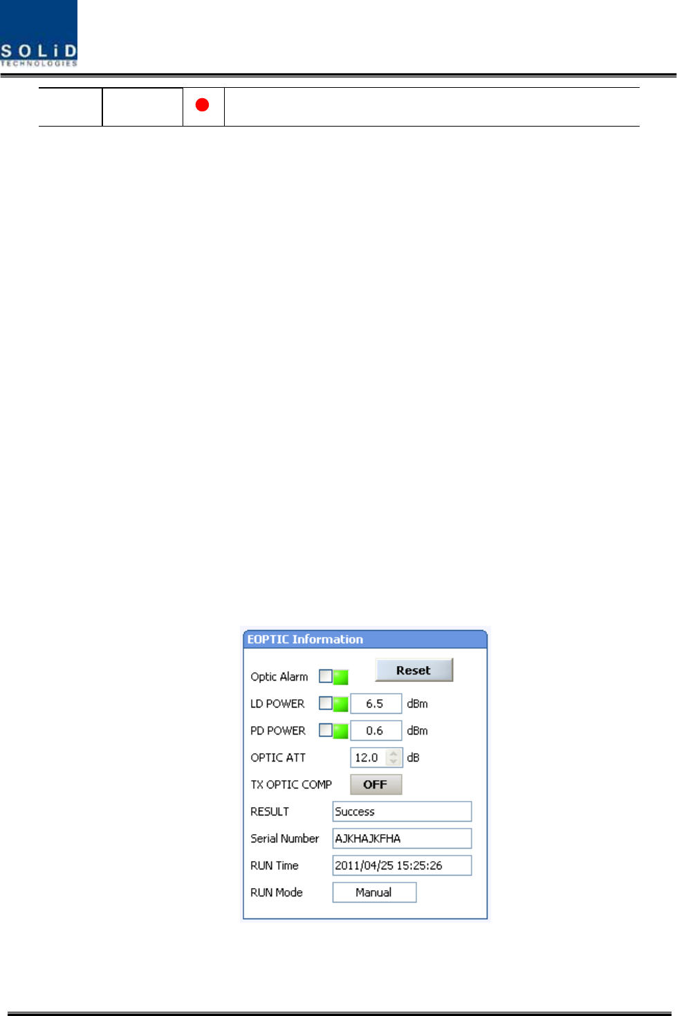
Confidential&Proprietary115/122 SC‐DAS
Red:OEUsystemabnormal(alarm)
CheckingCommunicationLEDofOEU
Step1:checkingwhetherthereiscommunicationwiththeBIU(ODU)
CheckifTXD1andRXD2LEDsinOEUfrontLEDmakecommunication.ReceivingFSKsignalsfromBIU,
theOEUsendsrequestedstatusvaluetoBIU.Duringreception,RXD1LEDflicks.During
tramsmissionTXD1LEDflicks.
Step2:CheckingwhetherthereiscommunicationwiththeROU
OEUconfiguredasaHub.OEUhastwoopticalports.OneisconnectedtoupperODUandtheothers
isconnectedtoROU.CommunicationwithODUwascheckedatabovestep1
Step3ischeckingwhethertheOEUcommunicateswiththeROU.TheOEUrequeststatustothe
ROUandthenTXD2blinksIfresponesdataisreceivedfromROU,RXD2LEDblinks
OEUOpticCompOperation
TheOEUhasthefunctionofautomaticallycompensatingforopticalcalbeloss.Itcandotheworkfor
upto5dBoofopticalloss.Set“TXOPTICCOMP”ofOEU’sopticas"ON."Opticalcompensationof
theOEUcannotbemadewithoutcommunicationwiththeODU.For1dBoofopticalloss,TXOPTIC
ATTis1dB;for5dBoofopticalloss,TXOPTICATTis4dB.OPTICCOMPworksonlyonetimebeforeit
staysdormant.
ThefigurebelowshowsascreenforOPTICInformationintheOEUGUI.
LDPOWERreferencestheoutputlevelofOEULaserDiode,whichissenttoaupperunitbytheOEU.
PDPOWERreferencestheinputlevelofPhotoDiodetobereceivedfromaupperunit.
Figure6.17–OEUOpticalinformation

Confidential&Proprietary116/122 SC‐DAS
NormalLDpowerlevelistypically+7dBm±1dBm,PDpowerisrangeof+1dBmto‐5dBm.Theresults
valueissametotheROU’sopticallosscompensation(seetheROUmoredetail)
LiketheROU,theOEUperformsopticallosscompensationautomaticallywhentheOEU
communicateswithupperODUfirst.
Duringopticalcompensation,theResultwindowshows"Processing"andthenaresultvalueis
displayed.Therearethreetypesofresultsasfollows:
1. Success:Theopticalcompensationisnormallymade.
2. OverOpticLoss:Generatedopticallossis5dBoormore.
3. CommunicationFail:CommunicationwithROUisinpoorconditin.
TheOEUcanbeinsertedwithtwoDOUs.TheDOU’sbehaviorisexactlysametotheODU(Seethe
ODUformoredetail)
IfOEUdoesnotmakeopticalcompensation,therewillbeerrorsinthesystemlinkbudget.It
cancauselowoutputlevelsormakeSpuriousEmissionsdetrimentaltothesystem.

Confidential&Proprietary117/122 SC‐DAS

Confidential&Proprietary118/122 SC‐DAS
Section7
Additivefunctions
7.1Shutdownfunction
7.2Totalpowerlimitfunction
7.3AutomaticOutputpowersettingfunction
7.4InputpowerAGCfunction
7.5Inputpowerlimitfunction
7.6Opticlosscompensation
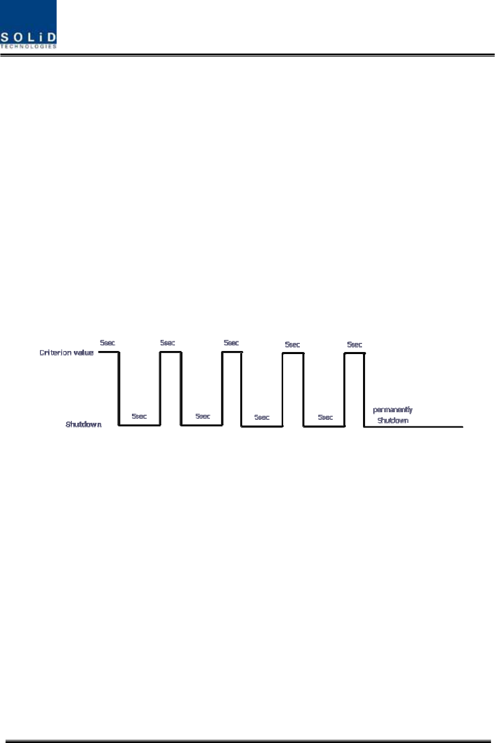
Confidential&Proprietary119/122 SC‐DAS
ThischapterdescribesadditivefunctionsofSC‐DAS
7.1 Shutdownfunction(TXoutputshutdown)
TheDAShasanautomaticshutdownfunctiontoprotecttheDASitselfandthewireless
networkwhenthenormaloperationalconditionscannotbemaintained
Shutdownistriggeredautomaticallywhenthecompositepowerdownlinkoutputisabove
thevaluesdefinedasaverageforthedeviceforaperiodnottoexceed5seconds.Critical
levelsaresetthroughtheGUI
Afterautomaticshutdown,thesystemmayautomaticallyturn‐oninordertoassess
whetherthetemporaryconditionhaschanged.Iftheconditionisstilldetected,theDAS
shallshutdownagain.Thisactionwillberepeated5times
AfterThe5thtime,iftheconditionisstilldetected,theDASwillbeshutdownpermanently.
Thefollowingdiagramshowstheshutdownlogic
Figure7.1–Shutdownlogicdiagram
Aftertheretrylogicexhaustsitself,theDASwillshutdownpermanentlyandilluminatethe
faultviavisualfaultindicator
PermanentshutdownsoftheDASwillalsobereportedtotheNOCthroughtheNMS
7.2 TotalPowerLimitfunction(TXOutputALC)
InordertoprotecttheHPAandnottoradiatespuriousemissions,outputpowersislimited
toadefinedvaluewhichissetbytheoperatorinadvance.Toexecutethisfunction,
operatorshouldturn‐ontheALCfunctionandsetlimitlevelthroughtheGUI.Iftheoutput
powerexceedsthedefinedvalue,theoutputattenuatorisadjustedtoreturnitwithin
definedvalue.Theoutputattenuator’sadjustmentrangeis25dBmax.Ifoutputpower
decreases,attenuationisdecreasedusingtheAGCfunctiontoreturntotheinitial
attenuationlevel.

Confidential&Proprietary120/122 SC‐DAS
7.3 AutomaticOutputpowersettingfunction(TXOutputAGC)
Toprovideconvenienceofsettingoutputpoweratinitialsetupautomatically,setoutputto
desiredlevelandturn‐ontheAGCfunction.Theoutputpowerisautomaticallysetto
definedlevel.
AfterAGClogiciscomplete,logicoperationresultswillshowontheresultwindowofthe
GUI.Therearethreetypesofresultsasfollows
1. Success:TheAGSfunctionisnormallycompleted.
2. NotOpterateOPTICComp:OpticCompisnotexecuted.
3. LackofATT:Thereisnoattenuationavailable.
Ifnormallogiccan’tbeexecuted,changedATTwillreturntoinitialATT
ThroughtheoutputAGCfunction,itcanbeverifiedwhetheropticcompensationis
executedornot.
7.4 InputpowerAGCfunction(TXInputAGC)
Thisfunctionistohelptheoperatorwithinitialsettingduringinstallation.
Withoutaspectrumanalyzer,wecanseetheinputpowervaluethroughpowerdisplay
windowoftheGUI.UsetheTXINAGCfunctionandautomaticallysettheinternalATT
dependingontheinputlevel.TheATTisautomaticallysetbasedon‐20dBminput.The
tablebelowshowsTXINATTdependingonTXINPOWER.Formanualsetting,youcanset
ATTdependingoninputaccordingtothetable.
TXINPOWERTXINATTTXINPOWERTXINATTTXINPOWERTXINATT
‐20dBm0dB ‐9dBm11dB+1dBm21dB
‐19dBm1dB ‐8dBm12dB+2dBm22dB
‐18dBm2dB ‐7dBm13dB+3dBm23dB
‐17dBm3dB ‐6dBm14dB+4dBm24dB
‐16dBm4dB ‐5dBm15dB+5dBm25dB
‐15dBm5dB ‐4dBm16dB+6dBm26dB
‐14dBm6dB ‐3dBm17dB+7dBm27dB
‐13dBm7dB ‐2dBm18dB+8dBm28dB
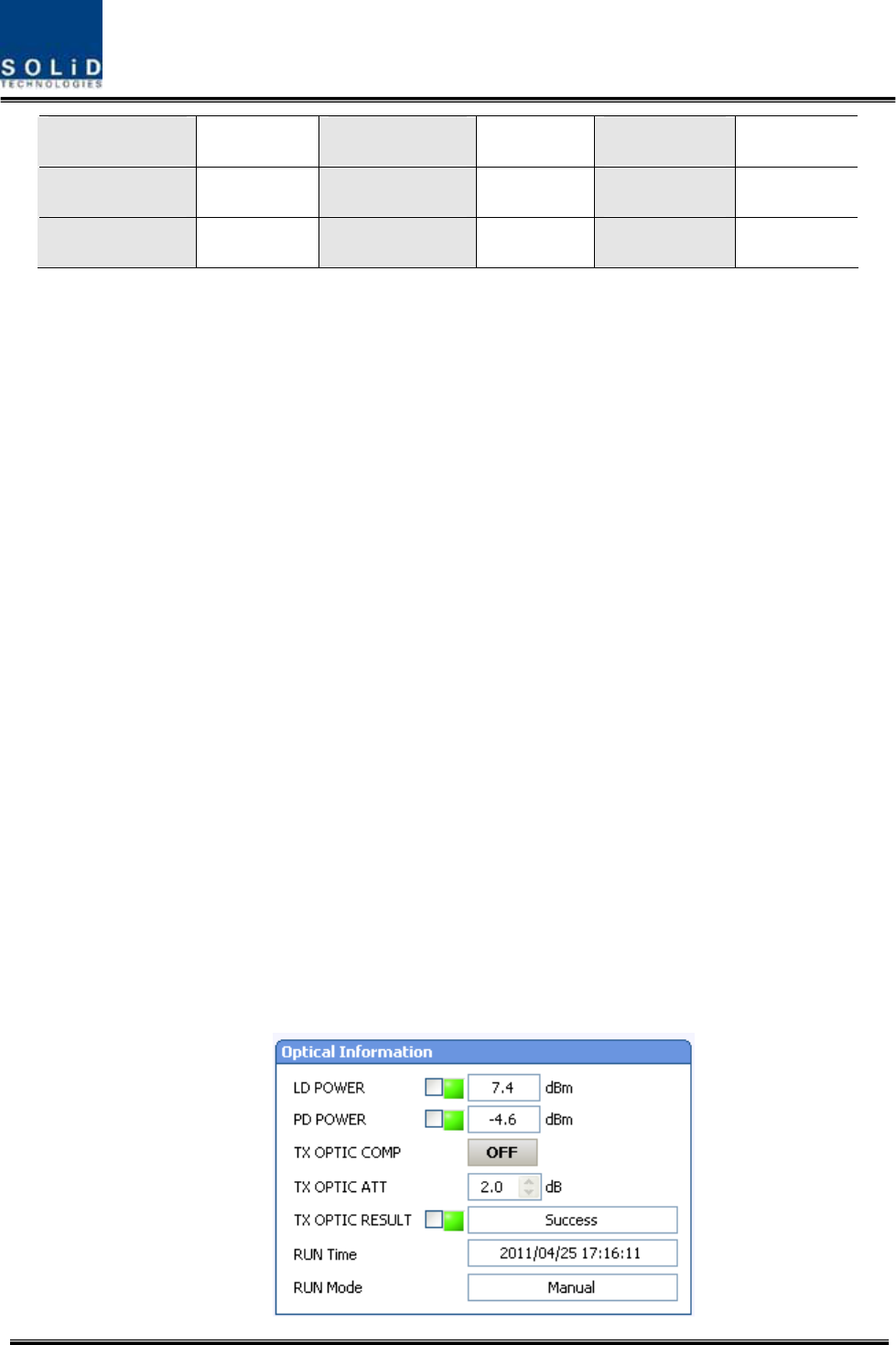
Confidential&Proprietary121/122 SC‐DAS
‐12dBm8dB ‐1dBm19dB+9dBm29dB
‐11dBm9dB0dBm20dB+10dBm30dB
‐10dBm10dB
7.5 Inputpowerlimitfunction(TXInputALC)
TheDAShasaTXinputALCfunctionattheBIUtolimitlevelwheninputpowerisincreased
abovelevelbyoperatedinputAGCfunction
Normally,therearenomorethantwoinputportsintheMDBUoftheBIU
Forexample,the850cellularbandhastwoinputportstosupportbothVzWandAT&T
Thesetwoinputpowersmaybedifferentfromeachother.TheDAShasaninputattenuator
infirststageoftheMDBU.ThroughinputAGCfunction,theinputATTisadjustedaccording
totheinputpower.Ifinputpowerincreases,theinputATTisadjustedagaintolimit
increasedinputpowerandiftheinputpowerdecreases,theinputATTwillreturntothe
initialATTsetting.
7.6 Opticallosscompensation
TheDAShasthefunctionofautomaticallycompensatingforopticalloss.Itcandothework
forupto5dBoofopticalloss.Set“TXOPTICCOMP”ofROUas"ON."Opticalcompensation
ofROUcannotbemadewithoutcommunicationtotheODUorOEU.For1dBoofoptical
loss,basicTXOPTICATTis1dB;for5dBoofopticalloss,TXOPTICATTis4dB.OPTICCOMP
worksonlyonetimebeforeitstaysdormant.
ThefigurebelowshowsascreenforOPTICInformationintheROUGUI.
LDPOWERreferencestheoutputlevelofROULaserDiode,whichissenttoaupperunitby
ROU.PDPOWERreferencestheinputlevelofPhotoDiodetobereceivedfromaupperunit.

Confidential&Proprietary122/122 SC‐DAS
Figure7.2–Opticallossinformation
Duringopticalcompensation,theResultwindowshows"Processing"andthenaresult
valueisdisplayed.Therearethreetypesofresultsasfollows:
1. Success:Theopticalcompensationisnormallycompeted
2. OverOpticLoss:Generatedopticallossexceed5dBoormore.
3. CommunicationFail:CommunicationwithROUisunderpoorcondition.