SOLiD 700FB8085 Alliance_2W User Manual MB DAS

SOLiD, Inc. Alliance_2W MB DAS

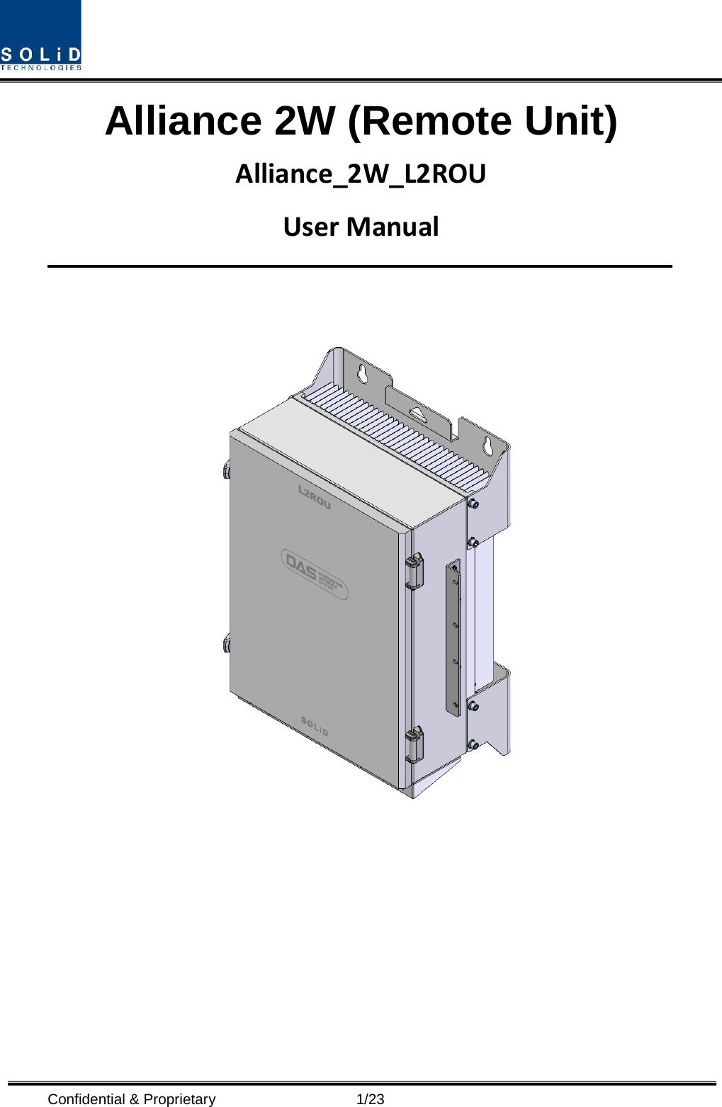
Alliance 2W_Users manual-FCC_Rev1

 Confidential & Proprietary                       1/23 Alliance 2W (Remote Unit) Alliance_2W_L2ROU User Manual
 Confidential & Proprietary                       2/23 REVISION HISTORY Version Issue Date No. of Pages Initials Details of Revision Changes V 1.0 Feb. 23, 2016    Original                                                                                                          Technical Support SOLiD serial numbers must be available to authorize technical support and/or to establish a return authorization for defective units. The serial numbers are located on the back of the unit, as well as on the box in which they were delivered. Additional support information may be obtained by accessing the SOLiD Tehcnology, Inc. website at www.st.co.kr or send email at sjkim@st.co.kr    This manual is produced by Global Business Division Business Team 1. Printed in Korea.
 Confidential & Proprietary                       3/23 Contents Section1 Safety & Certification Notice ................................................................. 5 Section2 System Overview .................................................................................... 9 2.1 Purpose ....................................................................................................... 10 2.2 Alliance 2W ................................................................................................. 11 2.3 Dimension ................................................................................................... 12 Section3 System Installation ............................................................................... 13 3.1 L2ROU Installation ..................................................................................... 13 3.1.1 L2ROU Enclosure installation ............................................................. 13 3.1.2 L2ROU Power Cabling ......................................................................... 17 3.1.3 Optical Cabling ..................................................................................... 18 3.1.4 GND Terminal Connection ................................................................... 19 3.1.5 Coaxial cable and Antenna Connection .............................................. 19 3.1.6 Insertion of L2RDU ............................................................................... 20 3.1.7 L2RDU Specifications Per band .......................................................... 20
 Confidential & Proprietary                       4/23 Contents of Figure Figure 3.1 – L2ROU Outer Look ................................................................. 12 Figure 3.2 – How to install L2ROU ............................................................. 14 Figure 3.3 – Dimension used to install L2ROU on the WALL .................. 14
 Confidential & Proprietary                       5/23 Section1                                             Safety & Certification Notice
 Confidential & Proprietary                       6/23 “Only qualified personnel should handle the DAS equipment. Any person involved in installation or service of the DAS should understand and follow these safety guidelines.”      - Obey all general and regional installation and safety regulations relating to work on high voltage installations, as well as regulations covering correct use of tools and personal protective equipment.  - The power supply unit in repeaters contains dangerous voltage level, which can cause electric shock. Switch the mains off prior to any work in such a repeater. Any local regulations are to be followed when servicing repeaters.  - When working with units outdoors, make sure to securely fasten the door or cover in an open position to prevent the door from slamming shut in windy conditions..  -  Use this unit only for the purpose specified by the manufacturer. Do not carry out any modifications or fit any spare parts which are not sold or recommended by the manufacturer. This could cause fires, electric shock or other injuries.    - Any DAS system or Fiber BDA will generate radio (RF) signals and continuously emit RF energy. Avoid prolonged exposure to the antennas. SOLiD recommends maintaining a 3-foot minimum clearance from the antenna while the system is operating.  -  Do not operate this unit on or close to flammable materials, as the unit may reach high temperatures due to power dissipation.  -  Do not use any solvents, chemicals, or cleaning solutions containing alcohol, ammonia, or abrasives on the DAS equipment. Alcohol may be used to clean fiber optic cabling ends and connectors.  - To prevent electrical shock, switch the main power supply off prior to working with the DAS System or Fiber BDA. Never install or use electrical equipment in a wet location or during a lightning storm.  - Do not look into the ends of any optical fiber or directly into the optical transceiver of any digital unit. Use an optical spectrum analyzer to verify active fibers. Place a protective cap over any radiating transceiver or optical fiber connector to avoid the potential of radiation exposure.  - Allow sufficient fiber length to permit routing without severe bends.  - For pluggable equipment, make sure to install the socket outlet near the equipment so that it is easily accessible.  - A readily accessible disconnect device shall be incorporated external to the equipment.    - This power of this system shall be supplied through wiring installed in a normal building.
 Confidential & Proprietary                       7/23 If powered directly from the mains distribution system, it shall be used additional protection, such as overvoltage protection device.  - Only 50 ohm rated antennas, cables and passive equipment shall be used with this remote.   Any equipment attached to this device not meeting this standard may cause degradation and unwanted signals in the bi-directional system.    All components connected to this device must operate in the frequency range of this device.  - Only 50 ohm rated antennas, cables and passive components operating from 150 - 3 GHz shall be used with this device.  - The following notice: "The Manufacturer's rated output power of this equipment is for single carrier operation. For situations when multiple carrier signals are present, the rating would have to be reduced by 3.5 dB, especially where the output signal is re-radiated and can cause interference to adjacent band users. This power reduction is to be by means of input power or gain reduction and not by an attenuator at the output of the device."  -  The head end unit must always be connected to the Base Station using a direct cabled connection.    This system has not been approved for use with a wireless connection via server antenna to the base station.  - Access can only be gained by SERVICE PERSONS or by USERS who have been instructed about the reasons for the restrictions applied to the location and about any precautions that shall be taken; and - Access is through the use of a TOOL or lock and key, or other means of security, and is on trolled by the authority responsible for the location.  - Signal booster warning label message should include    - Certification    FCC: This equipment complies with the applicable sections of Title 47 CFR Parts 15,22,24,27 and 90(Class B)
 Confidential & Proprietary                       8/23   UL/CUL: This equipment complies with UL and CUL 1950-1  Standard for safety for information technology equipment,including electrical business equipment   FDA/CDRH: This equipment uses a Class 1 LASER according to FDA/CDRH Rules.This product conforms to all applicable standards of 21 CFR Chapter 1, Subchaper J, Part 1040
 Confidential & Proprietary                       9/23 Section2                                          System Overview            2.1 Purpose 2.2 Alliance 2W
 Confidential & Proprietary                      10/23 2.1 Purpose Alliance 2W is a coverage system for in-building services delivering voice and data in high quality and for seamlessly. As a distributed antenna system, it provides analog and digital phone systems that are served in multiple bands through one antenna. The system covers general public institutions and private facilities.  Shopping malls  Hotels  Campus areas  Airports  Clinics  Subways  Multi-use stadiums, convention centers, etc.  The system helps improve in-building radio environments in poor condition and make better poor RSSI and Ec/Io. By providing communication services at every corner of buildings, the system enables users to make a call at any site of buildings.   The system uses both analog (AMPS) and digital (TDMA, CDMA and WCDMA) methods. The  Alliance 2W system supports communication standards and public interface protocols in worldwide use.  Frequencies: VHF,UHF, 700MHz, 800MHz,850MHz 900MHz,1900MHz,2100MHz, etc.    Voice protocols: AMPS,TDMA, CDMA,GSM,IDEN, etc.  Data protocols: EDGE,GPRS,WCDMA,CDMA2000,Paging, etc.  Alliance 2W is in modular structure per frequency. To provide desired frequency in a building, all you need to do is to insert a corresponding frequency module into each unit. As it delivers multiple signals with one optical cable, the system, in one-body type, does not require additional facilities whenever new frequency is added. The system is featured with the following:  Flexibiltiy & Scalabiltiy  Support fiber-optic ports up to 39  Clustering multiple-buildings (campus) as one coverage     Modular structures  Modular frequency upgrade     Plug-in type module    Multi-Band, Multi Operator
 Confidential & Proprietary                      11/23  Signals with a plurality of service provider transmit simultaneously      Support multi-operator in a band    Low OPEX / CAPEX  Compact design    Upgradable design    Easy installation and maintenance  Web Based SNMP or GSM Modem or UDP support (Optional)  2.2 Alliance 2W L2ROU receives TX optical signals from ODU or OEU and converts them into RF signals. The converted RF signals are amplified through High Power Amp in a corresponding L2RDU, combined with Multiplexer module and then radiated to the antenna port. When receiving RX signals through the antenna port, this unit filters out-of-band signals in a corresponding L2RDU and sends the results to Remote Optic Module to make electronic-optical conversion of them. After converted, the signals are sent to a upper device of ODU or OEU. L2ROU can be equipped with up to three L2RDUs (Remote Drive Unit) and the module is composed of maximal Dual Band.
 Confidential & Proprietary                      12/23 2.3 Dimension   Figure 3.1 – L2ROU Outer Look  L2ROU is designed in a cabinet, and provides the following functions and features.  Item Spec. Remark Size(mm) 482.6(19“) x 268.5 x560, Including Bracket Weight 35.45 Kg Full Load Power consumption 235 W Operating Temperature -10 to +50°C Ambient Temperature
 Confidential & Proprietary                      13/23 Section3                                           System Installation            3.1 L2ROU Installation 3.1.1 L2ROU Enclosure installation L2ROU is designed to be water- and dirt-proof. The unit has the structure of One-Body enclosure. It satisfies water-proof and quake-proof standards equivalent of NEMA4. L2ROU can be mounted into either of a 19” Standard Rack or on a Wall.   Basically, L2ROU has both of a Wall Mount Bracket and a Rack Mount Bracket. Depending on the use of the Rack Mount Bracket, the bracket can be removed. The following shows dimension of the fixing point for the Wall Mount Bracket.
 Confidential & Proprietary                      14/23  Figure 3.2 – How to install L2ROU  Figure 3.3 – Dimension used to install L2ROU on the WALL
 Confidential & Proprietary                      15/23 L2ROU Wall Mount Installation  Turn M12 Fixing Screws by half on the wall and fully fix the screw with a Wall Mount Bracket on it. For convenience, the Wall Mount Bracket has fixing holes to let you easily mount an enclosure.   Turn the M5 Wrench Bolt by half at each side of the Heatsink of the enclosure.    Put the enclosure with the M5 Wrench Bolt fixed on the fixing groove and fix the M5 Wrench Bolts into the remaining fixing holes. In this case, you will use 12 M5 Wrench Bolts in total except bolts used for the fixing groove.
 Confidential & Proprietary                      16/23 L2ROU Rack Mount Installation Like other units, L2ROU is designed to be inserted into a rack. The unit occupies around 13U of space except cable connection.                   L2ROU component L2ROU has the following components: No. Unit Description Remark Common Part Enclosure Including Rack & Wall cradle 1EA RCPU  -  1EA R_OPTIC With SC/ACP adaptor 1EA RPSU Alternative DC-48V or AC 120V   1EA Multi-Plexer  -  1EA Power Cable - MS Connector with 3 hole to AC 120 plug(AC) - MS Connector with 2 lug termination(DC)  Optional Part L2RDU+BPF 1900P_AWS13, 8085_700FB, 2500_60TDD 2300_WCS (L2RDU) Up to 3EA to be inserted Dry contact Relay Sub Used    to connect L2ROU to external alarm unit
 Confidential & Proprietary                      17/23 board  Basically, the common part of L2ROU should have an enclosure and it is equipped with RCPU to inquire and control state of each module, R_OPTIC to make both of electronic-optical and optical-electronic conversions, RPSU to supply power for L2ROU and a Multi-Plexer to help share multiple TX/RX signals through one antenna. It should have Power Cable for external rectifier or to supply required power. In addition, L2RDU can be inserted and removed to provide service for desired band (Optional).  3.1.2  L2ROU Power Cabling L2ROU supports both of DC-48V and AC120V of input power. As RPSU for DC-48 and RPSU for AC120V are separated from each other, you need to select one of them in case of purchase order. RPSU for DC -48V and RSPU for AC 120V have the same configuration and capacity while each of the units uses different input voltage from each other.  The following figure shows configuration of RPSUs for DC -48V and AC 120V.
 Confidential & Proprietary                      18/23 MC Connector numbering Lug Naming RPSU Terminal naming Remark AC DC AC DC A  AC_H  -48V AC-H  -48V   B  AC_N GND AC-N  IN_GND   C  GND DC NC FG FG    Check if the connection is the same as one seen in the table above and make sure to turn the power ON.  3.1.3 Optical Cabling L2ROU makes optical-electronic conversion of TX signals from upper ODU and OEU and makes electronic- optical conversion of RX signals. L2ROU has one optical module in it. As WDM is installed in the R_OPTIC module, two pieces of wavelength (TX:1310nm, RX:1550nm) can be sent/received with one optical core at the same time. L2ROU has SC/APC of optical adaptor type. For optical adaptor, SC/APC type can be used. To prevent the optical access part from being marred with dirt, it should be covered with a cap during move. When devices are connected through optical cables, you need to clear them using alcohocol to remove dirt.   Optical cables should be inserted into Optic Port outside of L2ROU. Using an optical slack devices in L2ROU, you need to coil around one or two roll of cables to be connected with the optical adaptor of ROPTIC.
 Confidential & Proprietary                      19/23 At this time, curvature of the optical cable should be at least 10Ø to prevent insertion loss from being increased. Through GUI, check if PD value of ROPTIC is in a tolerable range (+4~-1dBm).  3.1.4 GND Terminal Connection L2ROU has one GND terminal port where is on bottom side, like below    -  Take off the GND terminal port from enclosure and connect to ground cable, then fix it the position of enclosure again -  The opposite end of the ground cable should connect to the communication GND of building      3.1.5 Coaxial cable and Antenna Connection -  The coaxial cables which are connected to antenna distribued network connect to antenna port of L2ROU. Before connection, check the VSWR value of coaxial cable whether it is within specification using SITEMASTER . -  At this time, check if the Return loss have above 15dB or VSWR have below 1.5 -  The part of antenna connection fasten to port not to be loosed and not to be injected the dusty and insects
 Confidential & Proprietary                      20/23 - The antenna connected to L2ROU is only serviced in inbuilding        3.1.6 Insertion of L2RDU L2ROU has slots to enable up to three L2RDU modules to be inserted into the unit. You can insert a L2RDU into any slot. It is not possible to provide services with a L2RDU module alone; you need to connect the module with Cavity BPF in any case. The table below shows types of L2RDU and CAVITY BPF: No Unit naming Cavity BPF RF CABLE 1  L2RDU 8085_700FB(2W) -  TX CABLE 1EA RX CABLE 1EA 2  L2RDU 1900P_AWS13(2W) -  TX CABLE 1EA RX CABLE 1EA 3  L2RDU 2500_60TDD 2.5TDD BPF TRX CABLE 1EA (Common)  3.1.7 L2RDU Specifications Per band Standard   Unit naming Description Frequency range TX(MHz) RX(MHz) LTE 700FB Long Term Evolution 729 to 756 699 to 716 777 to 787 iDEN + Cellular 8085 Public safety Cellular 862 to 894 817 to 849 PCS 1900P PCS 1930 to 1995 1850 to 1915 AWS-1 + AWS-3  AWS13 AWS 2110 to 2180 1710 to 1780 TDD LTE 2500_60TDD TDD 2497.8~2687.4 2497.8~2687.4
 Confidential & Proprietary                      21/23  700MHz Long Term Evolution Parameters Typical Remarks TX RX   Bandwidth 27MHz 27MHz   Output power +33dBm +0dBm Total System Gain  53dB 50dB   input and output impedances 50 ohm   50 ohm      800MHz+850MHz Public safety & Cellular Parameters Typical Remarks TX RX   Bandwidth 32MHz 32MHz   Output power +33dBm +0dBm Total System Gain  53dB 50dB   input and output impedances 50 ohm   50 ohm      1900MHz PCS Parameters Typical Remarks TX RX   Bandwidth 65MHz 65MHz   Output power  +33dBm +0dBm Total System Gain 53dB 50dB   input and output impedances 50 ohm   50 ohm
 Confidential & Proprietary                      22/23  1700MHz&2100MHz AWS-1 + AWS-3 Parameters Typical Remarks TX RX   Bandwidth 70MHz 70MHz   Output power  +33dBm +0dBm Total System Gain 53dB 50dB   input and output impedances 50 ohm   50 ohm      2500MHz 2.5TDD Parameters Typical Remarks TX RX   Bandwidth 189.6MHz 189.6MHz   Output power  +32.5 dBm  -20dBm  @ RDU Port System Gain 52dB  30dB   input and output impedances 50 ohm   50 ohm
 Confidential & Proprietary                      23/23    RF Radiation Exposure   This equipment complies with RF radiation exposure limits set forth for an uncontrolled environment. This transmitter must not be co-located or operating in conjunction with any other antenna or transmitter. RF exposure will be addressed at time of installation and the use of higher gain antennas may require larger separation distances.   Part 27.5 Antennas must be installed in accordance with FCC 27.50.    With 17dBi gain antennas the height of the antenna above average terrain (HAAT) is permitted over 1372m.  For different gain antennas refer to the relevant rules.  FCC notice - Use of unauthorized antennas, cables, and/or coupling devices not conforming with ERP/EIRP and/or indoor‐only restrictions is prohibited.  - Home/ personal use are prohibited.

Navigation menu