SOLiD 700LTEF850C Low Power Communication Device User Manual
SOLiD, Inc. Low Power Communication Device
SOLiD >
User Manual
Conf
i
8
9
10
i
dential & Pr
o
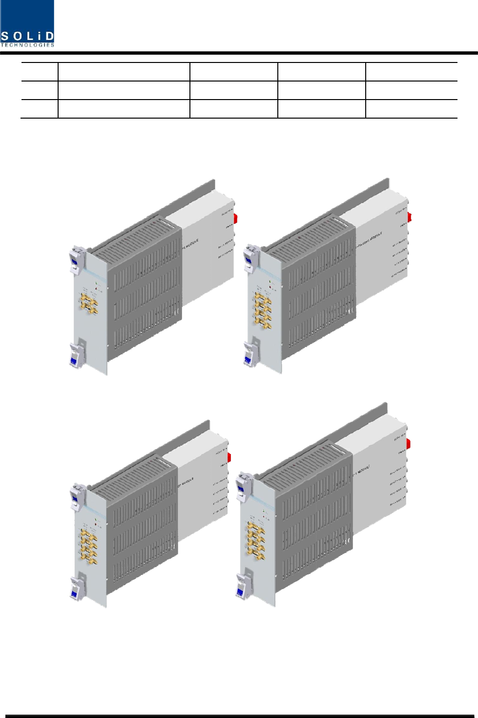
700LTEF SI
S
700LTEF MI
700LTEF+8
5
o
prietary
S
O
MO
5
0C
800PS
1900PCS
Sing
Sing
Dual
28/13
9
le Band
le Band
Band
9
2 Port
4 Port
4 Port
800
P
P
S+900I+P
a
A
WS-1
2 Port
4 Port
4 Port
a
ging
Conf
i
i
dential & Pr
o
o
prietary
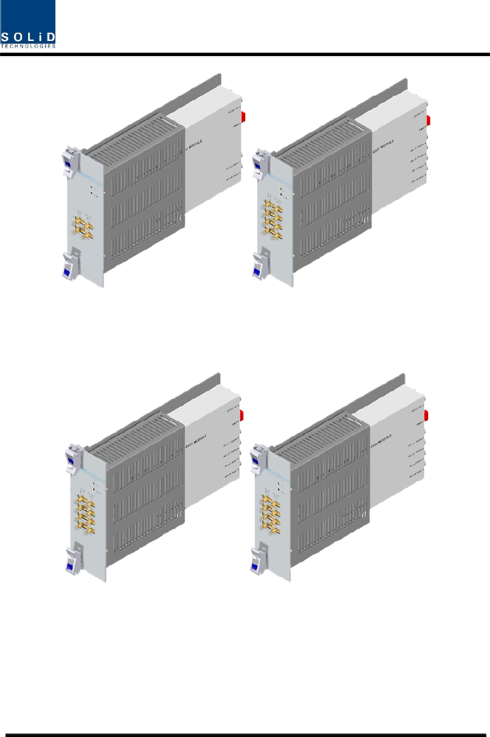
8
850
C
8
50C
C
+700LTE
C
29/13
9
C
9
850
C
700LTE
F
C
+700PS
F
+850C
Conf
i
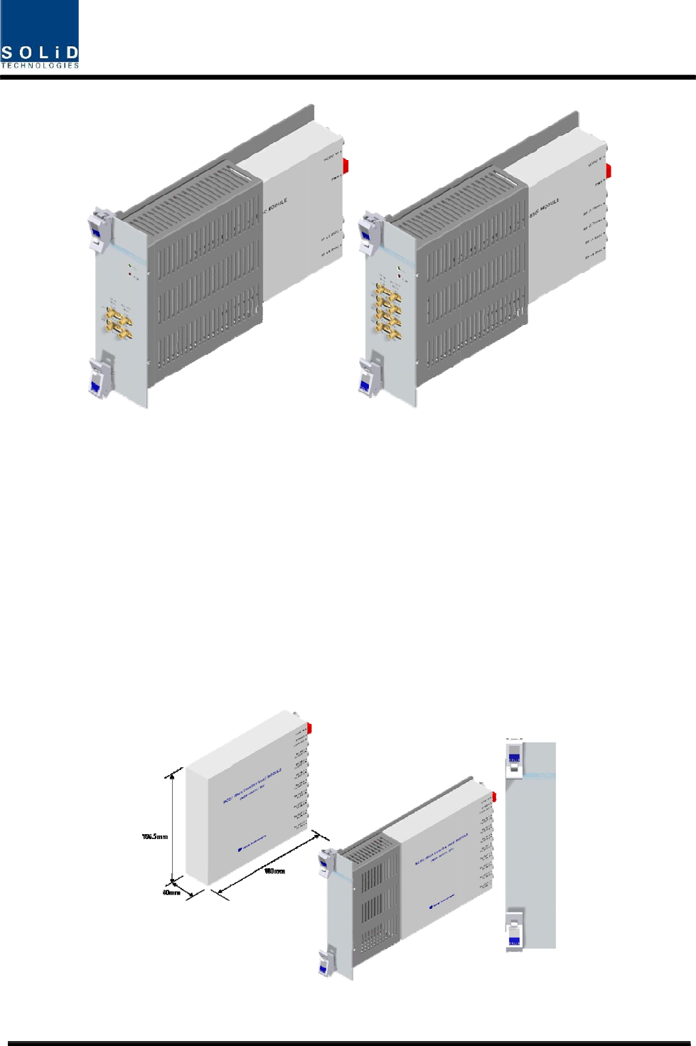
2) M
a
MCD
sign
a
them
MDB
form
The
u
cont
r
i
dential & Pr
o
a
in Com/Di
v
U combines
a
ls to four O
to ROU. It
a
Us. In this
c
with RX sig
n
u
nit has a p
o
r
ol.
o
prietary
v
Unit (MCD
U
TX signals
t
DUs. This u
a
lso combin
e
c
ase, the un
i
n
als, and the
o
rt to interfa
c
700LT
E
Figure 4.
3
U
)
t
hat are deli
v
nit adds sig
n
e
s RX signa
i
t extracts si
g
n delivers th
c
e with VHF
&
Figure 4.
4
E
F SISO
30/13
9
3
– MDBU
O
v
ered from
M
n
als of FSK
ls from up t
o
g
nals of FS
K
e signals to
&
UHF signal
s
4
– MDBU
O
9
O
uter Look
M
DBU per fr
e
modem to
t
o
four ODUs
K
modems,
w
MCU.
s
. It has AT
T
O
uter Look
e
quency ban
t
he TX sign
a
and sends
t
w
hich are s
e
T
for input m
o
700LTEF
d and deliv
e
a
ls before s
e
t
hem to up
t
e
nt in a co
m
o
nitoring an
d
MIMO
e
rs the
e
nding
t
o four
m
bined
d
input
Conf
i
VHF
+
No
1
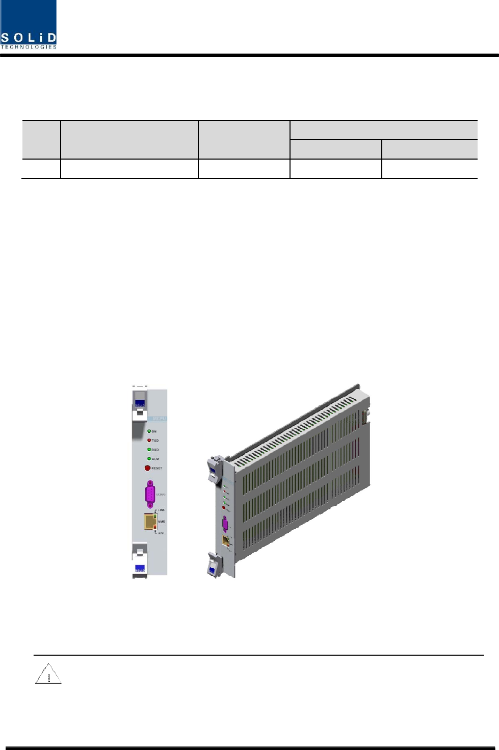
3) M
a
MCP
This
inqui
r
In ad
state
com
m
fault
y
For
a
In th
e
funct
RIS
K
DIP
O
i
dential & Pr
o
+
UHF freq
u
U
n
VHF+UHF
a
in Central
P
U can inquir
e
unit can inq
u
r
e and contr
o
dition, the u
n
of devices
t
m
unication s
t
y
.
a
ccess to up
p
e
Main Cen
t
ion.
CAUTIO
N
K
OF EXPLO
O
SE OF US
E
o
prietary
u
ency band i
n
it naming
P
rocessor
U
e
and contr
o
u
ire and con
t
o
l ROU that
n
it has RS-2
t
hrough PC.
t
ate with R
O
p
er network,
t
ral Process
o
N
SION IF BA
T
E
D BATTERI
ncluding th
e
D
Dual
U
nit (MCPU
)
o
l state of m
o
t
rol state of
f
is connecte
d
32C port for
On the fro
n
O
U. It also h
a
it has a por
t
Figure 4.
5
o
r Unit, a lit
h
T
TERY IS R
ES ACCOR
D
31/13
9
e
following:
D
escription
Band
)
o
dules that a
f
our ODUs i
n
d
with lower
p
serial com
m
n
t panel, it h
a
a
s ALM LE
D
t
to insert Et
h
5
– MCPU
O
h
ium batter
y
EPLACED
B
D
ING TO T
H
9
T
1
re installed i
n
total. Thro
u
p
arts.
m
unication s
o
a
s communi
D
indicator t
o
h
ernet port a
O
uter Look
y
is installed
B
Y AN INCO
H
E INSTRU
C
In/out
R
TX
Port
n BIU.
u
gh commun
o
that it can i
cation LED
o
show whe
t
nd GSM mo
d
for RTC (
R
RRECT TY
P
C
TIONS
R
F Port
RX
1 Por
t
ication, it al
s
nquire and
c
indicator to
t
her a devic
e
d
em in it.
R
eal Time C
o
P
E
t
s
o can
c
ontrol
check
e
gets
o
ntrol)
Conf
i
[INS
T
The
e
the li
f
lithiu
m
of ex
p
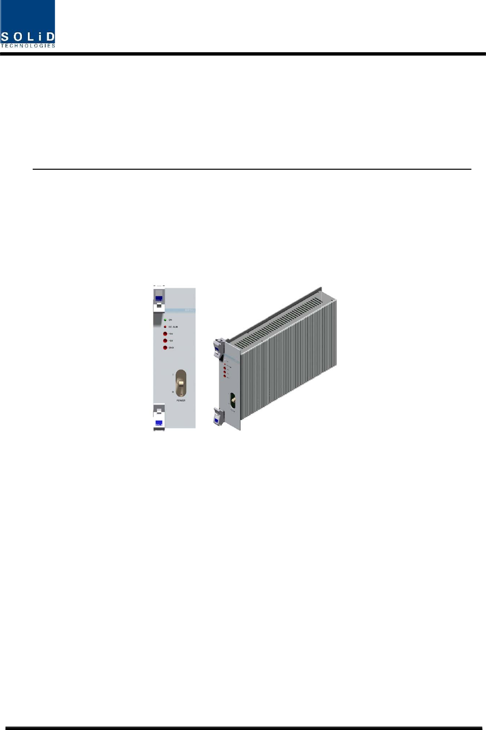
4) M
a
MPS
On t
h
sho
w
4.1.
5
1
i
dential & Pr
o
T
RUCTION]
e
quipment a
f
e span of t
h
m
battery u
n
p
losion.
a
in Power
S
U receives -
4
h
e front pan
e
w
whether ou
t
5
Front/rea
1
)
Front p
a
o
prietary
nd accessor
h
em and na
t
n
less servic
e
S
upply Unit
(
4
8V of input
e
l, this unit
t
put gets fa
u
r panels o
f
a
nel
ies includin
g
t
ional regul
a
e
personnel
c
(
MPSU)
and outputs
has an outp
u
lty.
Figure 4.
6
f
BIU
32/13
9
g
inner lithiu
m
a
tion must b
e
c
onfirmation
+6V and +
9
ut test port
a
6
– MPSU
O
9
m
battery ar
e
e
observed.
has first be
V of DC po
w
a
nd it also
h
O
uter Look
e
to be disp
o
Do not atte
m
en obtained
,
w
er.
h
as DC AL
M
o
sed of safel
y
m
pt to repla
c
,
to avoid a
n
M
LED Indic
a
y
after
c
e the
n
y risk
a
tor to