SOLiD 80PS90IPAR RDU MODULE (800PS/900I/PA) User Manual
SOLiD, Inc. RDU MODULE (800PS/900I/PA)
SOLiD >
User Manual
Confidential & Proprietary 31/136
VHF+UHF frequency band including the following:
No Unit naming Description In/out RF Port
TX RX
1 VHF+UHF Dual Band 1 Port 1 Port
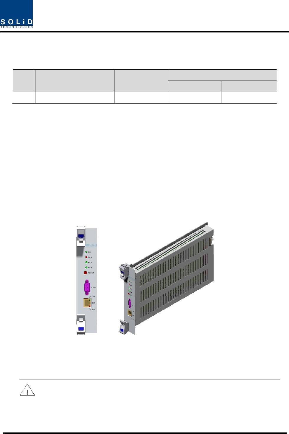
3) Main Central Processor Unit (MCPU)
MCPU can inquire and control state of modules that are installed in BIU.
This unit can inquire and control state of four ODUs in total. Through communication, it also can
inquire and control ROU that is connected with lower parts.
In addition, the unit has RS-232C port for serial communication so that it can inquire and control
state of devices through PC. On the front panel, it has communication LED indicator to check
communication state with ROU. It also has ALM LED indicator to show whether a device gets
faulty.
For access to upper network, it has a port to insert Ethernet port and GSM modem in it.
Figure 4.5 – MCPU Outer Look
In the Main Central Processor Unit, a lithium battery is installed for RTC (Real Time Control)
function.
CAUTION
RISK OF EXPLOSION IF BATTERY IS REPLACED BY AN INCORRECT TYPE
DIPOSE OF USED BATTERIES ACCORDING TO THE INSTRUCTIONS
Confidential & Proprietary 32/136
[INSTRUCTION]
The equipment and accessories including inner lithium battery are to be disposed of safely after
the life span of them and national regulation must be observed. Do not attempt to replace the
lithium battery unless service personnel confirmation has first been obtained, to avoid any risk
of explosion.
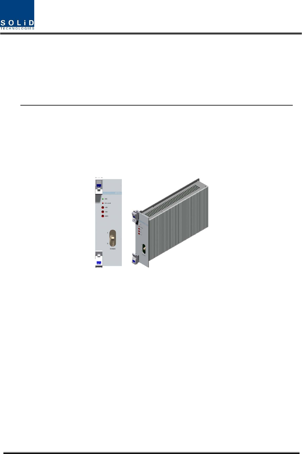
4) Main Power Supply Unit (MPSU)
MPSU receives -48V of input and outputs +6V and +9V of DC power.
On the front panel, this unit has an output test port and it also has DC ALM LED Indicator to
show whether output gets faulty.
Figure 4.6 – MPSU Outer Look
4.1.5 Front/rear panels of BIU
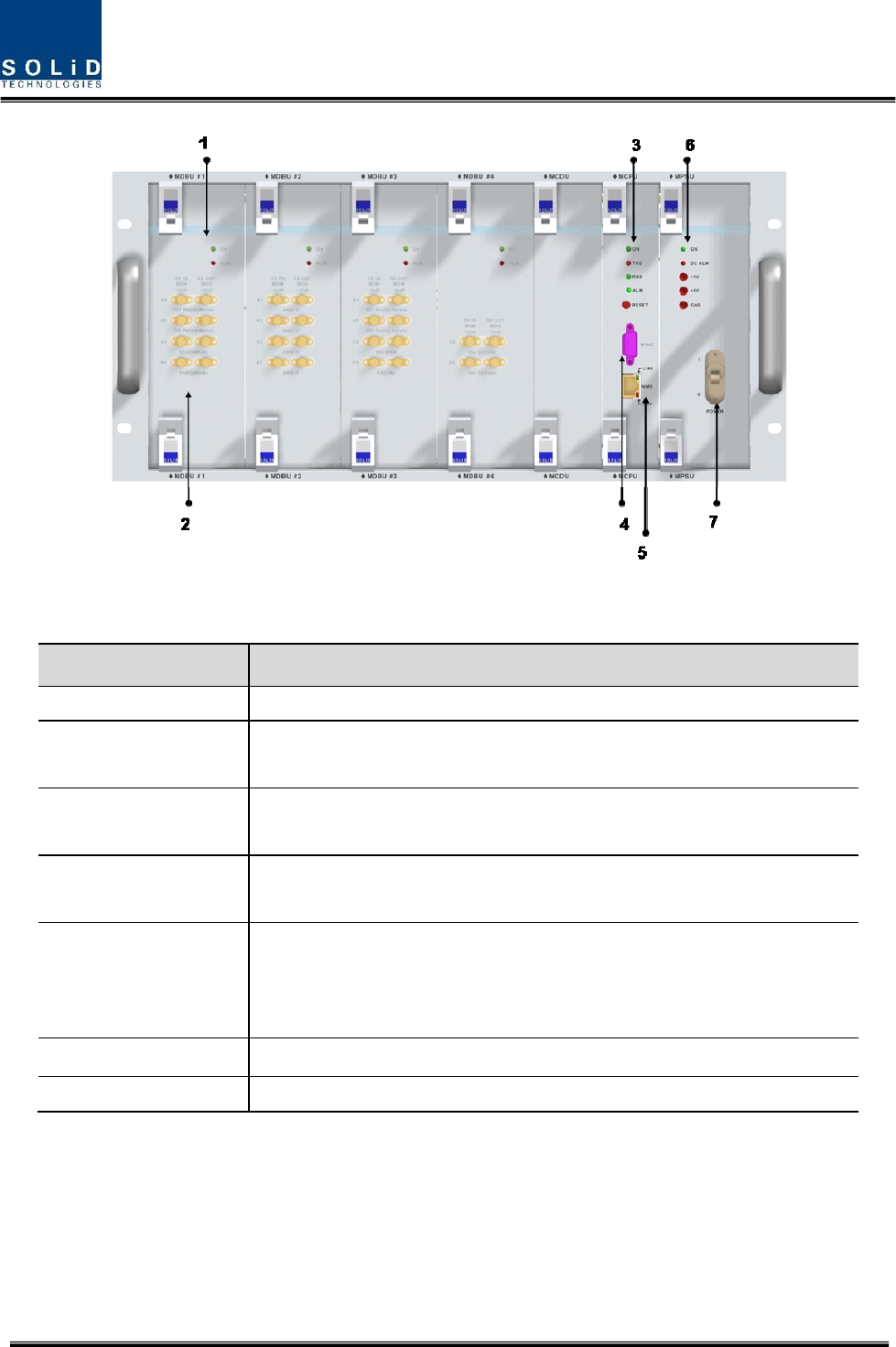
1) Front panel
Confidential & Proprietary 33/136
Figure 4.7 – BIU front panel Outer Look
Item Description
1. MDBU LED LED to show whether MDBU is installed and gets faulty
2. RF Monitor Port 20Db Coupling compared with TX Input Level
20Db Coupling compared with RX Output Level
3. Alarm LED & Reset Communication state with devices, alarm status of the system and reset
switch
4. NMS(RS-232C port) RS-232C port for communication and diagnosis of devices through
PC/laptop
5. NMS(Ethernet port)
Ethernet port for upper network
This equipment is indoor use and all the communication wirings are
limited to inside of the building
6. Pwr Test Port & ALM Output DC power test port and ALM LED to show abnormal state, if any
7. Power switch Power ON/OFF switch
Confidential & Proprietary 34/136
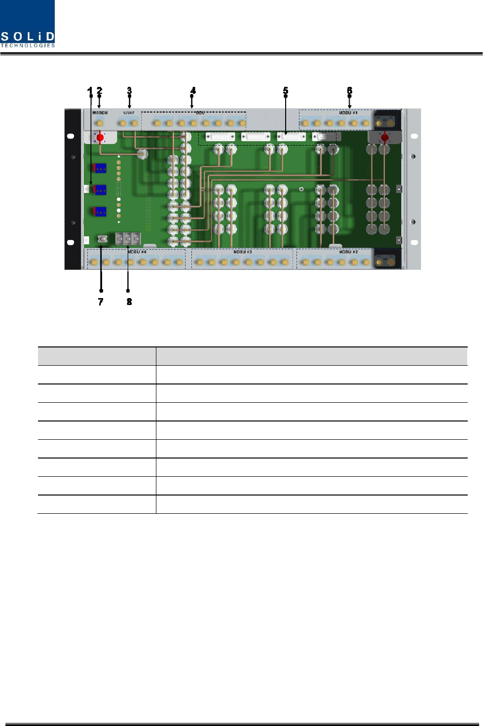
2) Rear panel
Figure 4.8 – Rear panel Outer Look
Item Description
1. External ALM Port Input/output terminal for dry contact
2. GSM Modem Port GSM Modem terminal for upper network (Optional)
3. V/UHF I/O Port RF signal interface terminal of VHF&UHF
4. ODU I/O Port RF signal interface terminal for ODU
5. ODU signal Port Power and signal interface terminal for ODU
6. BTS/BDA I/O Port Input/output interface terminal of BTS/BDA
7. GND Port System ground terminal
8. DC Input Port Input terminal for DC -48V
Confidential & Proprietary 35/136
4.2 ODU (Optic distribution Unit)
ODU receives TX RF signals from upper BIU and converts them into optical signals. The optical
signals are sent to ROU through optical cables. This unit converts optical signals from ROU into
RF signals and sends the converted signals to BIU.
For each shelf of the ODU, up to two DOUs (Donor Optic Unit) can be installed in it.
One DOU is supported with four optical ports. Therefore, one ODU can be connected with eight
ROUs.
Up to four ODUs can be connected with BIU.
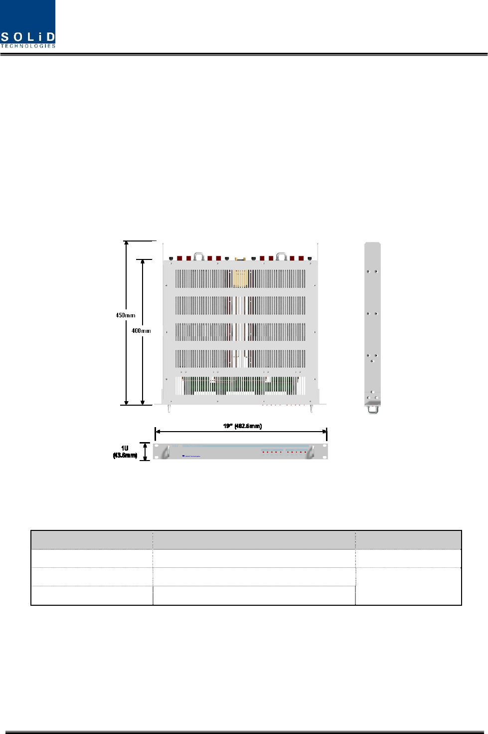
Figure 4.9 – ODU Outer Look
4.2.1 Specifications of ODU
Item Spec. Remark
Size 482.6(19”) x 43.6(1U) x 450 Mm
Weight 5.7 Kg Full Load
Power consumption 27 W
Confidential & Proprietary 36/136
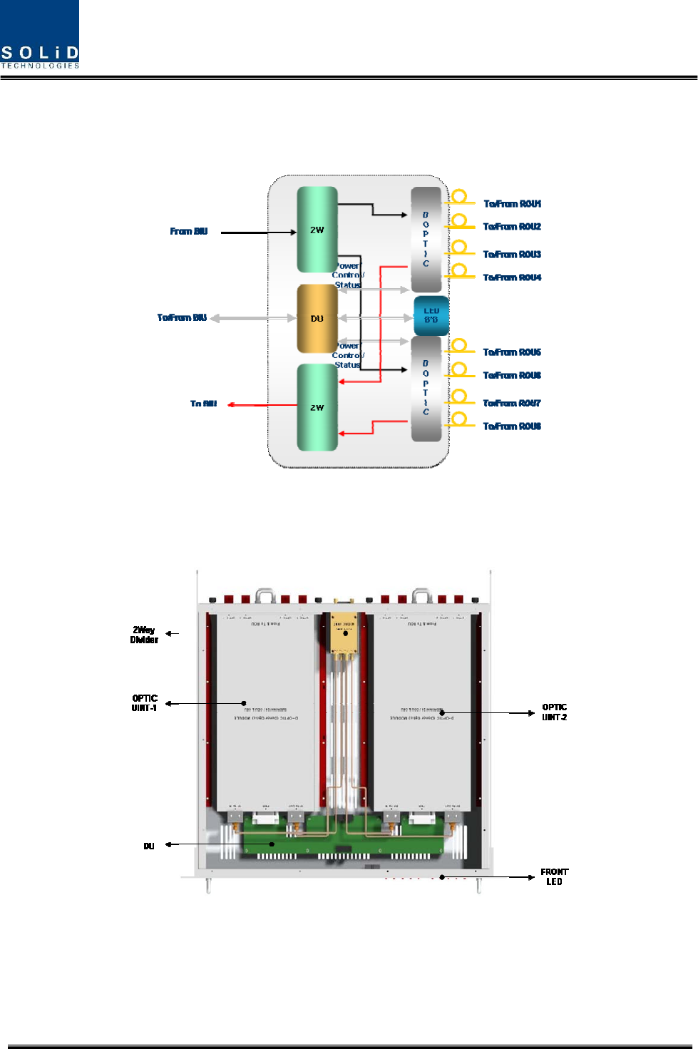
4.2.2 Block Diagram of ODU
4.2.3 ODU parts
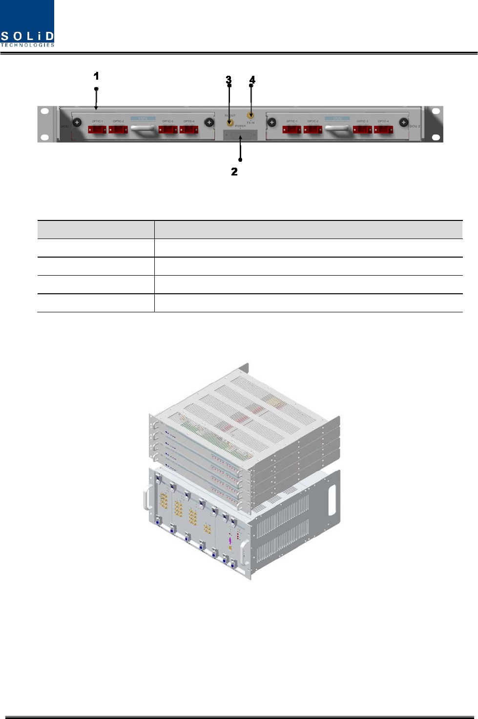
Figure 4.10 – ODU Inner Look
Confidential & Proprietary 37/136
No. Unit Description Remark
1 DOU
DOU
Convert TX RF signals into optical signals;
Convert RX optical signals into RF signals;
Provide up to four optical ports per DOU
Max 2ea
2 2W
2Way Divider
Divide TX RF signals into two;
Combine two RX RF signals into one
3 DU Distribution Unit
Distribute power and signals to DOU
4 Shelf 19” rack, 1U
5 Accessories
15PIN DSUB, Male to female 1pcs
RF Coaxial Cable Assembly 2pcs
4.2.4 Function by unit
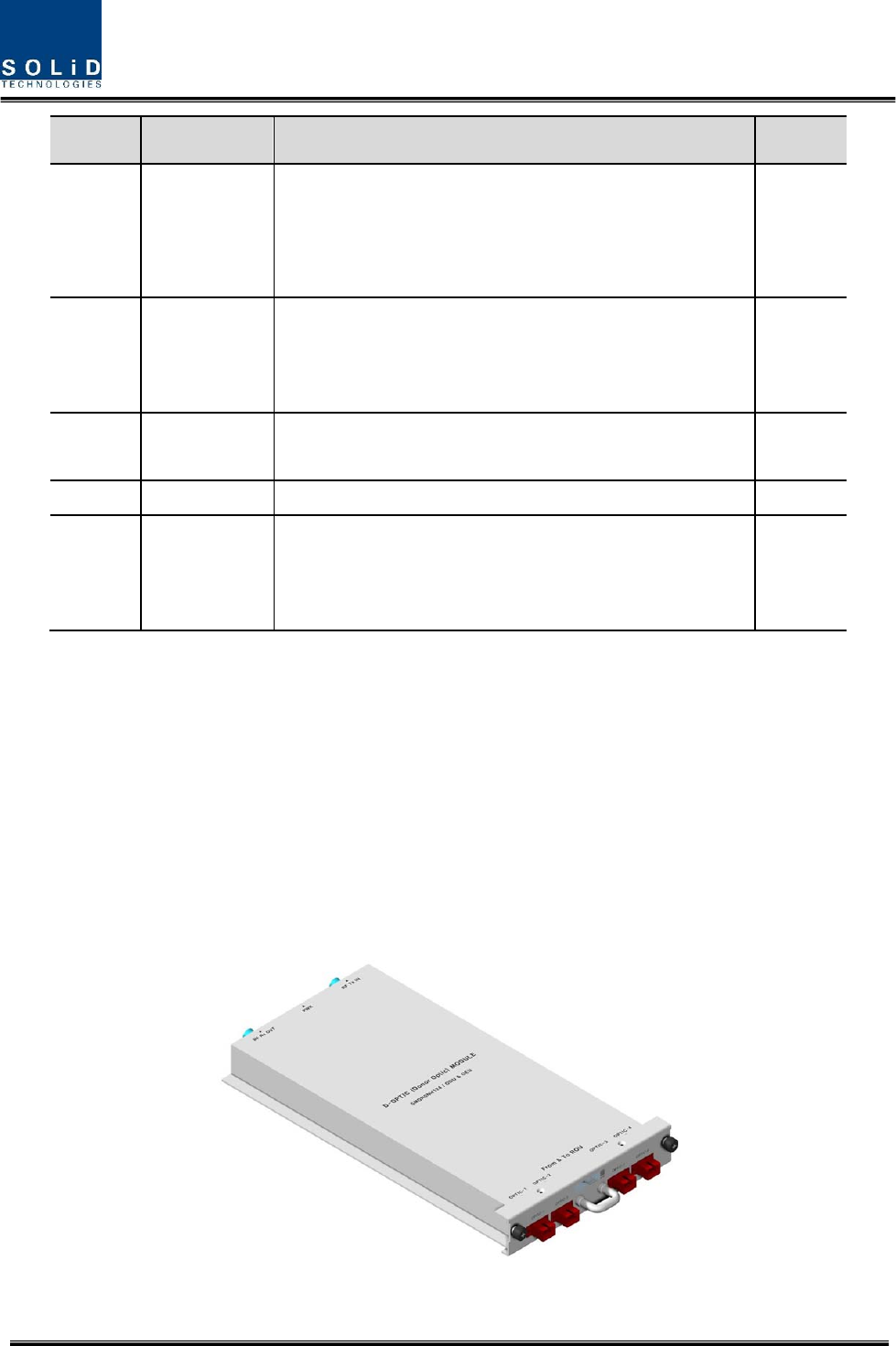
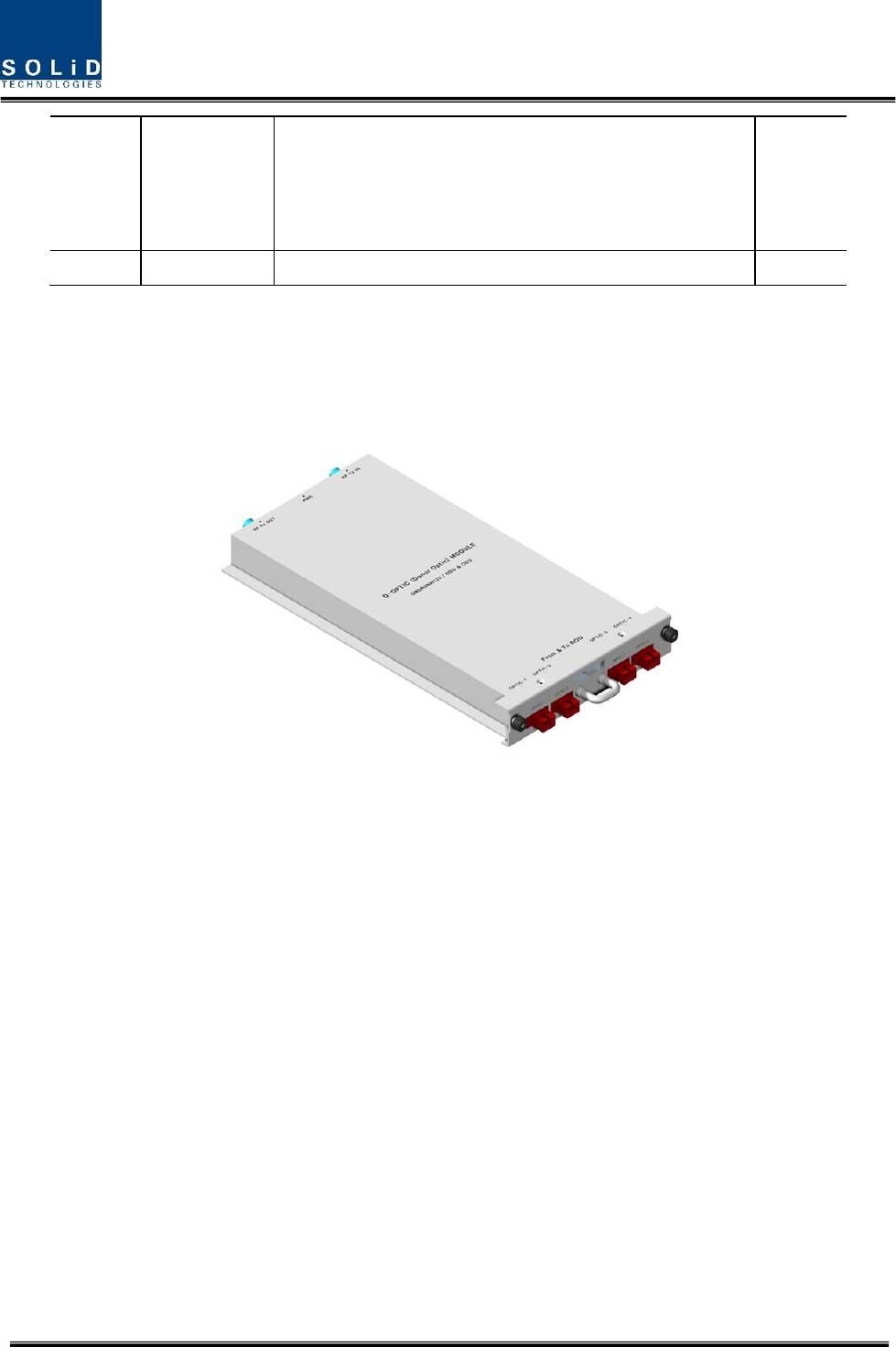
1) Donor Optic Unit (DOU)
DOU makes electronic-optical conversion of TX signals and makes optical-electronic conversion
of RX signals.
With an optic splitter in it, this unit divides optical signals from Laser Diode into four and then
distributes them to each optical port. With a total of four Photo Diodes in RX, DOU makes
optical-electronic conversion of signals received from each optical port. In addition, the unit is
equipped with ATT for optical compensation made in case of optical cable loss.
With internal WDM, it uses only one optical cable to be connected with ROU.
Figure 4.11 – MDBU Outer Look
Confidential & Proprietary 38/136
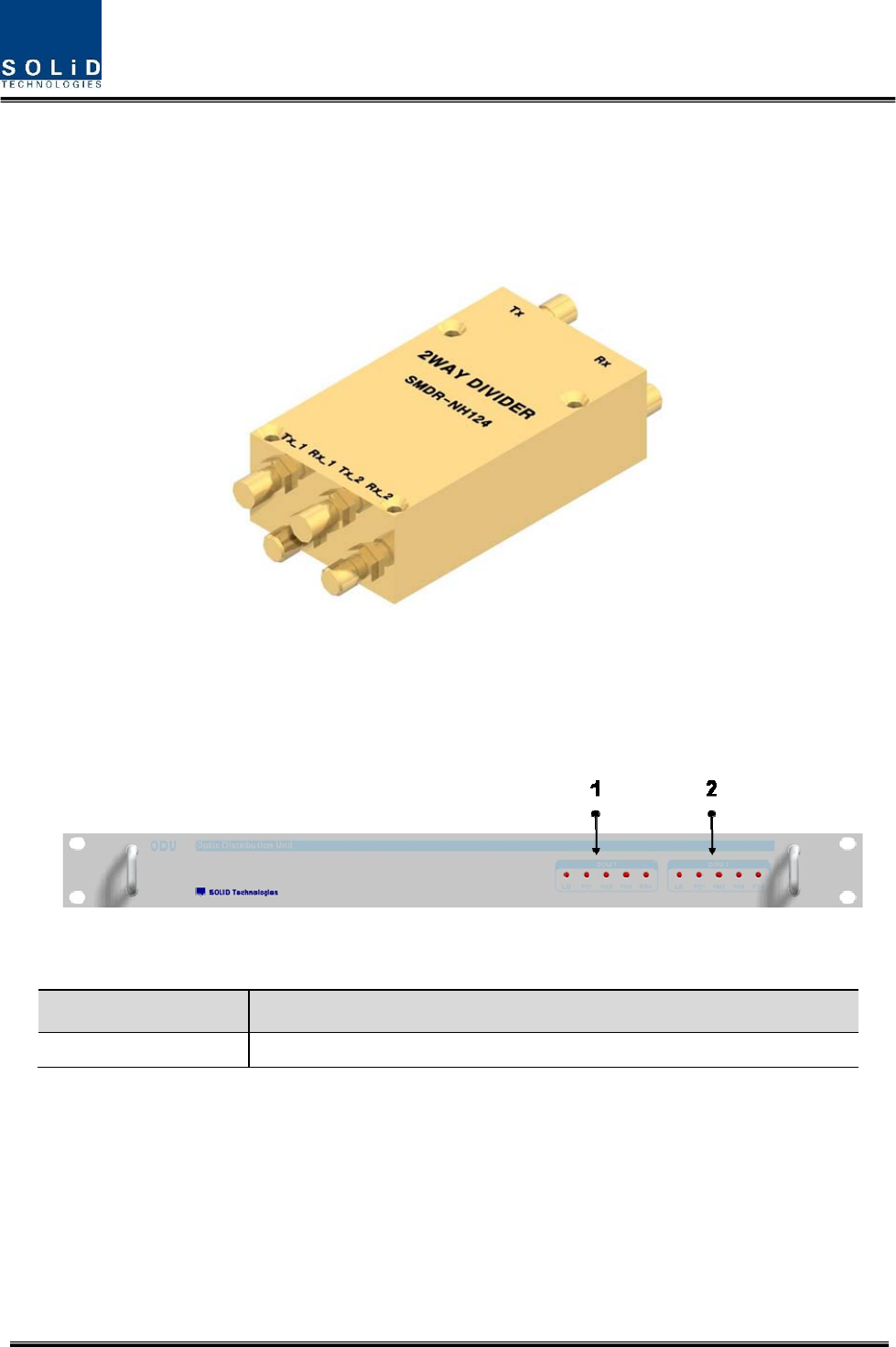
2) 2Way Divider (2W)
2W is equipped with two 2-way splitters in a one-module form and the splitters work for TX/RX
signals, respectively.
Designed in broadband type, the divider combines and divides 2GHz or higher of signals from
FSK modem signals.
Figure 4.12 – 2Way Divider Outer Look
4.2.5 Front/rear panels of ODU
1) Front panel
Figure 4.13 – ODU front panel Outer Look
Item Description
1,2 LED indicator to check DOU module state to see if it is abnormal
2) Rear panel
Confidential & Proprietary 39/136
Figure 4.14 – ODU Rear panel Outer Look
Item Description
1. Optic Port SC/APC optical connector terminal; use one optical cable per ROU.
2. DC I/O Port Terminal to deliver power and state values
3. RX RF Port RX RF signal interface terminal
4. TX RF Port TX RF signal interface terminal
4.2.6 Interface with BIU
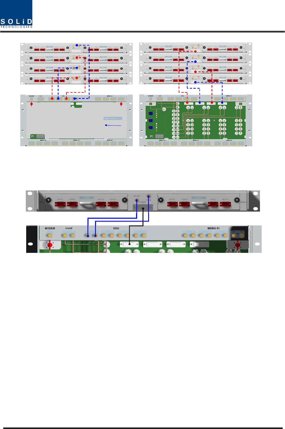
Figure 4.15 – Interface between BIU and ODU
On the top of BIU, up to four ODUs can be stacked.
In this case, it is recommended to stack the units at least 1U of an interval between BIU, for
heat from BIU may climb up to ODU, which may cause flame.
Confidential & Proprietary 40/136
As seen in the figure below, connect the coaxial cable for TX and another coaxial cable for RX
with corresponding ports at the rear of BIU. For power supply and communication, connect
15Pin D-Sub Connector cable with a corresponding port.
4.3 OEU (Optic Expansion Unit)
OEU is mainly used to remotely deliver signals for Campus clusters. At the upper part, this unit
combines with ODU and receives TX optical signals to convert them into RF signals. Then, it
regenerates the signals to secure S/N feature and converts them into optical signals. The
signals are sent to ROU through optical cables. When it receives RX optical signals from ROU,
the unit converts them into RF signals to regenerate the signals and then converts them into
optical signals to send them to ODU.
In OEU, one shelf can be equipped with up to two DOUs. The DOU is the same as the module
used for ODU. Up to two OEUs can be connected with ODU.
Confidential & Proprietary 41/136
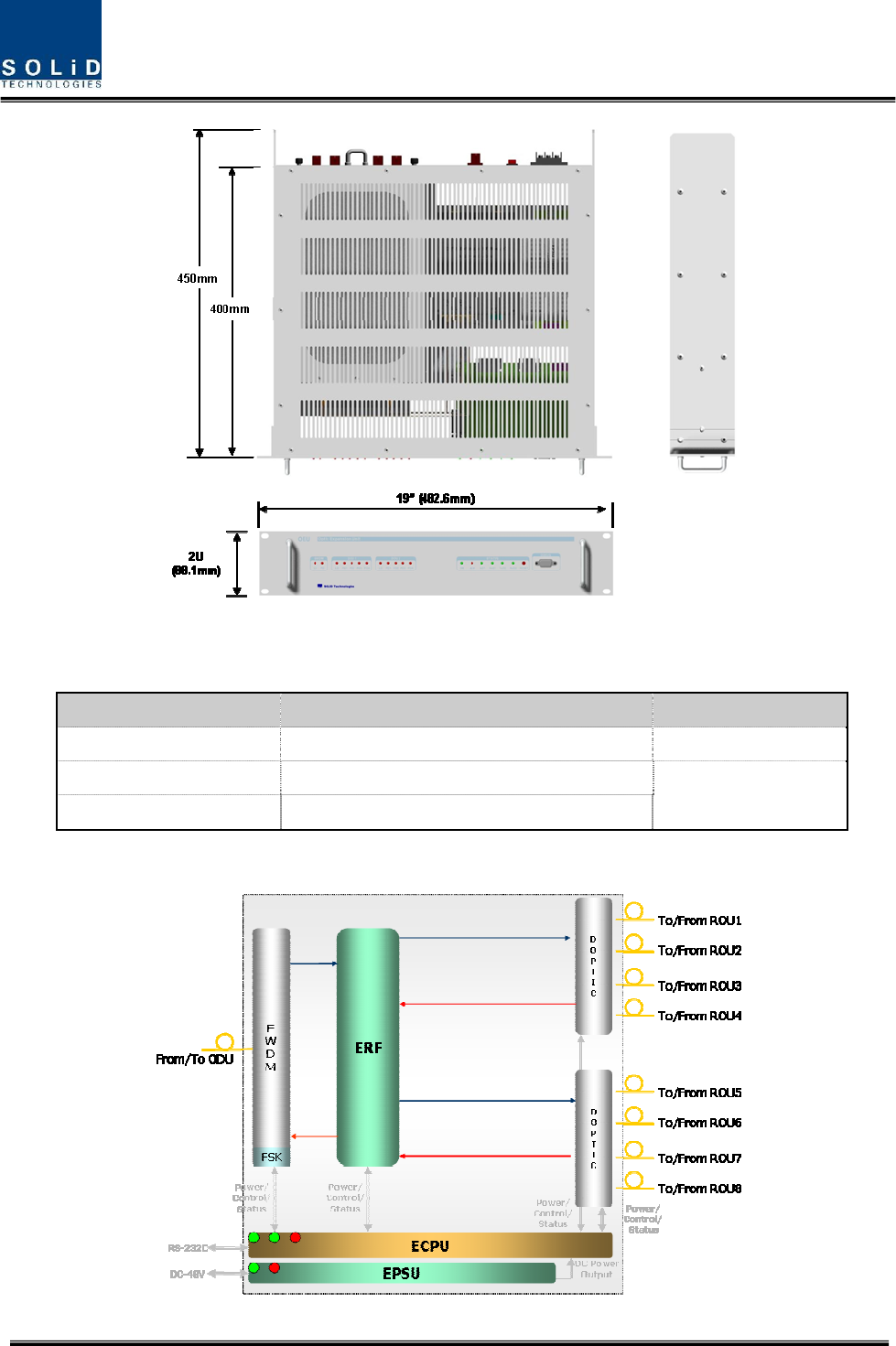
Figure 4.16 – OEU Outer Look
4.3.1 Specifications of OEU
Item Spec. Remark
Size 482.6(19”) x 88.1(2U) x 450 mm
Weight 9.3 Kg Full Load
Power consumption 48 W
4.3.2 Block Diagram of OEU
Confidential & Proprietary 42/136
4.3.3 OEU parts
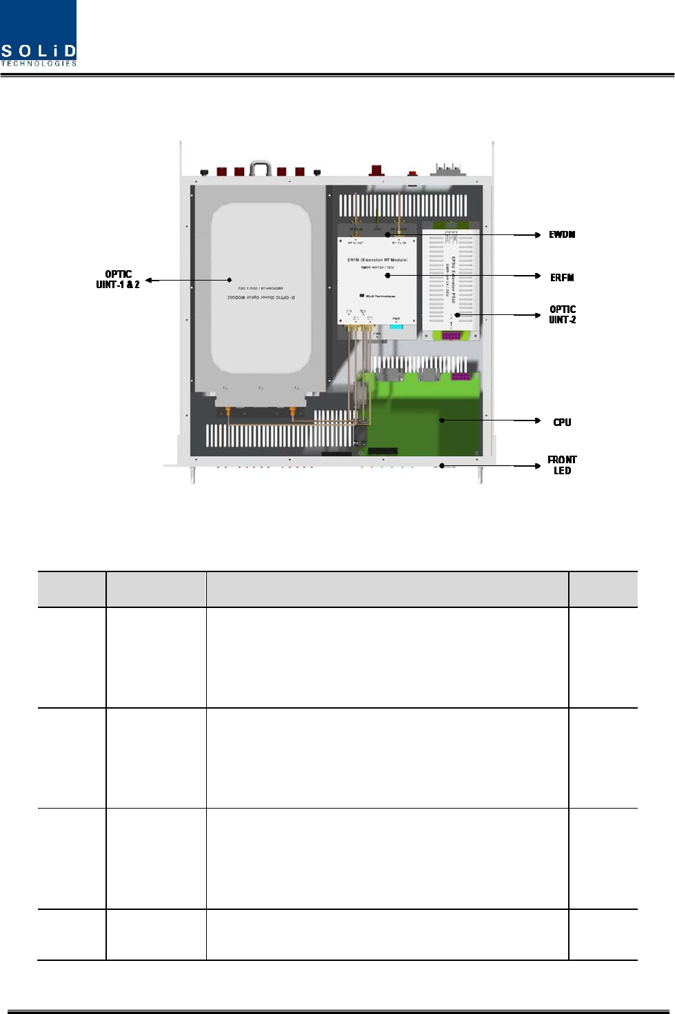
Figure 4.17 – OEU Inner Look
No. Unit Description Remark
1 DOU
Donor Optic Unit
Convert TX RF signals into optical signals;
Convert RX optical signals into RF signals;
Provide up to four optical ports per DOU
Max 2ea
2 EWDM
Expansion Wavelength Division Multiplexer
Convert TX optical signals into RF signals;
Convert RX RF signals into optical signals;
Compensate for optical cable loss with ODU
3 ECPU
Expansion Central Processor Unit
Control and monitoring system status
Control and monitoring with RS232
Relay state values of ROU to BIU
4 EPSU Expansion Power Supply Unit
Input power: DC -48V, Output power: 9V, 6V
Confidential & Proprietary 43/136
5 ERFM
Expansion Radio Frequency Module
Regenerate TX signals and transmit FSK modem
signals;
Regenerate RX signals and receive FSK modem signals
6 Shelf 19” rack, 2U
4.3.4 Function by unit
1) Donor Optic Unit (DOU)
DOU is the same as the module used for ODU.
Figure 4.18 – MDBU Outer Look
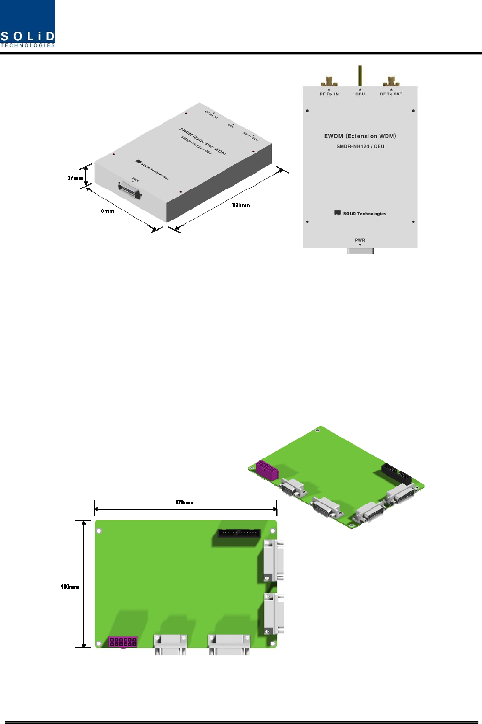
2) Expansion Wavelength Division Multiplexer(EWDM)
EWDM module makes optical-electronic conversion of TX signals and makes electronic-optical
conversion of RX signals. With an FSK modem in it, this multiplexer communicates with BIU. It
also has ATT for optical compensation to compensate for optical cable loss between ODUs.
Furthermore, it has internal WDM, and so, it needs only one optical cable to work with ROU.
Confidential & Proprietary 44/136
Figure 4.19 – EWDM Outer Look
3) Expansion Central Processor Unit(ECPU)
ECPU can inquire and control state of modules to be installed into OEU. This unit
communicates with upper BIU while communicating with lower ROU. It also acts as
communication bridge between BIU and ROU.
In addition, the unit has RS-232C port for serial communication, which enables inquiry and
control of devices thorugh PC. At the front panel, communication LED indicator indicates
communication state with upper BIU and lower ROU. It also has ALM LED indicator to show if a
device gets faulty.
Figure 4.20 – ECPU Outer Look
4) Expansion Radio Frequency Module(ERFM)
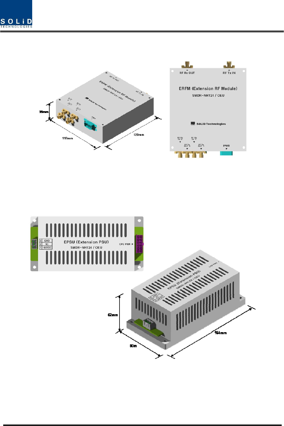
Confidential & Proprietary 45/136
ERFM reconstructs Signal to Noise degraded by optical modules. With an internal FSK modem,
this module communicates with ROU.
Figure 4.21 – ERFM Outer Look
5) Expansion Power Supply Unit(EPSU)
As DC/DC Converter, EPSU receives -48V of input and provides +9V and +6V of DC power
required for OEU.
Figure 4.22 – ERFM Outer Look