SOLiD HM70P80P RDU (Remote Drive Unit) User Manual MB DAS
SOLiD, Inc. RDU (Remote Drive Unit) MB DAS
SOLiD >
User Manual
Confidential & Proprietary 1/39
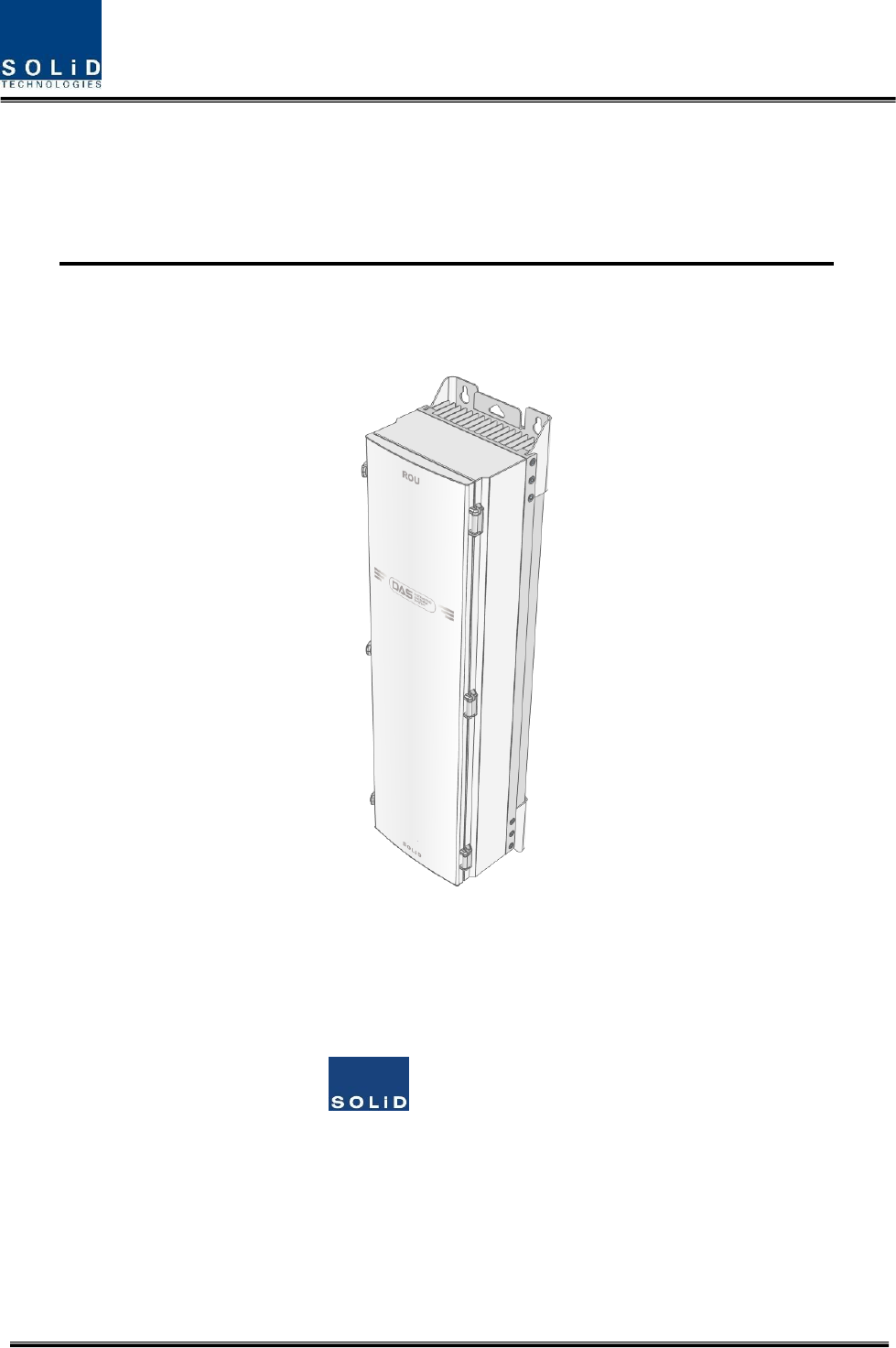
HERCULES (Alliance 5W Remote Unit)
User Manual
SOLiD, Inc.
10,9th Floor, SOLiD Space220 Pangyoyeok-ro, Bundang-gu, Seongnam-si, Gyeonggi-do, Korea 393-400
Tel : +82-31-627-6290 Fax : +82-31-627-6209
Confidential & Proprietary 2/39
REVISION HISTORY
Version
Issue Date
No. of Pages
Initials
Details of Revision Changes
V 1.0
September. 07, 2014
Original
Technical Support
SOLiD serial numbers must be available to authorize technical support and/or to establish a return
authorization for defective units. The serial numbers are located on the back of the unit, as well as on
the box in which they were delivered. Additional support information may be obtained by accessing the
SOLiD Tehcnology, Inc. website at www.solid.co.kr or send email at
kehan@solid.co.kr
This manual is produced by Global Business Division Business Team 1. Printed in Korea.

Confidential & Proprietary 3/39
Contents
Section1 Safety & Certification Notice ....................................................................... 5
Section2 Introduction ............................................................................................... 9
2.1 Purpose ......................................................................................................... 10
2.2 HERCULES ...................................................................................................... 11
Section3 Functional Description .............................................................................. 12
3.1 General ......................................................................................................... 13
3.2 Component of HERCULES Remote Unit ............................................................. 14
3.3 Dimension ..................................................................................................... 16
Section4 System Installation ................................................................................... 17
4.1 Remote Unit Installation ................................................................................. 19
4.1.1 Remote Unit Enclosure installation .................................................................. 19
4.1.2 How to expand ADD ON ROU at the Remote Unit .............................................. 23
4.1.3 Remote Unit Power Cabling ............................................................................. 25
4.1.4 Remote Unit Ground cabling ........................................................................... 26
4.1.5 Optical Cabling ............................................................................................... 28
4.1.6 Mounting of MRDU ........................................................................................ 30
Section5 System Specifications ................................................................................ 35
5.1 Physical Specifications .................................................................................... 36
5.2 RF performance .............................................................................................. 37
5.3 Certification ................................................................................................... 38

Confidential & Proprietary 4/39
Contents of Figure
Figure 3.1 – Remote Unit Block Diagram ............................................................ 13
Figure 3.2 – Inside of Remote Unit .................................................................... 14
Figure 3.3 – Remote Unit Dimension ................................................................. 16
Figure 4.1 – Exterior of Remote Unit .................................................................. 19
Figure 4.2 – Dimension used to install REMOTE UNIT on the WALL ........................ 20
Figure 4.3 – Procedures of installation ............................................................... 21
Figure 4.5 – Connection diagram between Remote Unit and ADD ON ROU (DC type)
.............................................................................................................. 24
Figure 4.6 – Location of Ground Terminal ........................................................... 26
Figure 4.7 – Information of Terminal .................................................................. 26
Figure 4.8 – How to install Ground Terminal ....................................................... 27
Figure 4.9 – Location of Optical Connector ......................................................... 28
Figure 4.10 – Information of Optical Connector .................................................. 28
Figure 4.11 – How to install Optical Cabling ........................................................ 29
Figure 4.12 – Location of MRDU ........................................................................ 30
Figure 4.13 – How to mount MRDU ................................................................... 31
Figure 4.14 – How to mount FAN Unit ................................................................ 32
Figure 4.15 – How to mount FAN Unit ................................................................ 33

Confidential & Proprietary 5/39
Section1
Safety & Certification Notice

Confidential & Proprietary 6/39
“Only qualified personnel should handle the DAS equipment. Any person involved in
installation or service of the DAS should understand and follow these safety guidelines.”
- Obey all general and regional safety regulations relating to work on high voltage installations, as well as
regulations covering correct use of tools and personal protective equipment.
- The power supply unit in repeaters contains dangerous voltage level, which can cause electric shock.
Switch the mains off prior to any work in such a repeater. Any local regulations are to be followed
when servicing repeaters.
- To prevent electrical shock, switch the main power supply off prior to working with the DAS System or
Fiber BDA. Never install or use electrical equipment in a wet location or during a lightning storm.
- When working with units outdoors, make sure to securely fasten the door or cover in an open position
to prevent the door from slamming shut in windy conditions.
- Use this unit only for the purpose specified by the manufacturer. Do not modify or fit any spare parts
that are not sold or recommended by the manufacturer. This could cause fires, electric shock or other
injuries.
- Any DAS system or Fiber BDA will generate radio (RF) signals and continuously emit RF energy. Avoid
prolonged exposure to the antennas. SOLiD recommends maintaining a 300cm minimum clearance
from the antenna while the system is operating.
- Do not operate this unit on or close to flammable materials, as the unit may reach high temperatures
due to power dissipation.
- Do not use any solvents, chemicals, or cleaning solutions containing alcohol, ammonia, or abrasives on
the DAS equipment. Alcohol may be used to clean fiber optic cabling ends and connectors.
- Do not look into the ends of any optical fiber or directly into the optical transceiver of any digital unit.
Use an optical spectrum analyzer to verify active fibers. Place a protective cap over any radiating
transceiver or optical fiber connector to avoid the potential of radiation exposure.
- Allow sufficient fiber length to permit routing without severe bends.
- For pluggable equipment, make sure to install the socket outlet near the equipment so that it is easily
accessible.
- Certification
FCC: This equipment complies with the applicable sections of Title 47 CFR Parts 15,22,24 and 90
UL/CUL: This equipment complies with UL and CUL 1950-1 Standard for safety for information
technology equipment,including electrical business equipment
FDA/CDRH: This equipment uses a Class 1 LASER according to FDA/CDRH Rules.This product
conforms to all applicable standards of 21 CFR Chapter 1, Subchaper J, Part 1040

Confidential & Proprietary 7/39
- A readyily accessible disconnect device shall be incorporated external to the equipment.
- This power of this system shall be supplied through wiring installed in a normal building.
If powered directly from the mains distribution system, it shall be used additional protection, such as
overvoltage protection device
- Only 50 ohm rated antennas, cables and passive equipment shall be used with this remote. Any
equipment attached to this device not meeting this standard may cause degradation and unwanted
signals in the bi-directional system. All components connected to this device must operate in the
frequency range of this device.
- Only 50 ohm rated antennas, cables and passive components operating from 150 - 3 GHz shall be used
with this device.
- The head end unit must always be connected to the Base Station using a direct cabled connection.
This system has not been approved for use with a wireless connection via server antenna to the base
station.
- Round terminals located on the side of a 1 mm2 (16 AWG) or more wires Using permanently
connected to earth.(green/yellow color)
- The following notice: "The Manufacturer's rated output power of this equipment is for single carrier
operation. For situations when multiple carrier signals are present, the rating would have to be reduced
by 3.5 dB, especially where the output signal is re-radiated and can cause interference to adjacent band
users. This power reduction is to be by means of input power or gain reduction and not by an attenuator
at the output of the device."
- Part 90.635 requirement
Antennas must be installed in accordance with FCC 90.635. With 17 dBi gain antennas the height of the
antenna above average terrain (HAAT) must not exceed 763 m. For different gain antennas refer to the
relevant rules.
- Prior to equipment use the service must be registered with the FCC. This can be done through the
FCC’s website at https://signalboosters.fcc.gov/signal-boosters/.
Confidential & Proprietary 8/39
- Access can only be gained by SERVICE PERSONS or by USERS who have been instructed about the
reasons for the restrictions applied to the location and about any precautions that shall be taken; and
- Access is through the use of a TOOL or lock and key, or other means of security, and is on trolled by the
authority responsible for the location.
- Maximum antenna gain for downlink antenna after accounting for any cable losses should be less than
2 dBi.
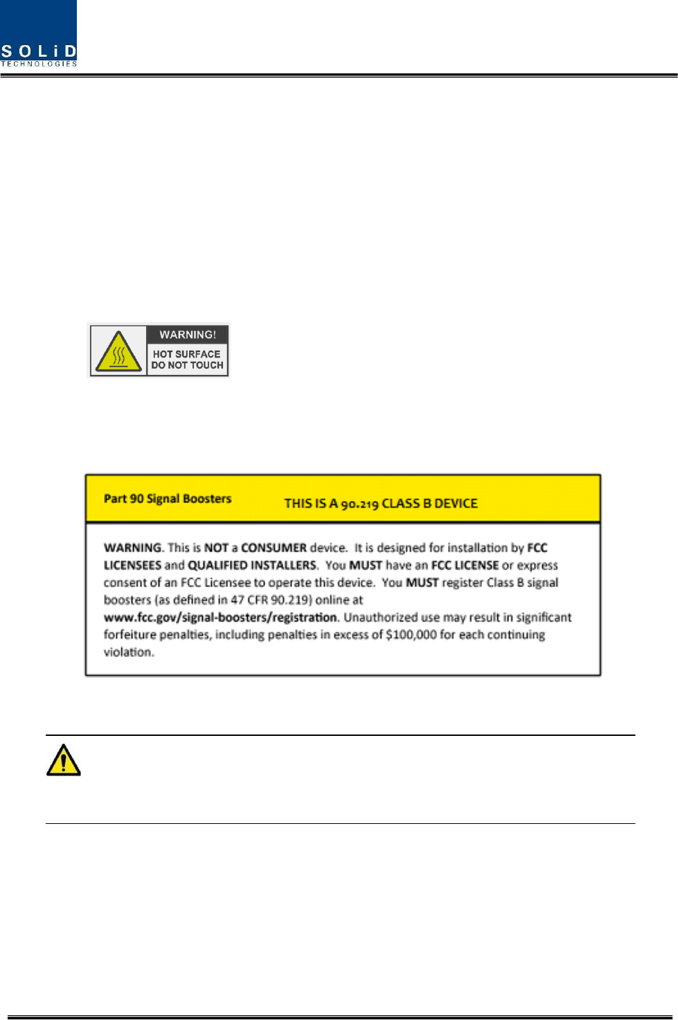
- Notice! Be careful not to touch the Heat-sink part due to high temperature.
- Signal booster warning label message should include (Class B Industrial Booster)
CAUTION
DOUBLE POLE/NEUTRAL FUSING

Confidential & Proprietary 9/39
Section2
Introduction
2.1 Purpose
2.2 HERCULES

Confidential & Proprietary 10/39
2.1 Purpose
HERCULES is a coverage system for in-building services delivering voice and data in high quality and for
seamlessly.
As a distributed antenna system, it provides analog and digital phone systems that are served in multiple
bands through one antenna.
The system covers general public institutions and private facilities.
Shopping malls
Hotels
Campus areas
Airports
Clinics
Subways
Multi-use stadiums, convention centers, etc.
The system helps improve in-building radio environments in poor condition and make better poor RSSI
and Ec/Io. By providing communication services at every corner of buildings, the system enables users to
make a call at any site of buildings.
The system uses both analog (AMPS) and digital (TDMA, CDMA and WCDMA) methods.
The HERCULES system supports communication standards and public interface protocols in worldwide
use.
Frequencies: 700MHz , 700MHz_MIMO , 850MHz , 1900MHz , 2100MHz , 2100MHz_MIMO
etc.
Voice protocols: AMPS,TDMA, CDMA,GSM,IDEN, etc.
Data protocols: EDGE,GPRS,WCDMA,CDMA2000,Paging, LTE etc.
HERCULES is in modular structure per frequency. To provide desired frequency in a building, all you
need to do is to insert a corresponding frequency module into each unit. As it delivers multiple signals
with one optical cable, the system, in one-body type, does not require additional facilities whenever
new frequency is added.
The system is featured with the following:
Flexibility & Scalability
Support fiber-optic ports up to 60
Clustering multiple-buildings (campus) as one coverage
Modular structures
Modular frequency upgrade
Plug-in type module

Confidential & Proprietary 11/39
Multi-Band, Multi Operator
Signals with a plurality of service provider transmit simultaneously
Support multi-operator in a band
Low OPEX / CAPEX
Compact design
Upgradable design
Easy installation and maintenance
2.2 HERCULES
Hercules is one of series of Alliance DAS and has 5W composite output power every band.
RDU that is integrated on package with Duplexer, Power amplifier and RF unit can be mounted up to 6 in
the enclosure.
Hercules transports signals that multiple operators and multiple technologies are moved at a same time
from Base station to a remote location over the same fiber.
It is available in single and multi-band configuration supporting 700M, 700M MIMO , 850M , 800I , 900I ,
700P , 800P , 1700/2100M, 1700/2100MHz MIMO , 1900M in parallel.
It has been specifically tested under a various air interfaces such as iDEN, GSM, CDMA2000, EV-DO,
WCDMA, LTE , ect.
Furthermore, there is reserved RDU slot to support 2500LTE in the future
And RDU slot is also possible to replace the desired frequency Band.

Confidential & Proprietary 12/39
Section3
Functional Description
3.1 General
3.2 Compoent of HERCULES Remote Unit
3.3 Dimension
Confidential & Proprietary 13/39
3.1 General
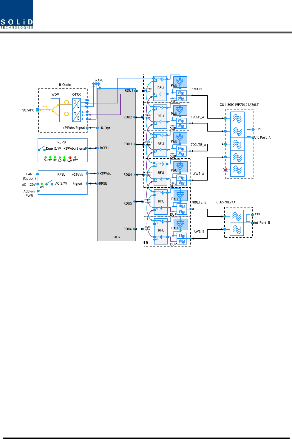
The following figure shows the block diagram of HERCULES Remote Unit.
Figure 3.1 – Remote Unit Block Diagram
There are many components;
R-Optic : Remote Optical Unit
RCPU : Remote Central Processor Unit
RPSU(AC) : Remote AC Power Supply Unit(When using the AC input power)
RPSU(DC) : Remote DC Power Supply Unit(When using the DC input power)
RDU1-6 : Remote Drive Unit
CU1 : Combining Unit
CU2 : Combining Unit
Confidential & Proprietary 14/39
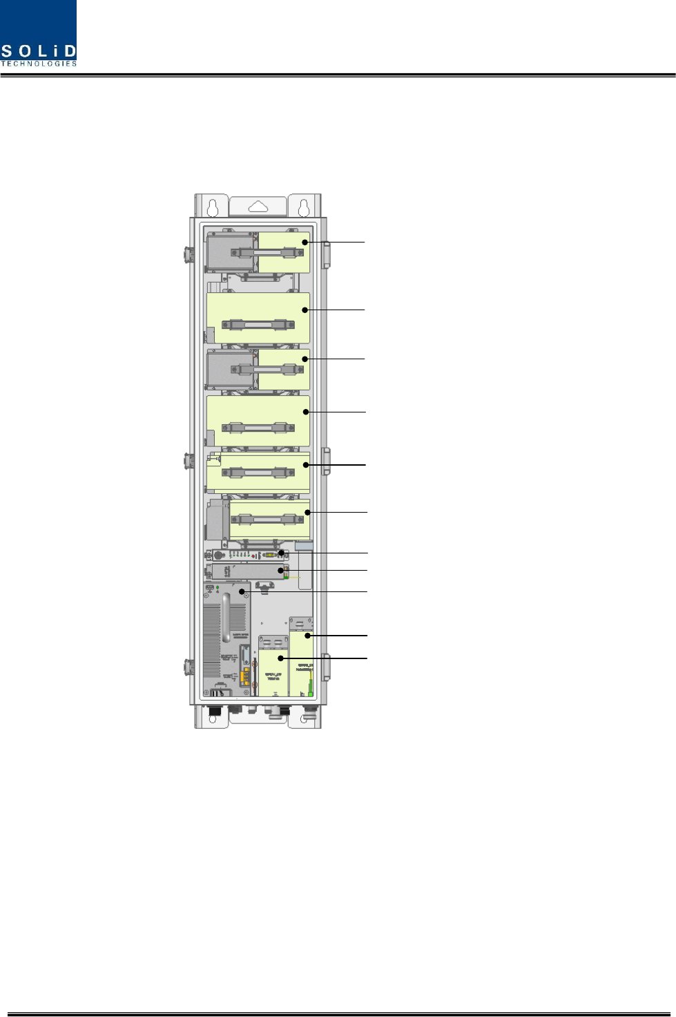
3.2 Component of HERCULES Remote Unit
The following figure shows internal configuration of Remoe Unit with fully RF equipped.
2100AWS-1_MIMO RDU
700LTE_MIMO RDU
2100AWS-1 RDU
700LTE RDU
1900PCS RDU
850CEL RDU
RCPU
R-Optic
R-PSU(AC or DC)
CU1 (Multiplexer)
CU2 (Multiplexer)
Figure 3.2 – Inside of Remote Unit
Remote Unit receives TX optical signals from Head-End and converts them into RF signals. The converted
RF signals are amplified through High Power Amp in a corresponding RDU, combined with Multiplexer
module and then radiated to the antenna port.
When receiving RX signals through the antenna port, this unit filters out-of-band signals in a
corresponding RDU and sends the results to Remote Optic Module to make electronic-optical
conversion of them. After converted, the signals are sent to a upper device of ODU. ROU can be
equipped with up to six RDUs (Remote Drive Unit)

Confidential & Proprietary 15/39
The following table describes components on Remote Unit
Unit
Description
RDU+BPF x6
Remote Drive Unit
Filter and amplify TX signals
Filter and amplify RX signals
Remove other signals through BPF
RPSU(AC)
Remote AC Power Supply Unit
Input power: 120 VAC +/- 10%
Output power: +29 VDC
RPSU(DC)
Remote DC Power Supply Unit
Input power: -48 VDC +/- 10%
Output power: +29 VDC
R-OPTIC
Remote Optic
Make RF conversion of TX optical signals;
Convert RX RF signals into optical signals; Compensates optical loss
Communicates with BIU/OEU though the FSK modem
5dBo optical link between ODU(OM4) and ROU
10dBo optical link between ODU(OM1) and ROU
Fiber Connector: SC/APC Connector
Fiber Type: Single Mode Fiber
Optical Wavelength: 1310/1550 WDM
RCPU
Remote Central Processor Unit
Controls signal of each unit
Monitors BIU/ODU/OEU through FSK communication
CU1(Multiplexer)
CU1
Combine TX signals from 5 RDUs; Distribute RX signals to 5 RDUs
Furthermore, there is reserved RDU slot to support 2600LTE
Enable you to use a single antenna port
CU2(Multiplexer)
CU2
Combine TX signals from 2 RDUs; Distribute RX signals to 2 RDUs
Enable you to use a single antenna port
ROU Enclosure
Enclosure to satisfy IP66
Vertical Mount
Wall Mount
Input SIU
Input System Interface Unit
Distributes power and signals to each module
Output SIU
Output System Interface Unit
Interfacing with multiplexer
Confidential & Proprietary 16/39
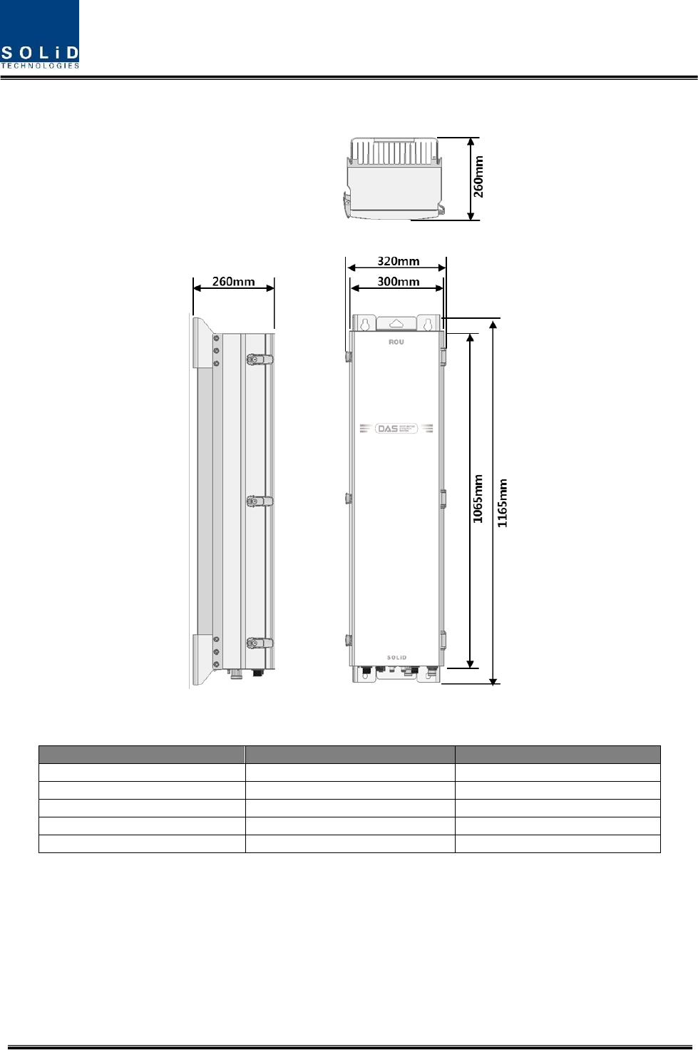
3.3 Dimension
Figure 3.3 – Remote Unit Dimension
ITEM
SPECIFICATION
REMARK
Size(Width, Height, Depth)
320 x 1165 x 260mm
Including Bracket
Weight
62kg / 137lb
Fully loaded
Power Consumption
510W
Fully loaded
Operating Temperature
-25 to +55°C / -13 to 131°F
Ambient Temperature
Operating Humidity
0 to 90%, non-condensing

Confidential & Proprietary 17/39
Section4 System
Installation
5.1 Remote Unit Installation
This chapter describes how to install each unit and optical cables, along with power cabling method. In
detail, the chapter describes how to install shelves or enclosures of each unit, Power Cabling method
and Optic Cabling and RF Interface.
The needed accessories and tools are list up in the below table.
Steps for
installation
Accessories
Included
Tool
Remark
Remote
Enclosure
Installation
M12 Bolt (4EA)
X
Spanner(19mm)
-
Power
Connection_AC
AC 120V power cable (1EA)
[2 meter, with MIL-5015 type Connector (MS-
3106A- 18-10S) at one end, AC Plug at another
end]
○
-
-
Power
Connection_DC
DC -48V power cable (1EA)
[2 meter, with MIL-5015 type Connector (MS-
3106A- 18-10S) at one end, 4.5 ø square lugs
at another end]
○
-
-
Optical
Connection
Optical Cable Assembly Connector (1EA)
[SOLI-FIBER-ASS’Y, by LTW]
○
-
For more
details,

Confidential & Proprietary 18/39
OPTIC SC/APC Cable (1EA)
X
-
refer to
4.1.5
Ground
Connection
M6 Screw (1EA)
○
No.2 Screw driver (+)
For more
details,
refer to
4.1.4
Lug (1EA)
○
Crimping Tool
Max. AWG #6 Cable
X
Antennal
Connection
RF Cable (1 or 2EA)
X
Spanner (33mm)
2 EA is
required
in case of
MIMO.
MRDU
Installation
-
-
No.1 Screw driver (+)
For more
details,
refer to
4.1.6
Connection
with ADD ON
ROU
AC power cable (1 EA)
[1.5 meter, with MIL-5015 type Connector
(MS-3106A-16-10S) and Circular Connector
(C016_20H003_100_12, by LTW)]
○
-
-
Data Interface cable (1 EA)
[1.5 meter, with MIL-5015 type Connector
(MS-3106A-14S-5S) at both ends]
○
-
-
RF interface cable (2EA)
[1.5 meter, with N male connector at both
ends]
○
-
-
FAN Unit
(Option)
Inner Fan Cable
○
Spanner (10mm)-
For more
details,
refer to
4.1.7
Fan Unit
○
-
M6 Screw (1EA)
X
No.2 Screw driver (+)
Confidential & Proprietary 19/39
4.1 Remote Unit Installation
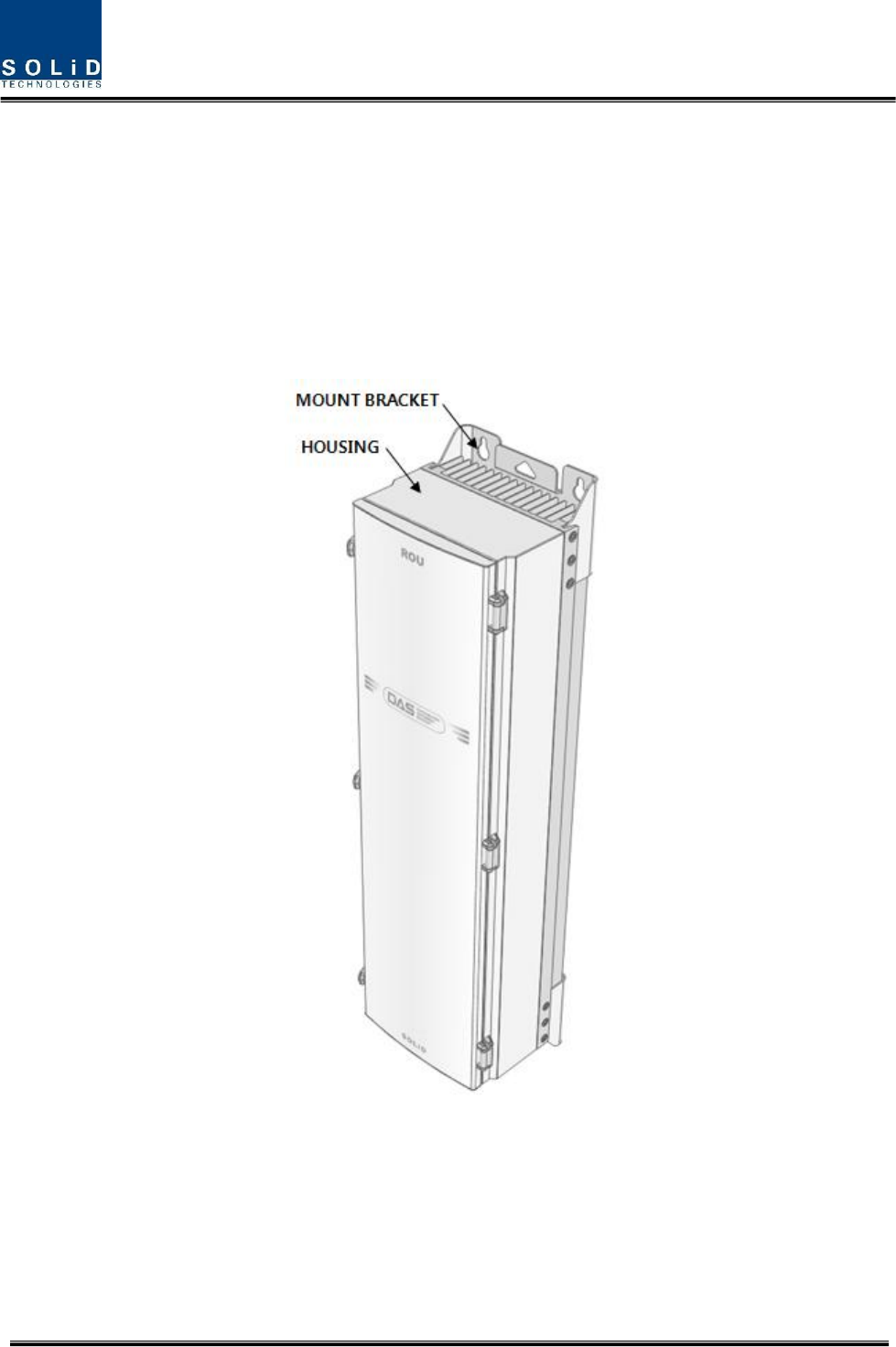
4.1.1 Remote Unit Enclosure installation
Remote Unit is designed to be water- and dirt-proof. The unit has the structure of one-Body enclosure.
It satisfies water-proof and quake-proof standards equivalent of NEMA4(IP66). Basically Remote Unit is
attached with wall mountable bracket. Remote Unit can be mounted into either of wall or on a pole.
Figure 4.1 – Exterior of Remote Unit
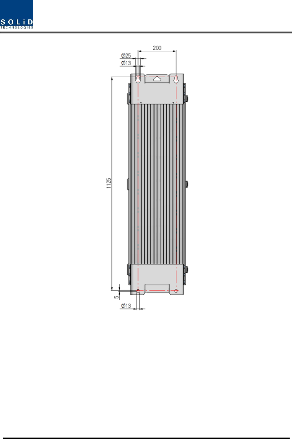
Confidential & Proprietary 20/39
Figure 4.2 – Dimension used to install REMOTE UNIT on the WALL
Confidential & Proprietary 21/39
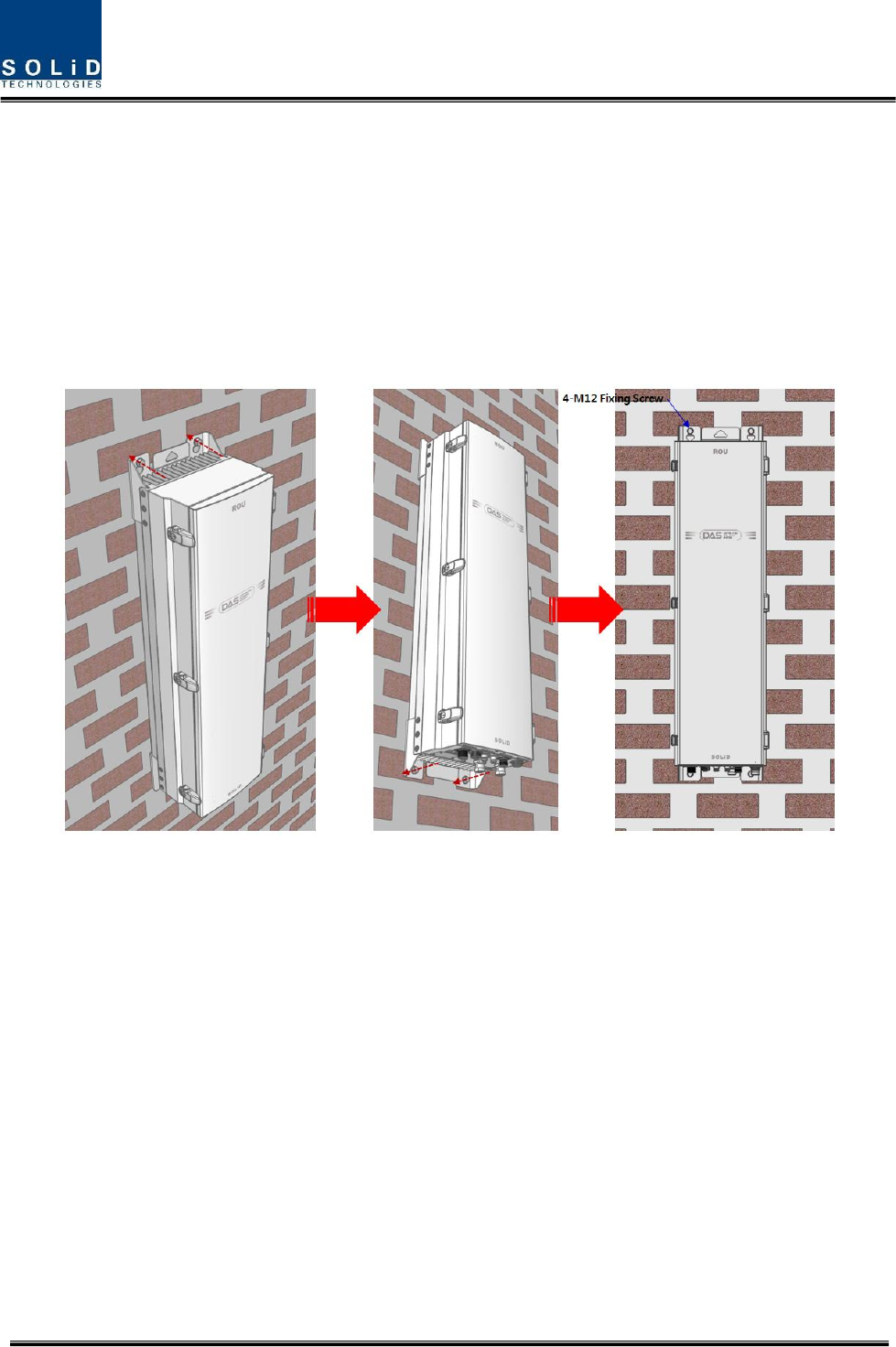
Remote Unit Wall Mount Installation
Remote Unit’s installation bracket is attached on Enclosure when is delivered. It doesn’t need to remove
bracket to install enclosure. simply after installing 4 of M12 mounting bolts, secure 4 mounting bolts
tightly
First, install 2 of M12 mounting bolts roughly half way on the enclosure and install enclosure over the
bolts and secure tightly.
Second, install 2 of M12 mounting bolts under the enclosure and secure tightly.
Figure 4.3 – Procedures of installation
Confidential & Proprietary 22/39
Remote Unit Components
Remote Unit has the following components:
No.
Unit
Description
Remark
Common Part
Enclosure
Including Wall mounting bracket
1EA
RCPU
-
1EA
R_OPTIC
With SC/ACP adaptor(only Remote Unit)
1EA,optional
RPSU
AC 120V or DC-48V
1EA
Power Cable
MS Connector with 4 hole
1EA
MRDU
MRDU-850CEL
MRDU-1900PCS
MRDU-700LTE
MRDU-2100AWS-1
MRDU-2500LTE(Reserved)
ANT1
MRDU
MRDU-700LTE_MIMO
MRDU-2100AWS-1_MIMO
ANT2
CU1
Internal Combiner unit for 700, 900,850, 1900, 2100,
and 2500(Reserved)
ANT1
CU2 or CU3
Internal Combiner unit for 700 and 2100 MIMO
Internal Combiner unit for 700P/800P and 900I
ANT2
Basically, the common part of Remote Unit should have an enclosure and it is equipped with RCPU to
inquire and control state of each module, R_OPTIC to make both of electronic-optical and optical-
electronic conversions, RPSU to supply power for Remote Unit. It should have Power Cable for external
rectifier or to supply required power.
In addition, MRDU can be mounted and removed to provide service for desired band.
Confidential & Proprietary 23/39
4.1.2 How to expand ADD ON ROU at the Remote Unit
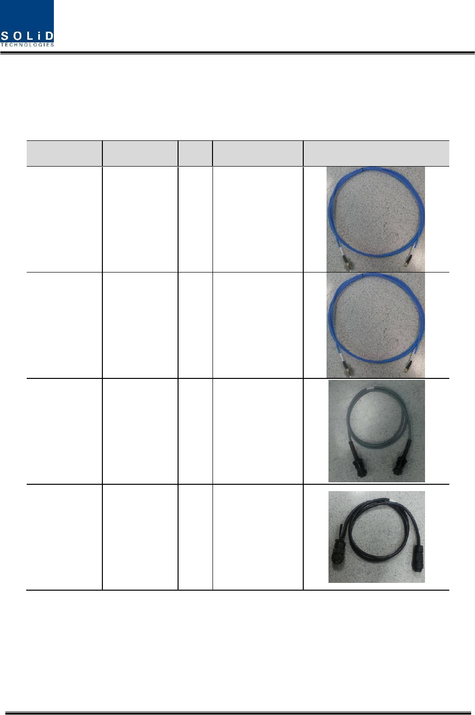
Remote Unit can expand ARU up to 1. The three item is needed for connection between Remote Unit
and ADD ON ROU. ADD ON ROU’s components additively have 3 item except for enclosure like below
Accessories
Description
Qty
Specification
Remark
1
TX RF Cable
1
N(M) ST to SMA(M)
ST_1.5M
2
RX RF Cable
1
N(M) ST to SMA(M)
ST_1.5M
3
I/O Cable
1
IEC 61076-2-
101(8pin_F)
ST_1.5m
4
Power Cable
(AC type only)
1
MIL-5015(16-10_F)
ST to Circular(eco
mate 3+PE_M)
ST_1.5m
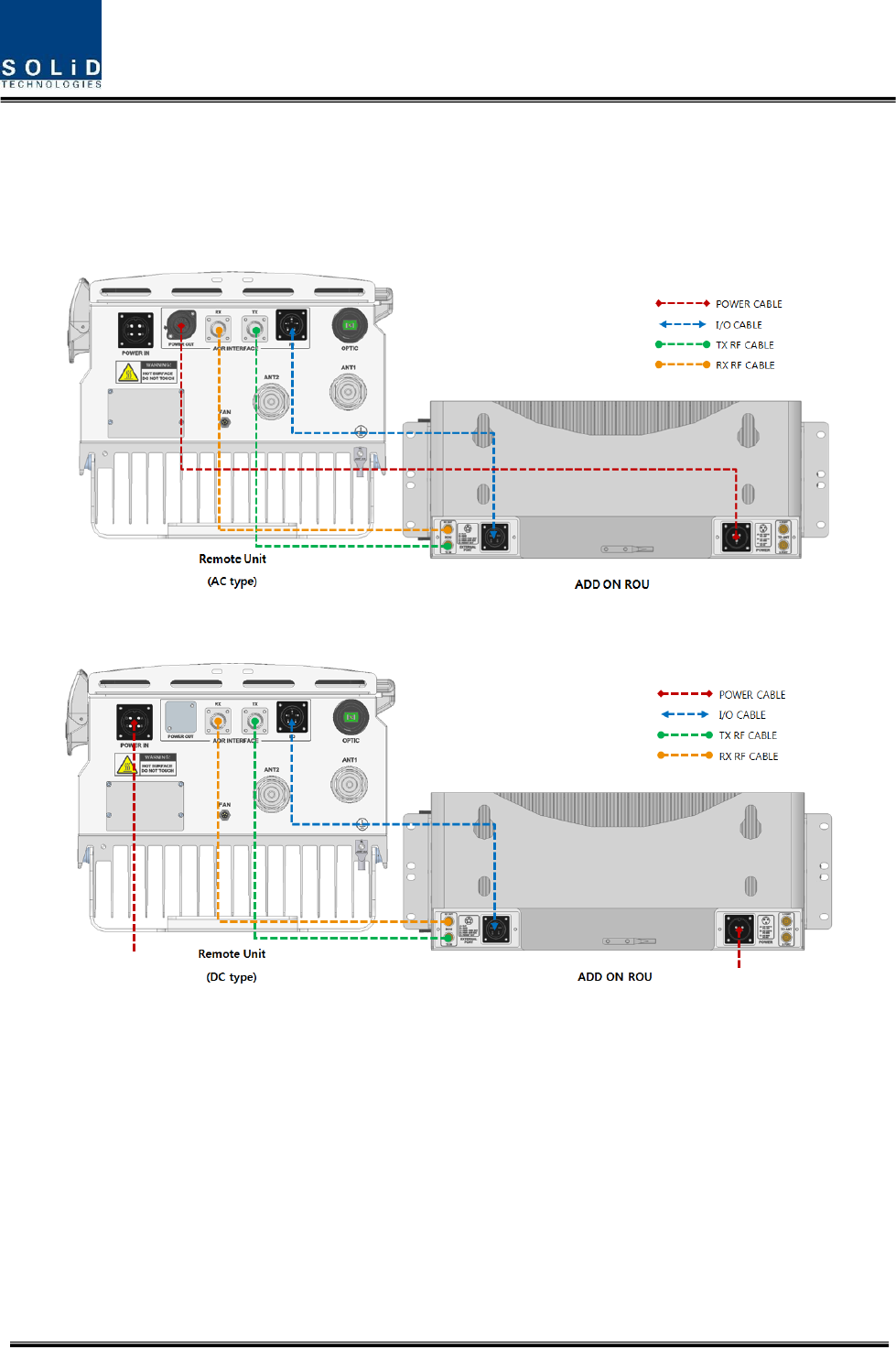
The following picture shows the connection diagram between Remote Unit and ADD ON ROUs
Confidential & Proprietary 24/39
For expanding ADD ON ROU at the Remote Unit within the proper cable length provided. The cables
between Remote Unit and ADD ON ROU have each 1.5m length.
Figure 4.4 – Connection diagram between Remote Unit and ADD ON ROU (AC type)
Figure 4.5 – Connection diagram between Remote Unit and ADD ON ROU (DC type)
Confidential & Proprietary 25/39
4.1.3 Remote Unit Power Cabling
AC Power
Remote Unit supports only AC120V of input power. Provided outside power cable is only one type.
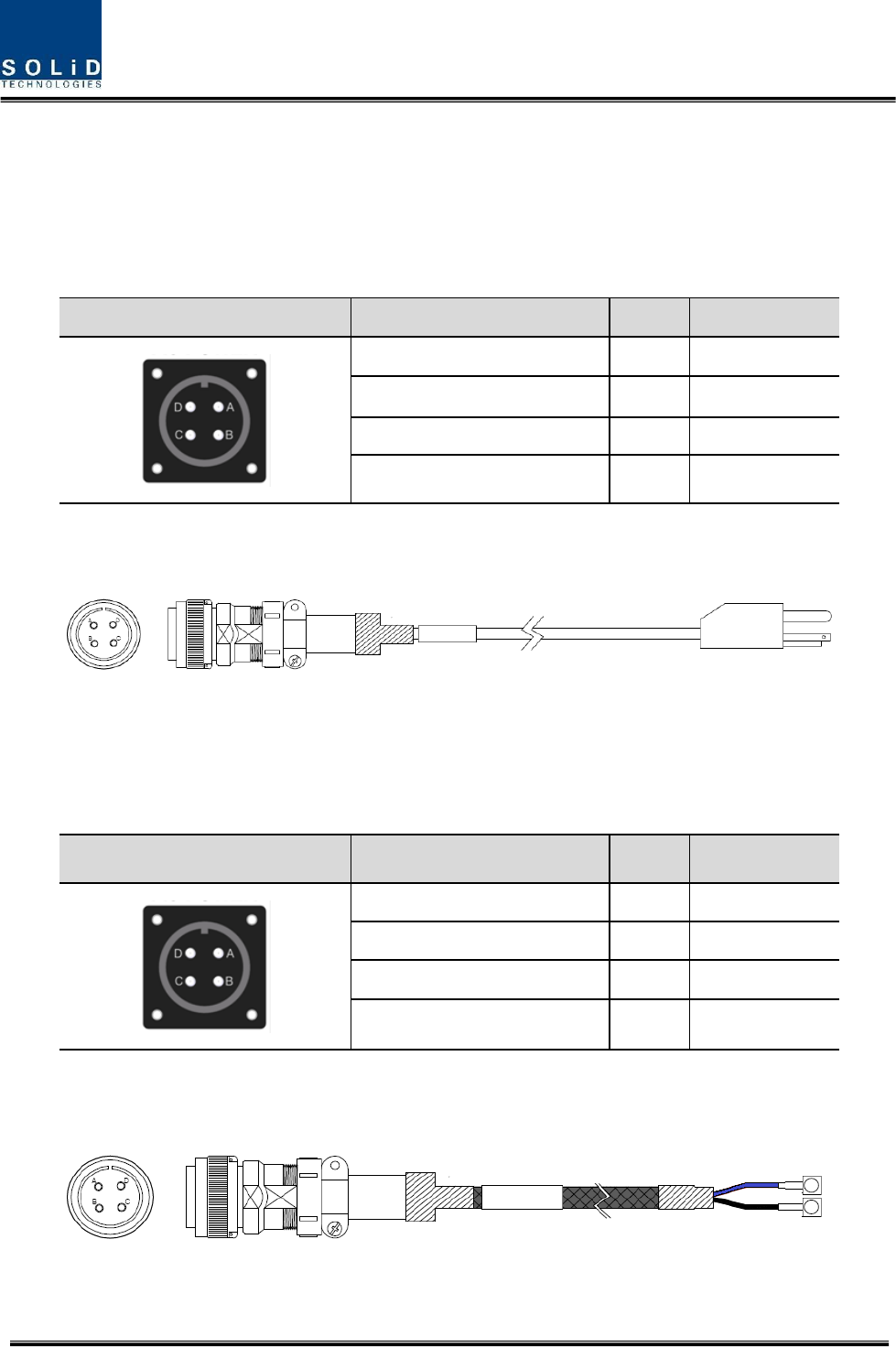
The pin discription of AC port is below. You should connect exact polarity of AC.
Port outlook
MS Connector numbering
Name
Description
A
AC_H
AC Hot
B
AC_N
AC Neutral
C
N.C
Not Connected
D
F.G
Frame Ground
Check if the connection is the same as one seen in the table above and make sure to turn the power ON.
Provided AC power cable’s outlook is below
DC Power
Remote Unit supports only DC48V of input power. Provided outside power cable is only one type.
The pin discription of DC port is below. You should connect exact polarity of DC.
Port outlook
MS Connector numbering
Name
Description
A
N.C
Not Connected
B
N.C
Not Connected
C
+V
+48V
D
-V
-48V
Check if the connection is the same as one seen in the table above and make sure to turn the power ON.
Provided DC power cable’s outlook is below
Confidential & Proprietary 26/39
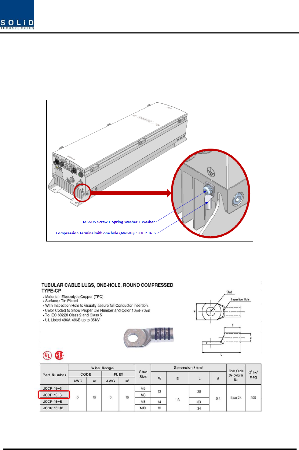
4.1.4 Remote Unit Ground cabling
The Grounding terminal is located at the bottom of Remote Unit enclosure fixed by M6 screw.
Compression terminal is attached already when is delivered. The recommended thickness of cable is
AWG#6 copper grounding wire
Figure 4.6 – Location of Ground Terminal
The specification of compression terminal is like below
Figure 4.7 – Information of Terminal
Confidential & Proprietary 27/39
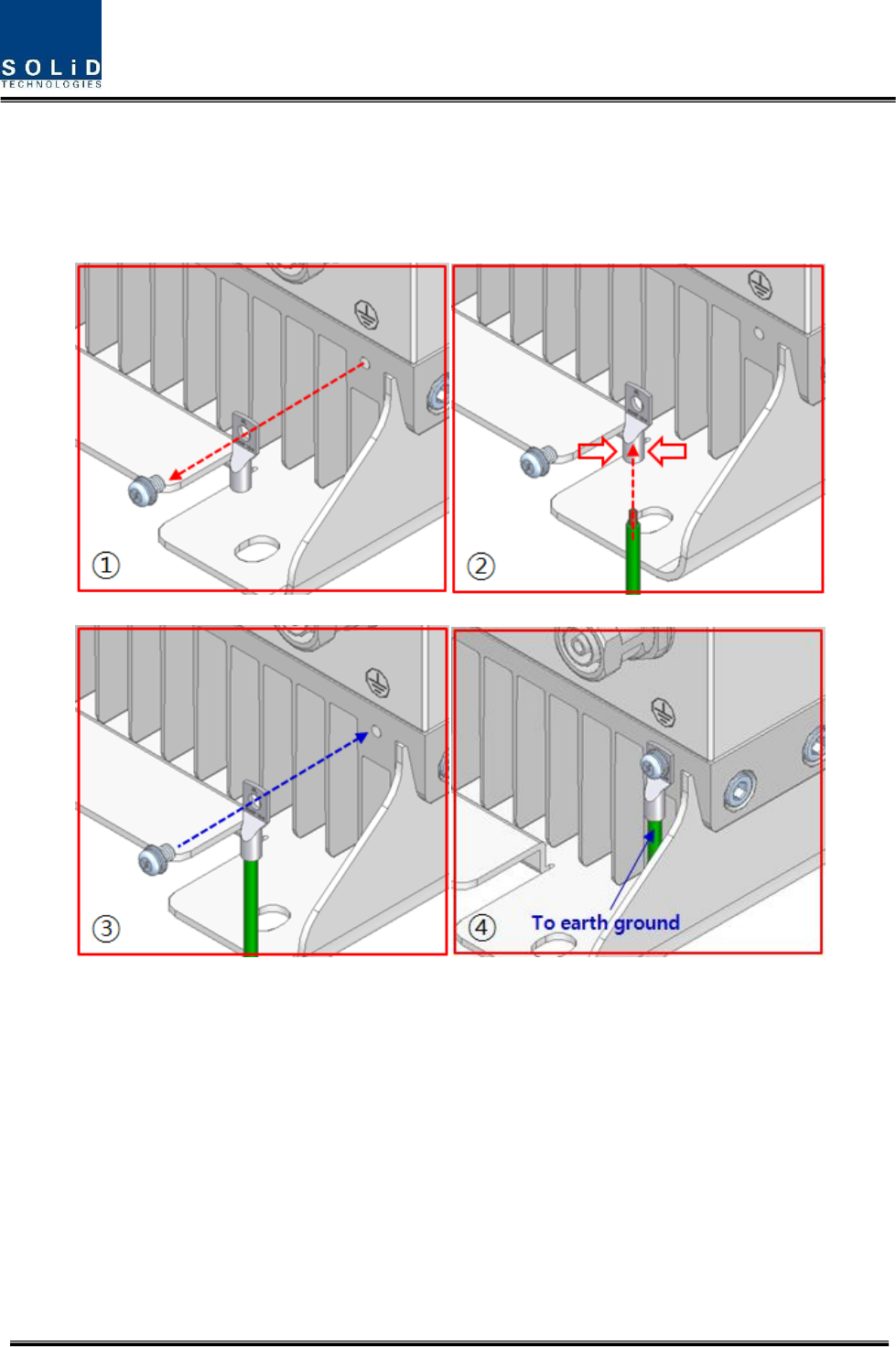
The required part number is JOCT 16-6 supporting AWG 6. The way to install the grounding cable
comply with below procedures
Figure 4.8 – How to install Ground Terminal
The procedures are
1. Loosen a two M6 screws and then take compression terminal off
2. Insert AWG#6 Grounding Wire into terminal and then compress a terminal using tool
3. Assemble the terminal which made in step “2” using 2xM6 screws
4. Cut the ground wire to proper length and connect it to the earth ground source
Confidential & Proprietary 28/39
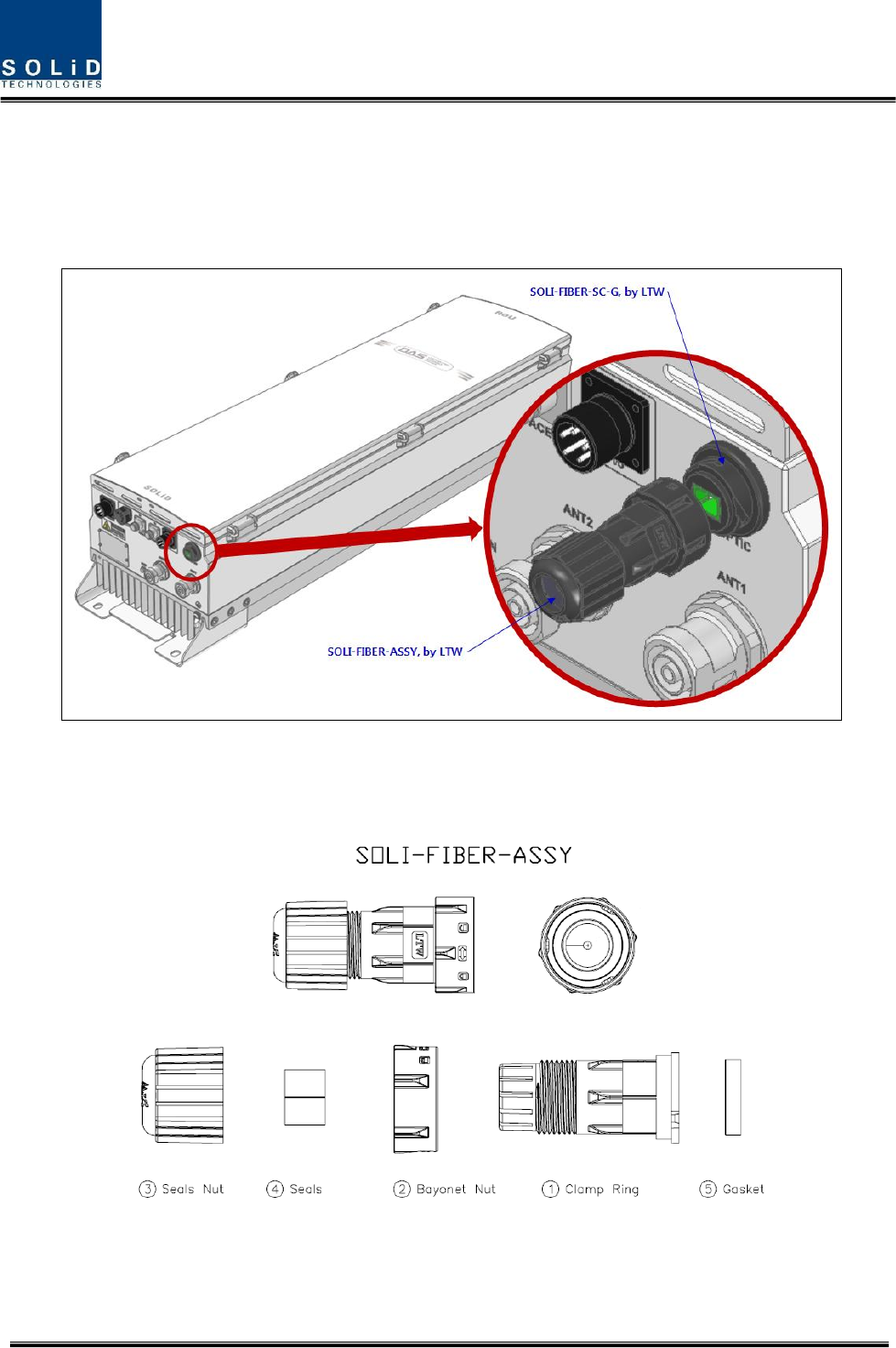
4.1.5 Optical Cabling
The Optical Connector is located at the bottom of Remote Unit enclosure fixed. Optical Cable can be
connected by using connectors.
Figure 4.9 – Location of Optical Connector
The specification of compression Optic Connector is like below
Figure 4.10 – Information of Optical Connector
Confidential & Proprietary 29/39
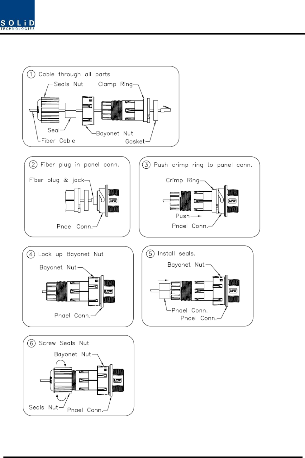
The way to install the Optical cable comply with below procedures
The procedures are
Figure 4.11 – How to install Optical Cabling
Confidential & Proprietary 30/39
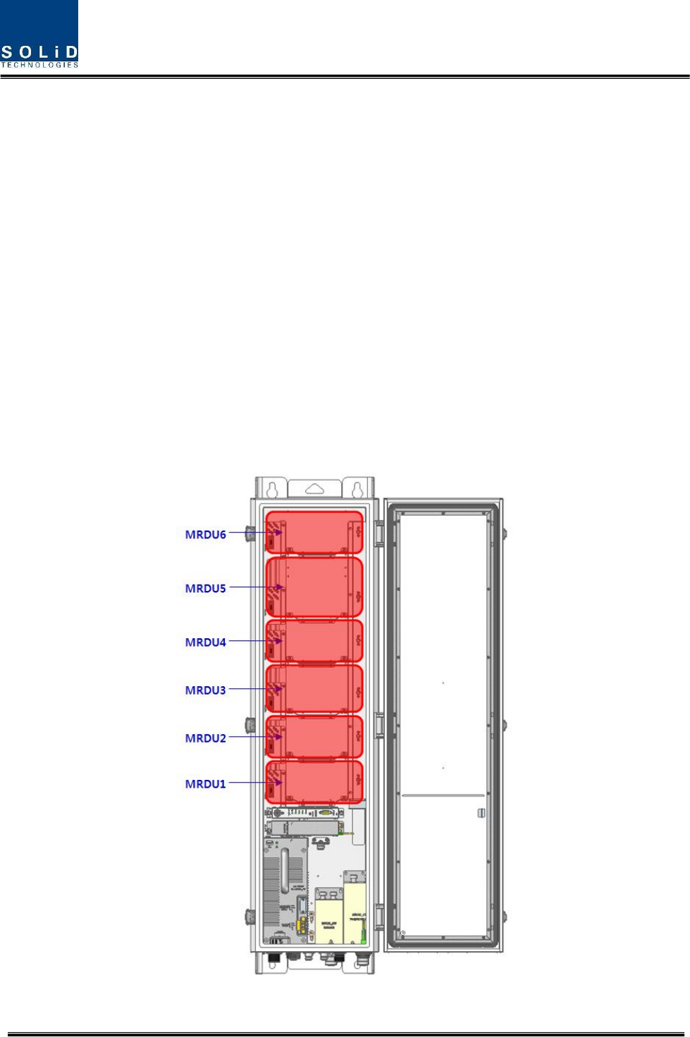
4.1.6 Mounting of MRDU
Remote Unit has slots to enable up to six MRDU modules to be mounted in it.
You can mount a MRDU into designated slot surely. It is not possible to provide services with a
MRDU module alone; you need to connect MRDU cavity duplexer antenna port with CU’s
designated port.
Installation Diagram for MROU Module Assembly
1) Install each MRDU into its designated location as shown in the graphic.
2) If MRDUs are inserted in slot #5 or #6, install the optional combiner unit (CU) according to
these guidelines:
Option 1: CU_70B21B
Use this unit for combining MRDU_700LTEF_B / MRDU_AWS_B
Option 2 : CU_708090
Use this unit to combine MRDU_700PS_800PS / MRDU_900i
Figure 4.12 Location of MRDU
Confidential & Proprietary 31/39
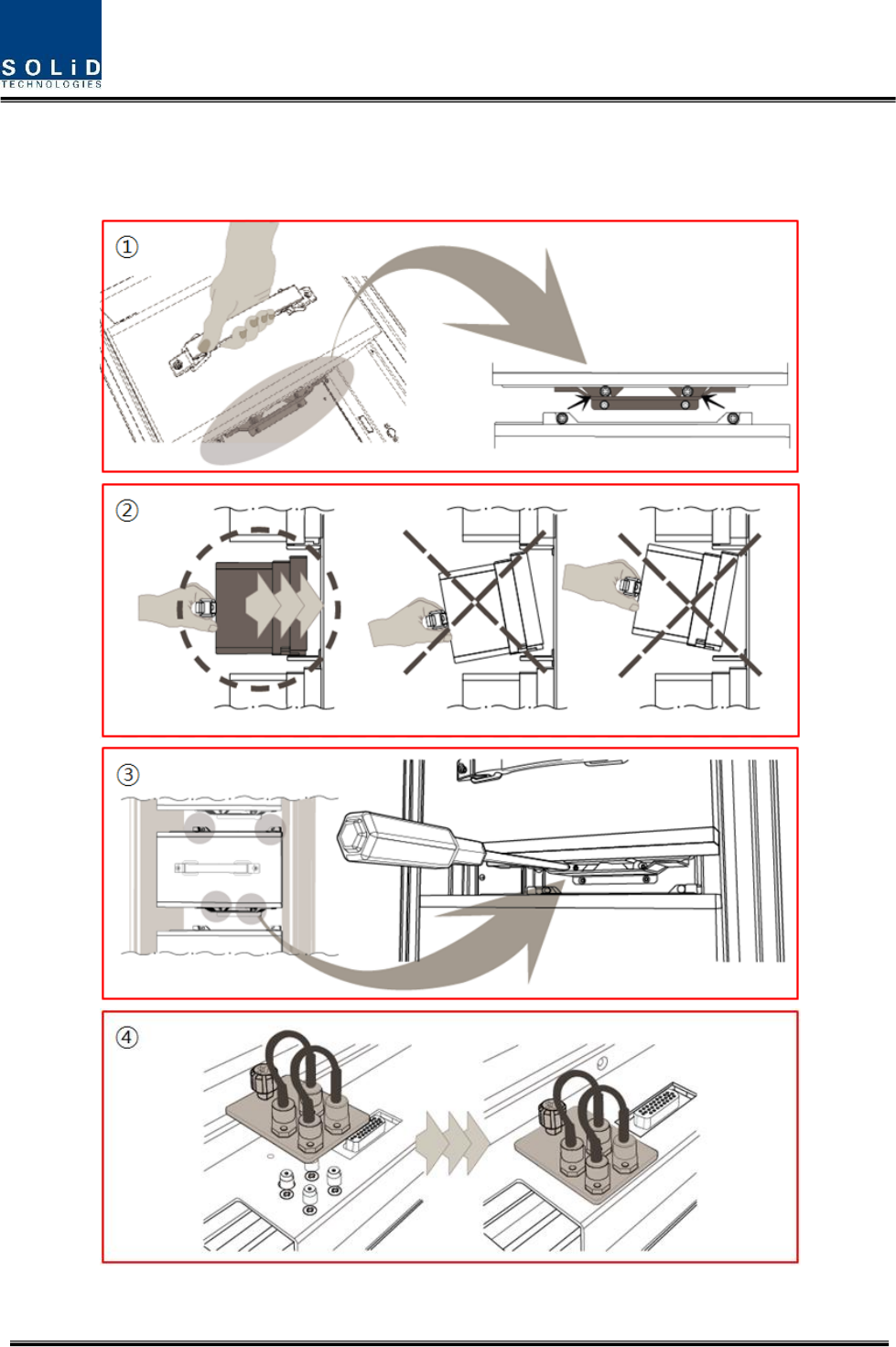
The Remote Unit holds a maximum of 6 MRDUs. Guide brackets on the bottom of each MRDU slot
simplify installation as described below. MRDU installation requires a +No.1 tip size screwdriver.
Figure 4.13 – How to mount MRDU
Confidential & Proprietary 32/39
The procedures are
1. Lift the MRDU onto the guide bracket and ensure the MRDU is level left to right
2. Push the MRDU into the corresponding slot in the direction of the heat sink while levelling the
MRDU to guide bracket
3. Make sure the MRDU is firmly inserted into the corresponding slot. Tighten the 4 corner
screws to secure the unit
4. Install MRDU blank cards in all unused slots in the remote. First insert the blank card into the
corresponding slot, then tighten the captive screw to secure it
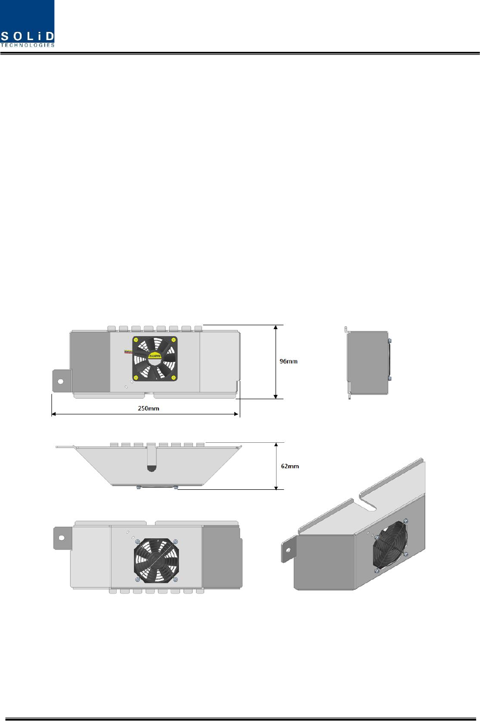
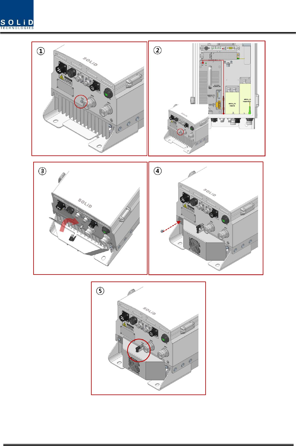
4.1.7 How to mount FAN Unit
FAN unit is required to be installed on the bottom of the 5W remote as shown in the below figure.
In the case that MROU temperature on GUI exceeds 70℃ (1580F), the fan unit is required to be
installed on the bottom of the remote unit.
Figure 4.14 – How to mount FAN Unit
Confidential & Proprietary 33/39
Figure 4.15 – How to mount FAN Unit

Confidential & Proprietary 34/39
The procedures are
1. Remove dummy bolt attached at FAN Port
2. Connect internal FAN cable to the FAN Port, and connect with the connector located on the
top of PSU.
3. Install fan unit to the bottom of 5W remote with aligning heatsink pin to the guided groove.
4. Secure the fan unit by tightening M6 screw located on the left corner.
5. After securing the FAN Unit, connect the cable from FAN unit to FAN port.

Confidential & Proprietary 36/39
5.1 Physical Specifications
Parameter
ROU
Nominal Impedance(input and output)
50 ohm
RF Connectors
DIN Female (7/16)
Mounting Type
Wall Mounting
Serial Interface connector
(1) RS-232 9-pin
D-sub, male
Fiber connector
(1) SC/APC for ODU
LED Alarm and Status Indicator
Power LED
TX LED
RX LED
LD LED
PD LED
ALARM LED
RESET Button
AC Power
108~132V AC, 50/60Hz
DC Power
-40.8 ~ -57.6V DC
Environmental Condition & IP Rating
IP66
Maximum Power Consumption
510W at full load
at full load
at full load
Enclosure Dimensions (mm)
320 x 1165 x 260mm
Weight (Full Load)
62kg
Optical Data
Wavelength TX/RX
1310/1550nm
Maximum Optical Loss
10dBo
Fiber Optic Connector
SC/APC
Confidential & Proprietary 37/39
5.2 RF performance
MRDU Specifications Per band
Downlink
Unit naming
Description
Gain(dB)
Bandwidth(MHz)
output power(dBm)
Frequency range
MRDU 850C
Single,
49
25
+39
869 - 894MHz
MRDU 850IC
Dual,
49
49
7
25
+39
+39
862 - 869MHz
869 - 894MHz
MRDU 1900P
Single,
53
65
+39
1930 - 1995MHz
MRDU 700LTE
Single,
49
28
+39
728 - 756MHz
MRDU AWS-1
Single,
53
45
+39
2110 - 2155MHz
MRDU 700LTE_MIMO
Single,
53
28
+39
728 - 756MHz
MRDU AWS-1_MIMO
Single,
53
45
+39
2110 - 2155MHz
MRDU 900I
Single,
49
12
+39
929 - 941MHz
MRDU 700P+800
Dual,
49
49
17
10
+39
+39
758 - 775MHz
851 - 861MHz
Uplink
Unit naming
Description
Gain(dB)
Bandwidth(MHz)
output power(dBm)
Frequency range
MRDU 850C
Single,
47
25
-5
824 - 849MHz
MRDU 850IC
Dual,
47
47
7
25
-5
-5
817 - 824MHz
824 - 849MHz
MRDU 1900P
Single,
47
65
-5
1850 - 1915MHz
MRDU 700LTE
Single,
47
47
17
10
-5
-5
699 - 716MHz
777 – 787MHz
MRDU AWS-1
Single,
47
45
-5
1710 – 1755MHz
MRDU 700LTE_MIMO
Single,
47
47
17
10
-5
-5
699 - 716MHz
777 – 787MHz
MRDU AWS-1_MIMO
Single,
47
45
-5
1710 – 1755MHz
MRDU 900I
Single,
47
6
-5
896 - 902MHz
MRDU 700P+800
Dual,
47
47
17
10
-5
-5
788 - 805MHz
806 - 816MHz

Confidential & Proprietary 38/39
5.3 Certification
Title
Standards
Remarks
Environmental
Temperature range
-25°C to +55°C/ -13 to 131°F
Ambient Temperature
Humidity Range
0% ~ 90%
Non-condensing
Sealing (Remote
Unit)
IEC 60 529 EN 60 529
IP66 Complaint
RSS-GEN, Sec. 7.1.2 – (transmitters)
Under Industry Canada regulations, this radio transmitter may only operate using an antenna of a type
and maximum (or lesser) gain approved for the transmitter by Industry Canada. To reduce potential
radio interference to other users, the antenna type and its gain should be so chosen that the equivalent
isotropically radiated power (e.i.r.p.) is not more than that necessary for successful communication.
Conformément à la réglementation d’Industrie Canada, le présent émetteur radio peut fonctionneravec
une antenne d’un type et d’un gain maximal (ou inférieur) approuvé pour l’émetteur par Industrie
Canada. Dans le but de réduire les risques de brouillage radioélectrique à l’intention desautres
utilisateurs, il faut choisir le type d’antenne et son gain de sorte que la puissance isotroperayonnée
quivalente (p.i.r.e.) ne dépassepas l’intensité nécessaire à l’établissement d’une communication
satisfaisante.
RSS-GEN, Sec. 7.1.2 – (detachable antennas)
This radio transmitter (identify the device by certification number, or model number if Category II)has
been approved by Industry Canada to operate with the antenna types listed below with the maximum
permissible gain and required antenna impedance for each antenna type indicated. Antenna types not
included in this list, having a gain greater than the maximum gain indicated for that type, are strictly
prohibited for use with this device.
Le présent émetteur radio (identifier le dispositif par son numéro de certification ou son numéro de
modèle s’il fait partie du matériel de catégorie I) a été approuvé par Industrie Canada pour fonctionner
avec les types d’antenne énumérés ci-dessous et ayant un gain admissible maximal et l’impédance
requise pour chaque type d’antenne. Les types d’antenne non inclus dans cette liste,ou dont le gain est
supérieur au gain maximal indiqué, sont strictement interdits pour l’exploitation de l’émetteur.

Confidential & Proprietary 39/39
RF Radiation Exposure
This equipment complies with RF radiation exposure limits set forth for an uncontrolled environment.
This equipment should be installed and operated with a minimum distance of 300 cm between the
radiator and your body. This transmitter must not be co-located or operating in conjunction with any
other antenna or transmitter. RF exposure will be addressed at time of installation and the use of higher
gain antennas may require larger separation distances.
RSS-102 RF Exposure
L’antenne (ou les antennes) doit être installée de façon à maintenir à tout instant une distance
minimum de au moins 300 cm entre la source de radiation (l’antenne) et toute personne physique. Cet
appareil ne doit pas être installé ou utilisé en conjonction avec une autre antenne ou émetteur.