SOLiD HMR25TDD Alliance 5W User Manual MB DAS
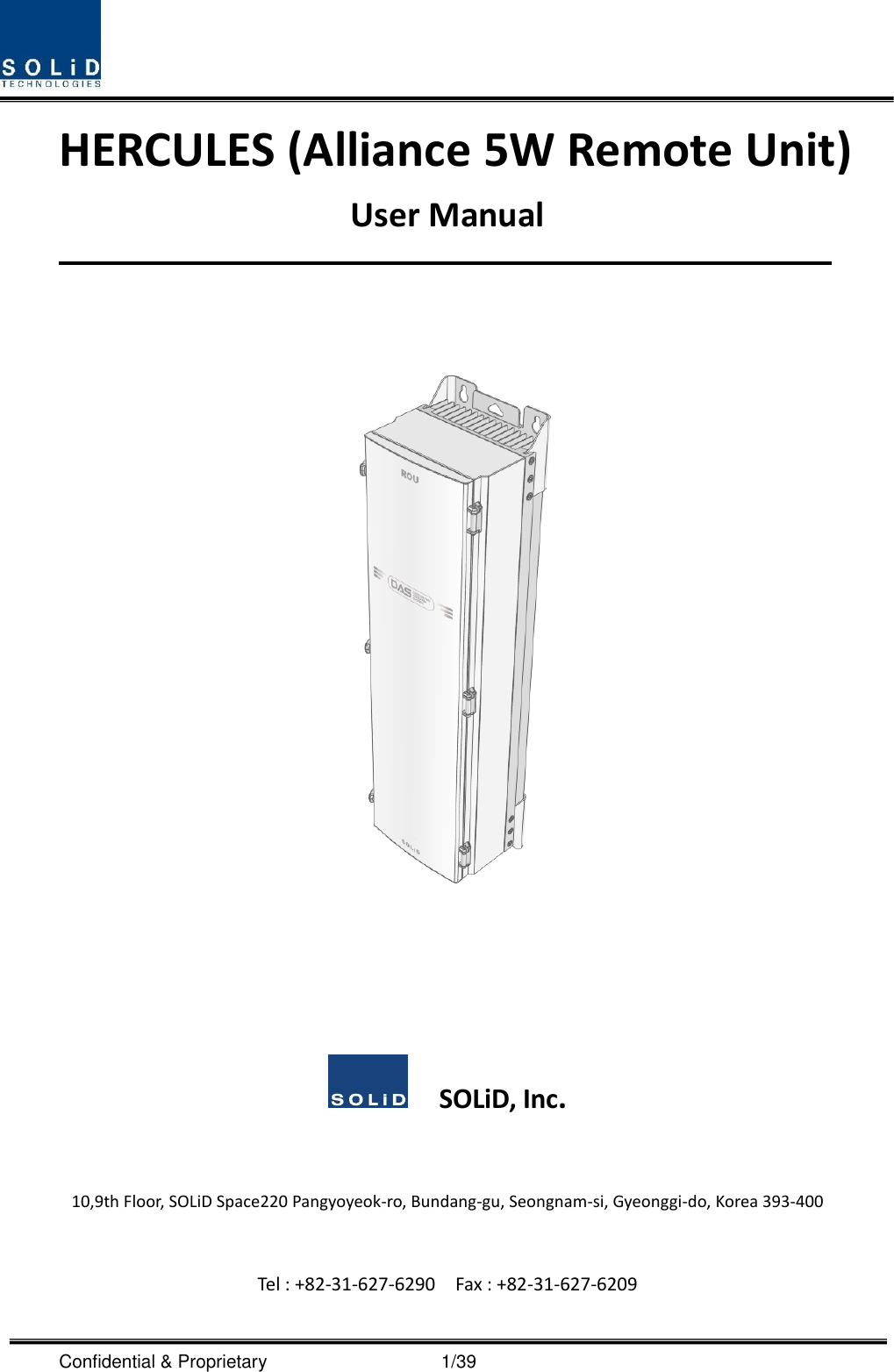
SOLiD, Inc. Alliance 5W MB DAS
UserManual.wiki
>
SOLiD
>
HMR25TDD User Manual
MRDU_2500_60TDD Users manual
Navigation menu
Upload a User Manual
Namespaces
Wiki Guide
HTML
PDF
Info
Views
User Manual
Discussion / Help
Navigation
![Confidential & Proprietary 2/39 REVISION HISTORY Version Issue Date No. of Pages Initials Details of Revision Changes V 1.0 September. 07, 2014 Original V1.1 June 29, 2017 all Update Change the model name from AWS-1_M to AWS13_M (Updated RDU CPU Firmware) V1.2 Sep 9, 2017 37,38 Update Change name of Gain item Gain[dB] to Gain[dB] (Only RU) Technical Support SOLiD serial numbers must be available to authorize technical support and/or to establish a return authorization for defective units. The serial numbers are located on the back of the unit, as well as on the box in which they were delivered. Additional support information may be obtained by accessing the SOLiD Tehcnology, Inc. website at www.solid.co.kr or send email at kehan@solid.co.kr This manual is produced by Global Business Division Business Team 1. Printed in Korea.](https://usermanual.wiki/SOLiD/HMR25TDD/User-Guide-3776851-Page-2.png)
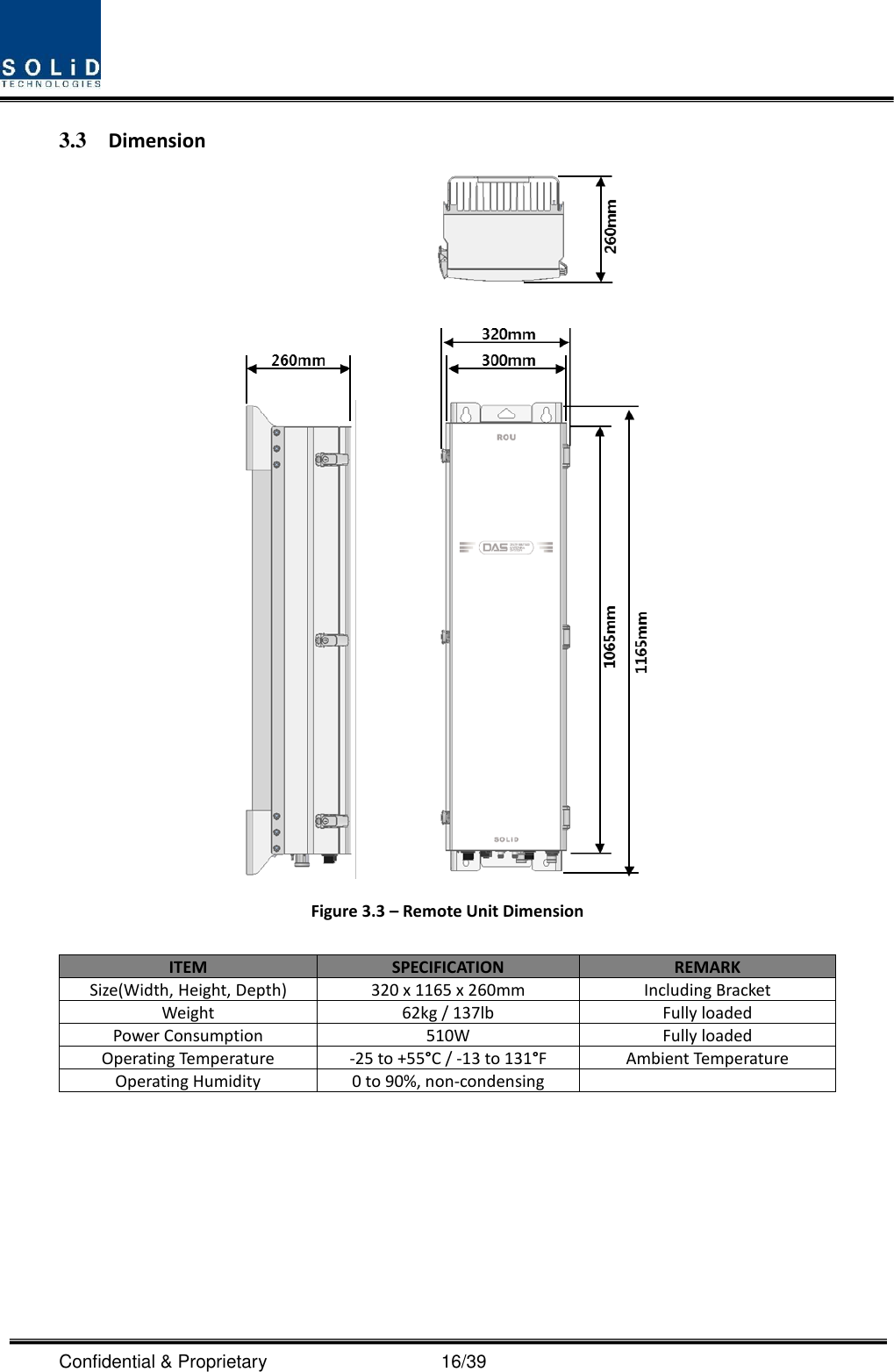
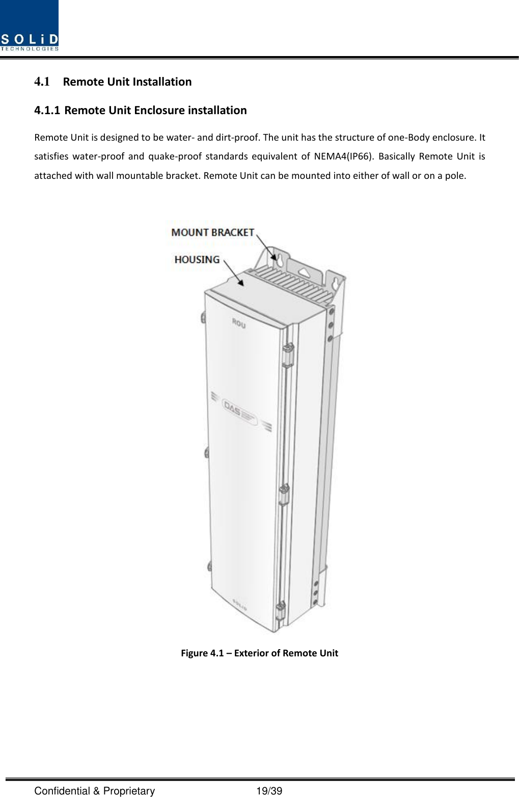
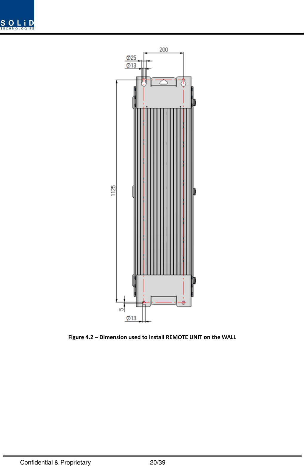
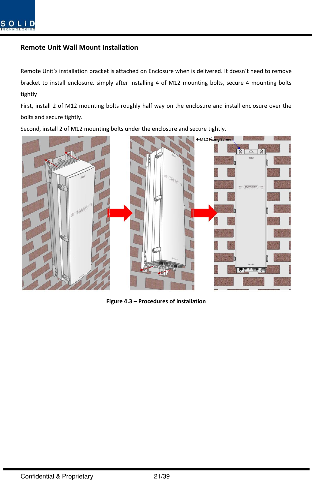
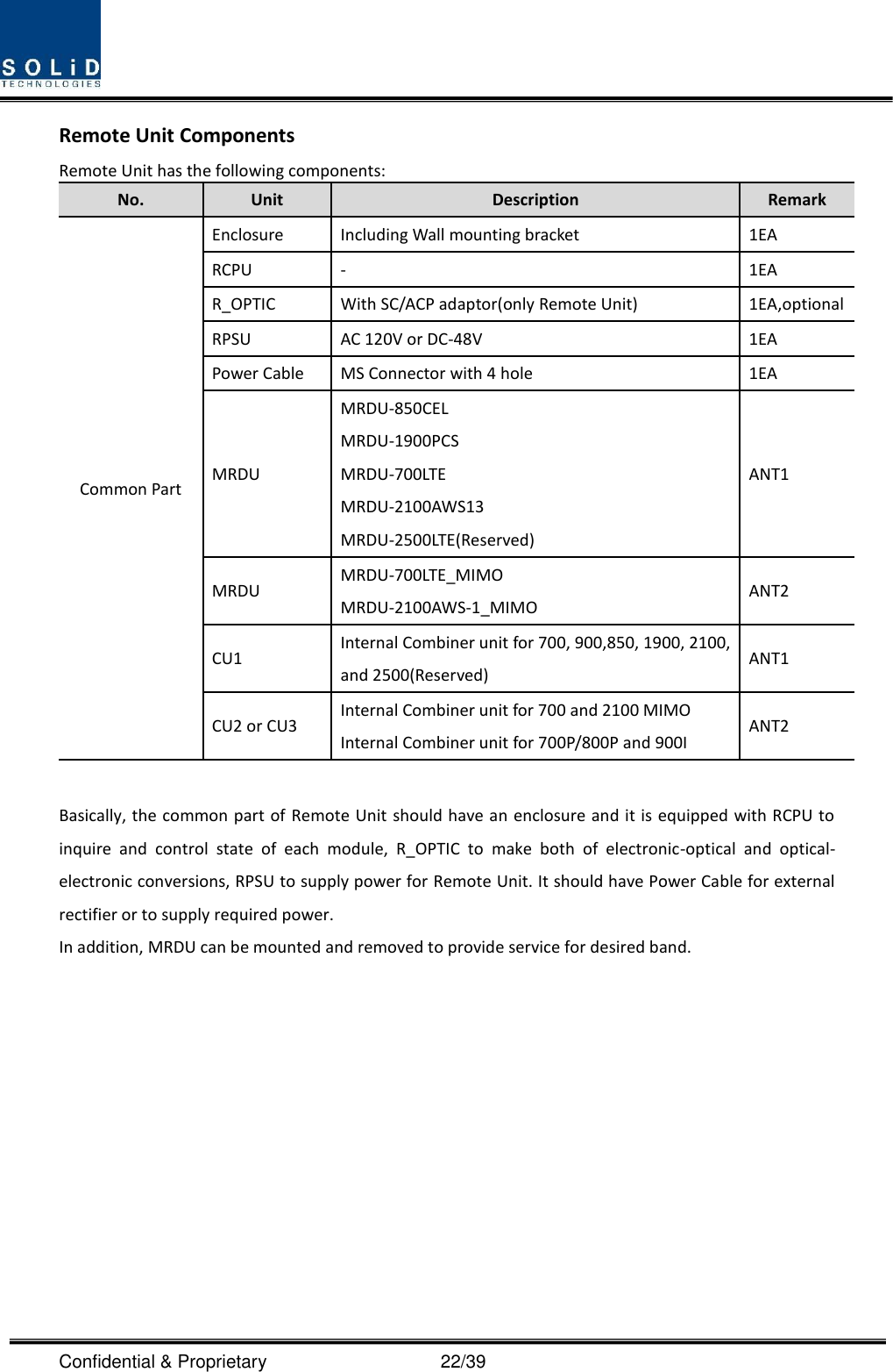
![Confidential & Proprietary 17/39 Section4 System Installation 5.1 Remote Unit Installation This chapter describes how to install each unit and optical cables, along with power cabling method. In detail, the chapter describes how to install shelves or enclosures of each unit, Power Cabling method and Optic Cabling and RF Interface. The needed accessories and tools are list up in the below table. Steps for installation Accessories Included Tool Remark Remote Enclosure Installation M12 Bolt (4EA) X Spanner(19mm) - Power Connection_AC AC 120V power cable (1EA) [2 meter, with MIL-5015 type Connector (MS-3106A- 18-10S) at one end, AC Plug at another end] ○ - - Power Connection_DC DC -48V power cable (1EA) [2 meter, with MIL-5015 type Connector (MS-3106A- 18-10S) at one end, 4.5 ø square lugs at another end] ○ - - Optical Connection Optical Cable Assembly Connector (1EA) [SOLI-FIBER-ASS’Y, by LTW] ○ - For more details,](https://usermanual.wiki/SOLiD/HMR25TDD/User-Guide-3776851-Page-17.png)
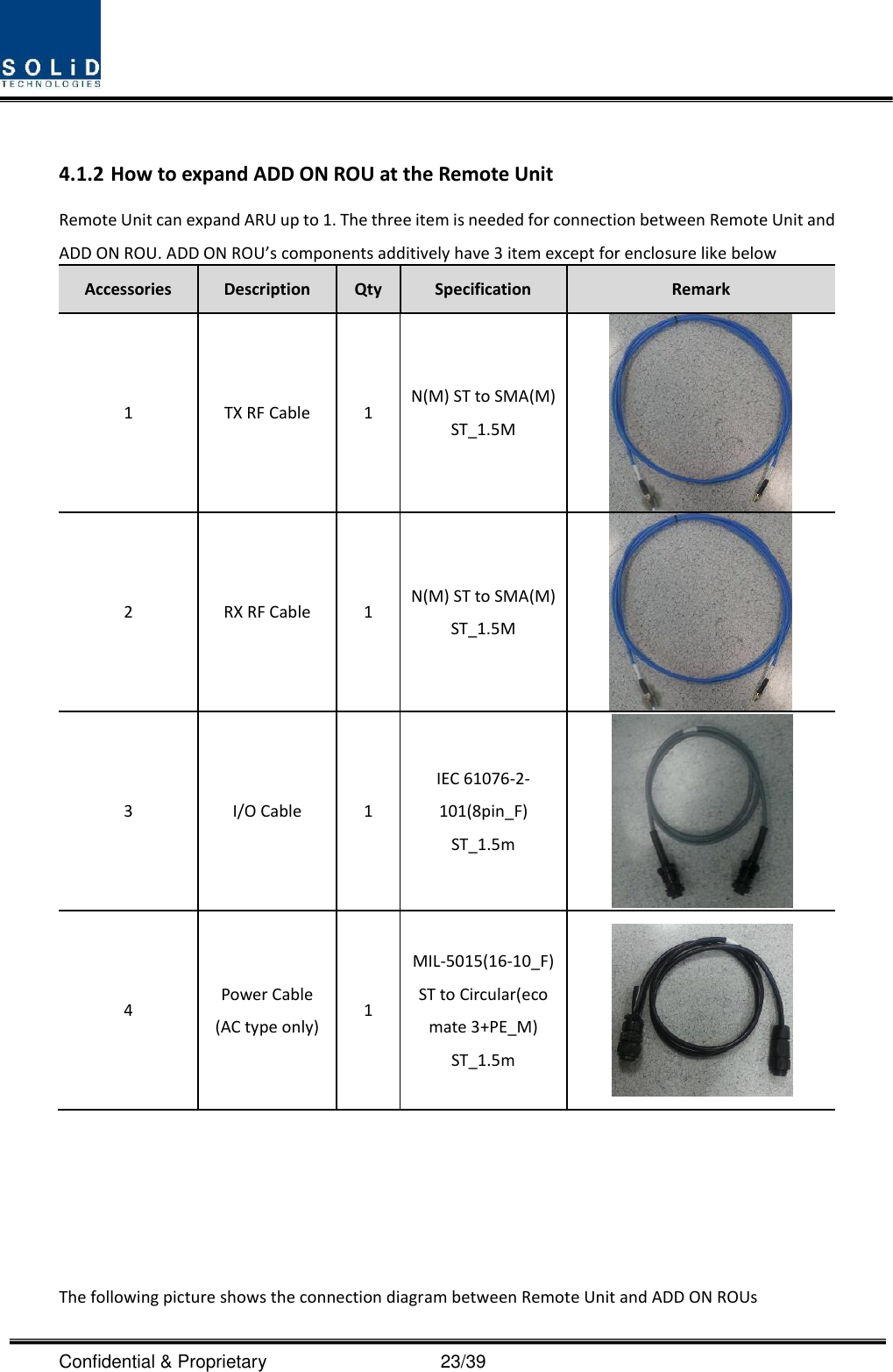
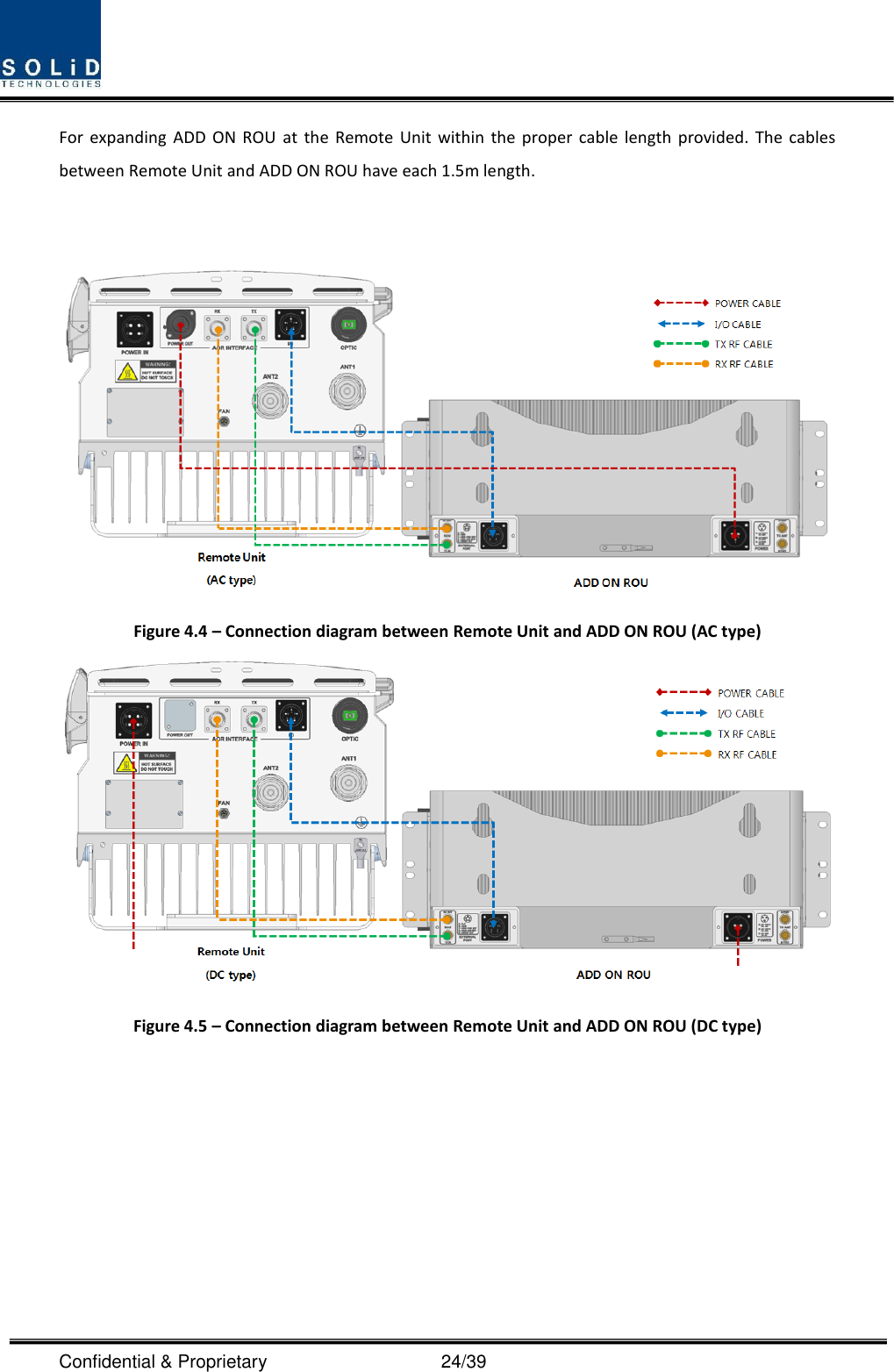
![Confidential & Proprietary 18/39 OPTIC SC/APC Cable (1EA) X - refer to 4.1.5 Ground Connection M6 Screw (1EA) ○ No.2 Screw driver (+) For more details, refer to 4.1.4 Lug (1EA) ○ Crimping Tool Max. AWG #6 Cable X Antennal Connection RF Cable (1 or 2EA) X Spanner (33mm) 2 EA is required in case of MIMO. MRDU Installation - - No.1 Screw driver (+) For more details, refer to 4.1.6 Connection with ADD ON ROU AC power cable (1 EA) [1.5 meter, with MIL-5015 type Connector (MS-3106A-16-10S) and Circular Connector (C016_20H003_100_12, by LTW)] ○ - - Data Interface cable (1 EA) [1.5 meter, with MIL-5015 type Connector (MS-3106A-14S-5S) at both ends] ○ - - RF interface cable (2EA) [1.5 meter, with N male connector at both ends] ○ - - FAN Unit (Option) Inner Fan Cable ○ Spanner (10mm)- For more details, refer to 4.1.7 Fan Unit ○ - M6 Screw (1EA) X No.2 Screw driver (+)](https://usermanual.wiki/SOLiD/HMR25TDD/User-Guide-3776851-Page-18.png)
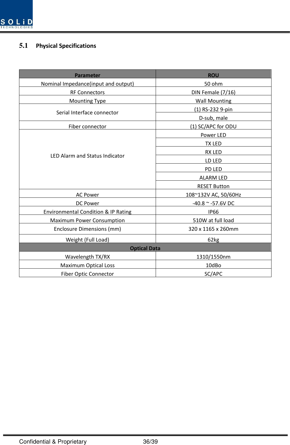
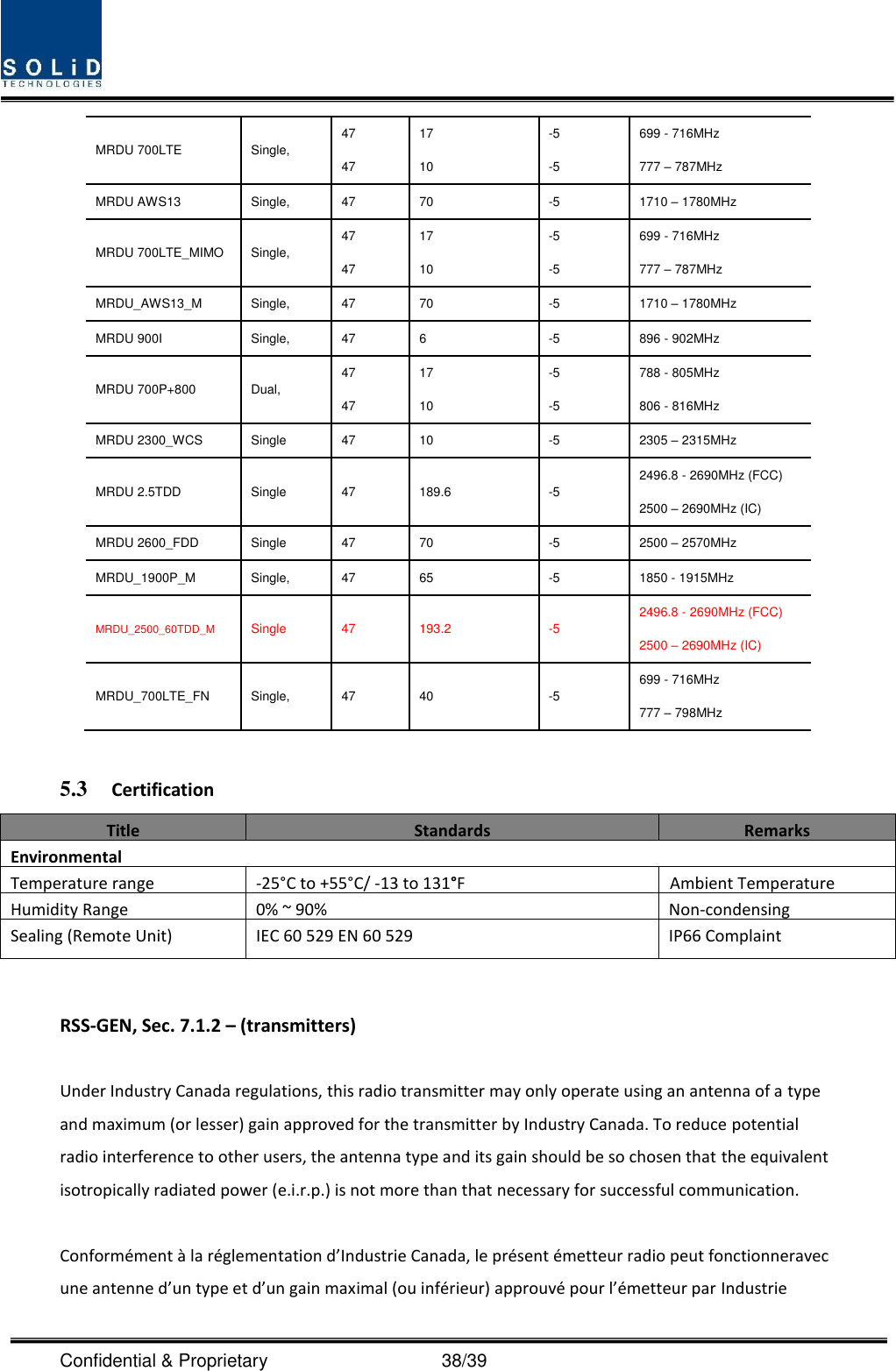
![Confidential & Proprietary 37/39 5.2 RF performance MRDU Specifications Per band Downlink Unit naming Description Gain(dB) [Only RU] Bandwidth(MHz) output power(dBm) Frequency range MRDU 850C Single, 49 25 +39 869 - 894MHz MRDU 850IC Dual, 49 49 7 25 +37 +37 862 - 869MHz 869 - 894MHz MRDU 1900P Single, 53 65 +37 1930 - 1995MHz MRDU 700LTE Single, 49 28 +37 728 - 756MHz MRDU AWS13 Single, 54.2 70 +38.2 2110 - 2180MHz MRDU 700LTE_MIMO Single, 53 28 +37 728 - 756MHz MRDU_AWS13_M Single, 53 70 +37 2110 - 2180MHz MRDU 900I Single, 49 12 +37 929 - 941MHz MRDU 700P+800 Dual, 49 49 17 10 +37 +37 758 - 775MHz 851 - 861MHz MRDU 2300_WCS Single 53 10 +37 2350 – 2360MHz MRDU 2.5TDD Single 53 193.2 +37 2496.8 - 2690MHz (FCC) 2500 – 2690MHz (IC) MRDU 2600_FDD Single 53 70 +37 2620 – 2690MHz MRDU_1900P_M Single, 53 65 +37 1930 - 1995MHz MRDU_2500_60TDD_M Single 53 193.2 +37 2496.8 - 2690MHz (FCC) 2500 – 2690MHz (IC) MRDU_700LTE_FN Single, 49 40 +37 728 - 768MHz Uplink Unit naming Description Gain(dB) [Only RU] Bandwidth(MHz) output power(dBm) Frequency range MRDU 850C Single, 47 25 -5 824 - 849MHz MRDU 850IC Dual, 47 47 7 25 -5 -5 817 - 824MHz 824 - 849MHz MRDU 1900P Single, 47 65 -5 1850 - 1915MHz](https://usermanual.wiki/SOLiD/HMR25TDD/User-Guide-3776851-Page-37.png)