SOLiD NH700L HPRD (High Power Remote Drive Unit) User Manual MB DAS
SOLiD, Inc. HPRD (High Power Remote Drive Unit) MB DAS
UserManual.wiki
>
SOLiD
>
NH700L User Manual
installation Manual
Navigation menu
Upload a User Manual
Namespaces
Wiki Guide
HTML
PDF
Info
Views
User Manual
Discussion / Help
Navigation
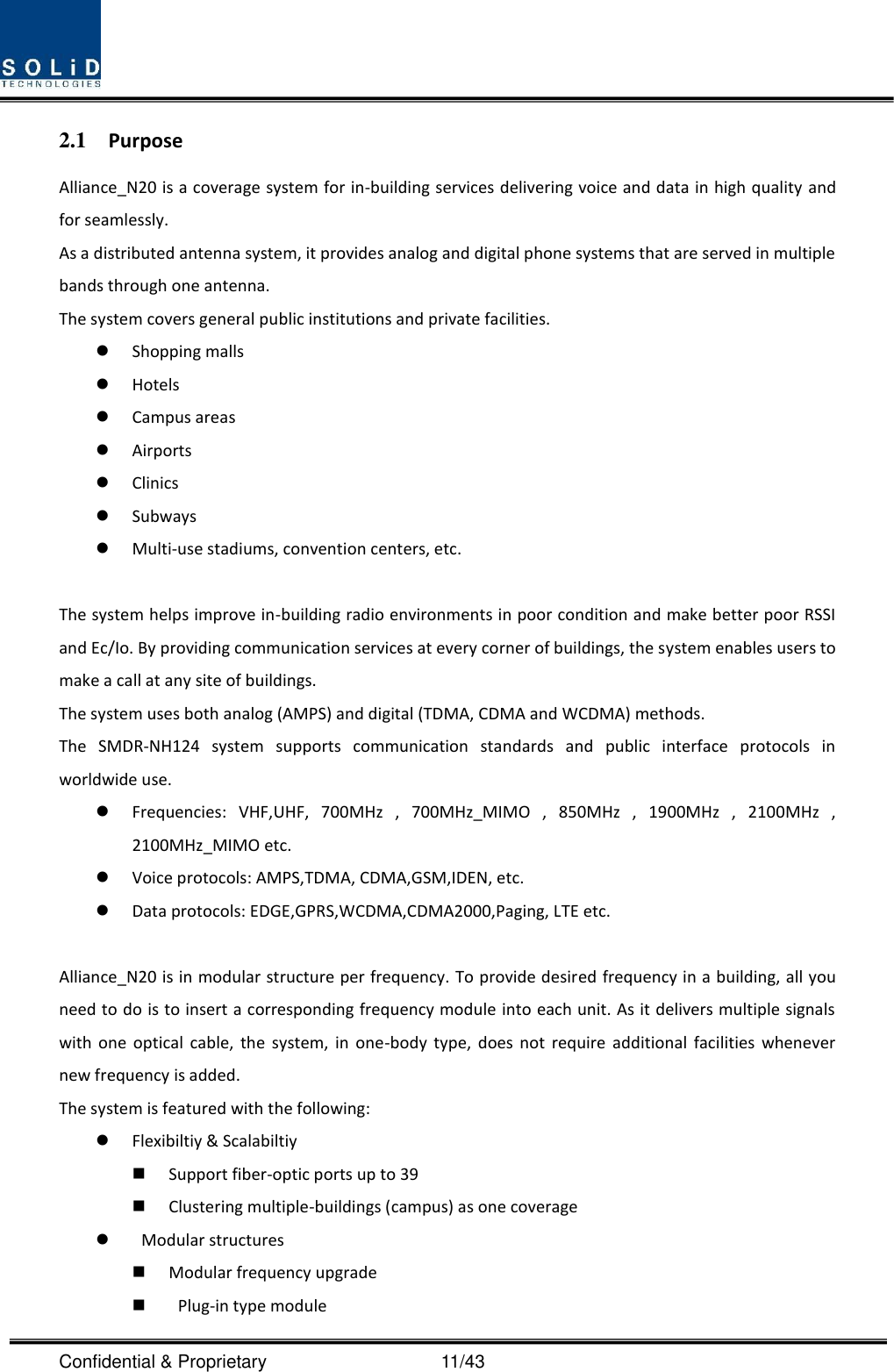
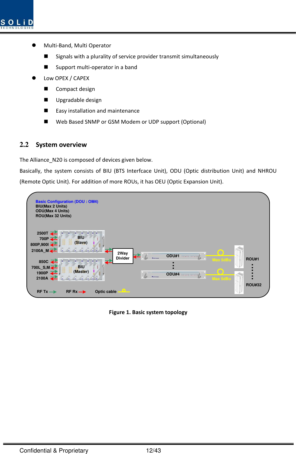
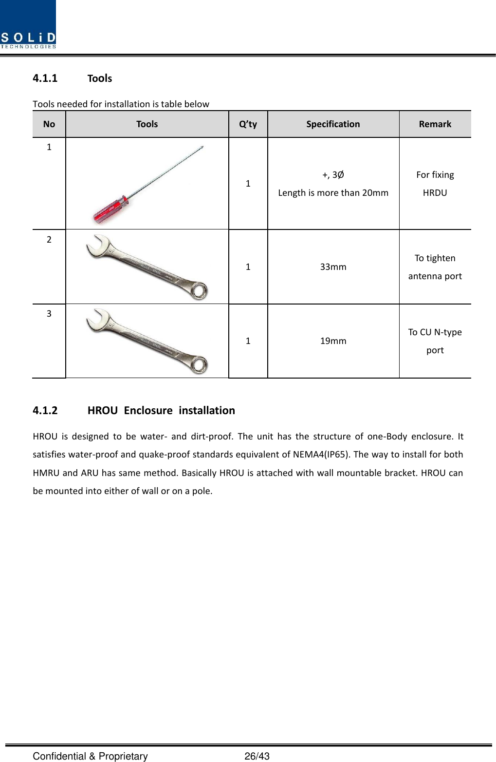
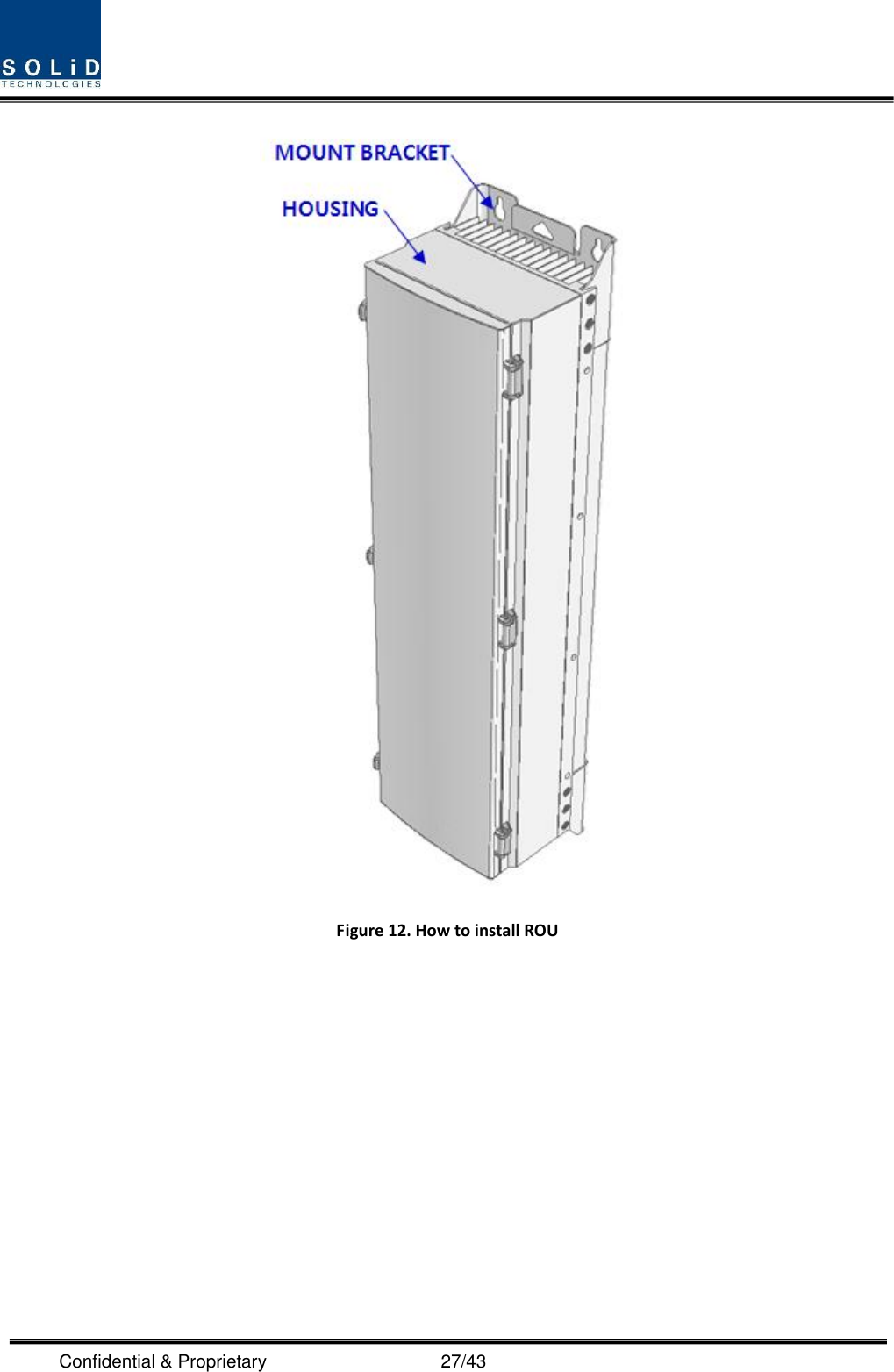
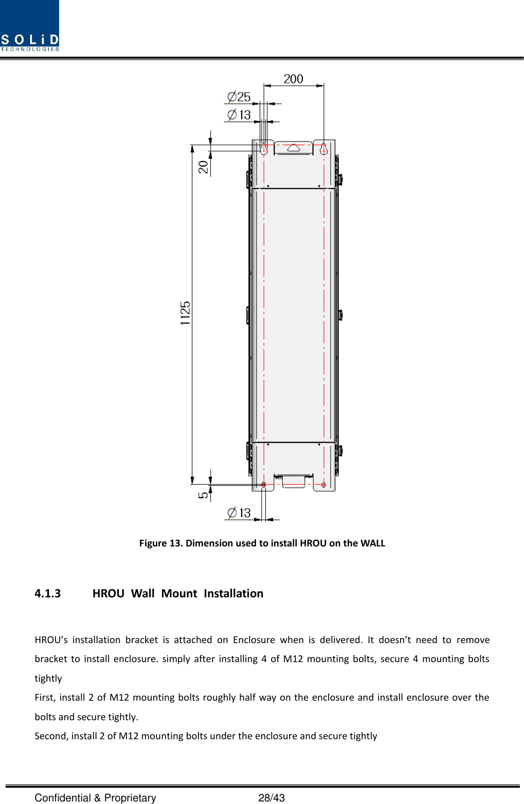
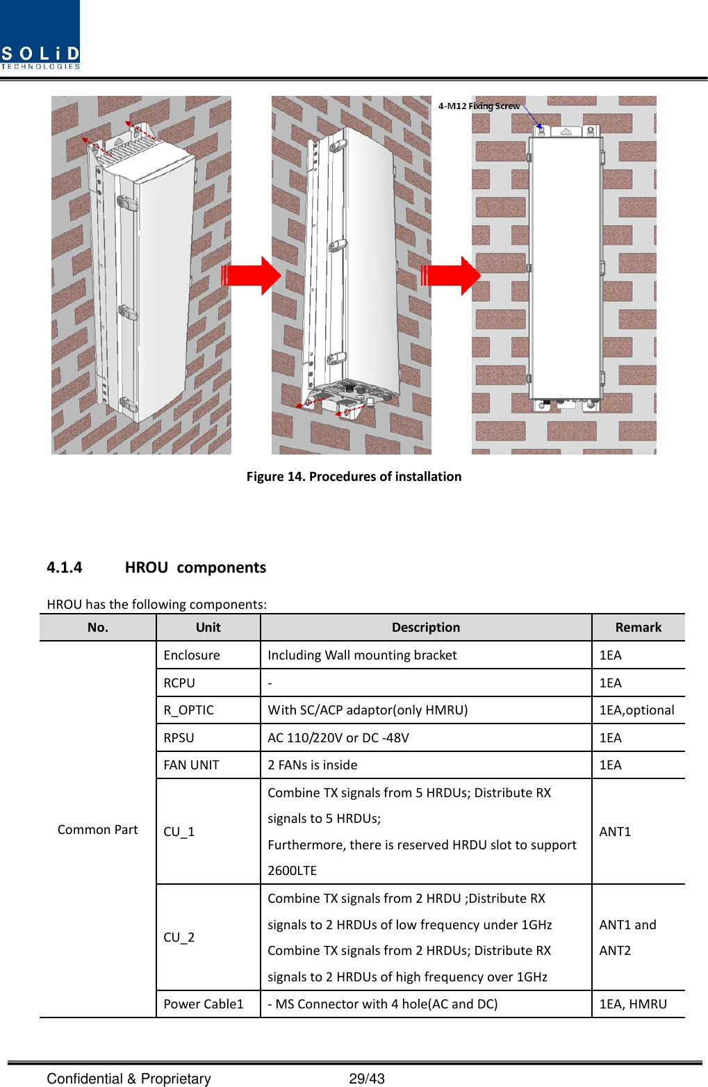
![Confidential & Proprietary 13/43 BIU(Master)BIU(Slave)2WayDivider850C700L_S,M1900P2100AMax 5dBoMax 5dBo......ROU#1ROU#32......ROU#1ROU#28......ODU#1ODU#4OEU#4OEU#1RF Tx RF RxMax 5dBoMax 5dBoMax 5dBoOptic cableExpansion Configuration (DOU : OM4)BIU(Max 2 Units)ODU(Max 4 Units)ROU(Max 60 Units)2100A_M800P,900I700P2500T Figure 2. Expansion system topology System topology Charts (OM4; 4Optical port) System elements Optical Loss [dBo] Max. RUs BIU – ODU(DOUx1) – ROU 1~5dBo 4 BIU – ODU(DOUx2) – ROU 1~5dBo 8 BIU – 4ODU(DOUx2) – ROU 1~5dBo 32 BIU – 4ODU(DOUx2)-4OEU(DOUx2) – ROU 1~5dBo 60 System topology Charts (OM1; 1Optical port) System elements Optical Loss [dBo] Max. RUs BIU – ODU(DOUx1) – ROU 1~10dBo 1 BIU – ODU(DOUx2) – ROU 1~10dBo 2 BIU – 4ODU(DOUx2) – ROU 1~10dBo 8 BIU – 4ODU(DOUx2)-4OEU(DOUx2) – ROU 1~10dBo 12](https://usermanual.wiki/SOLiD/NH700L/User-Guide-2406224-Page-13.png)