SOLiD NH850IC HPRD (High Power Remote Drive Unit) User Manual
SOLiD, Inc. HPRD (High Power Remote Drive Unit)
SOLiD >
User Manual
Confidential & Proprietary 1/44
ALLIANCE_N20(RemoteUnit)
UserManual
DocumentReference:
Version:V1.0
DocumentStatus:Release1
IssueDate:July.16,2014
Author:HwansunLee
Department:R&DDivisionTeam3
AuthorizingManager: YoungshinYeo

Confidential & Proprietary 2/44
REVISIONHISTORY
VersionIssueDateNo.of
PagesInitialsDetailsofRevisionChanges
V1.0Aug.20,2014 Original
TechnicalSupport
SOLiDserialnumbersmustbeavailabletoauthorizetechnicalsupportand/ortoestablishareturn
authorizationfordefectiveunits.Theserialnumbersarelocatedonthebackoftheunit,aswellason
theboxinwhichtheyweredelivered.Additionalsupportinformationmaybeobtainedbyaccessingthe
SOLiDTehcnology,Inc.websiteatwww.solid.co.krorsendemailatsjkim@st.co.kr
ThismanualisproducedbyGlobalBusinessDivisionBusinessTeam1.PrintedinKorea.

Confidential & Proprietary 3/44
Contents
Section1 Safety&CertificationNotice ......................................................................... 6
Section2 SystemOverview ....................................................................................... 10
2.1 Purpose ........................................................................................................... 11
2.2 Systemoverview .............................................................................................. 12
Section3 SystemconfigurationandFunctions ............................................................ 14
3.1 HROU(HighpowerRemoteOpticUnit) ............................................................. 14
3.1.1 SpecificationsofHROU ............................................................................... 15
3.1.2 BlockDiagramofHROU .............................................................................. 16
3.1.2.1 HMRUblockdiagram ................................................................................. 16
3.1.2.2 HROUinnerlook ........................................................................................ 17
3.1.2.3 HROUpartlist ............................................................................................ 18
3.1.3 Functionbyunit ......................................................................................... 19
3.1.3.1 HighRemoteDriveUnit(HRDU) .................................................................. 19
3.1.3.2 RemotePowerSupplyUnit(RPSU) ............................................................. 21
3.1.3.3 RemoteOptic(ROPTIC) .............................................................................. 22
3.1.3.4 RemoteCentralProcessorUnit(RCPU) ........................................................ 23
3.1.4 BottomofHROU ........................................................................................ 24
3.1.4.1 Functions .................................................................................................. 24
Section4 SystemInstallation ..................................................................................... 26
4.1 HROUInstallation ............................................................................................ 26
4.1.1 Tools ............................................................................................................... 27
4.1.2 HROUEnclosureinstallation ............................................................................. 27
4.1.3 HROUWallMountInstallation .......................................................................... 29
4.1.4 HROUcomponents ........................................................................................... 30
4.1.5 HROUPowerCabling ........................................................................................ 32
4.1.6 HROUGroundcabling....................................................................................... 34
4.1.9 MountingofHRDU ........................................................................................... 41

Confidential & Proprietary 4/44
ContentsofFigure
Figure1.Basicsystemtopology .......................................................................... 12
Figure2.Expansionsystemtopology .................................................................. 13
Figure3.HROUouterLook ................................................................................ 15
Figure4.HMRUBlockdiagram ........................................................................... 16
Figure5.InsideofRemoteUnit ....................................................................... 17
Figure6.HRDUOuterLook ................................................................................ 19
Figure7.AC‐DCRPSUOuterLook ....................................................................... 21
Figure8.DC‐DCRPSUOuterLook ....................................................................... 22
Figure9.ROPTICOuterLook ............................................................................. 23
Figure10.RCPUOuterLook ............................................................................... 23
Figure11.TheBottomLookofHROU .................................................................. 24
Figure12.HowtoinstallROU ............................................................................. 28
Figure13.DimensionusedtoinstallHROUontheWALL ...................................... 29
Figure14.Proceduresofinstallation ................................................................... 30
Figure15.LocationofGroundTerminal ............................................................... 34
Figure16.InformationofTerminal ..................................................................... 35
Figure17.HowtoinstallGroundTerminal ........................................................... 36
Figure18.LocationofOpticalConnector ............................................................. 37
Figure19.InformationofOpticalConnector ........................................................ 37
Figure20.HowtoinstallOpticalCabling ............................................................. 38
Figure21.LocationofALMIN/OUTConnector .................................................... 39
Figure22.InformationofALMIN/OUTConnector ............................................... 39
Figure23.HowtoinstallALMIN/OUTCabling ..................................................... 40

Confidential & Proprietary 5/44
Figure24.HowtomountHRDU ......................................................................... 41
Figure25.HowtomountHRDU ......................................................................... 42

Confidential & Proprietary 6/44
Section1
Safety&CertificationNotice

Confidential & Proprietary 7/44
“OnlyqualifiedpersonnelshouldhandletheDASequipment.Anypersoninvolvedin
installationorserviceoftheDASshouldunderstandandfollowthesesafetyguidelines.”
‐ Obeyallgeneralandregionalinstallationandsafetyregulationsrelatingtoworkonhighvoltage
installations,aswellasregulationscoveringcorrectuseoftoolsandpersonalprotectiveequipment.
‐Thepowersupplyunitinrepeaterscontainsdangerousvoltagelevel,whichcancauseelectricshock.
Switchthemainsoffpriortoanyworkinsucharepeater.Anylocalregulationsaretobefollowed
whenservicingrepeaters.
‐Whenworkingwithunitsoutdoors,makesuretosecurelyfastenthedoororcoverinanopenposition
topreventthedoorfromslammingshutinwindyconditions..
‐Usethisunitonlyforthepurposespecifiedbythemanufacturer.Donotcarryoutanymodificationsor
fitanysparepartswhicharenotsoldorrecommendedbythemanufacturer.Thiscouldcausefires,
electricshockorotherinjuries.
‐AnyDASsystemorFiberBDAwillgenerateradio(RF)signalsandcontinuouslyemitRFenergy.Avoid
prolongedexposuretotheantennas.SOLiDrecommendsmaintaininga500cmminimumclearance
fromtheantennawhilethesystemisoperating.
‐AntennasmustbeinstalledinaccordancewithFCC90.635.With14.8dBigainantennastheheightof
theantennaaboveaverageterrain(HAAT)mustnotexceed439m.Fordifferentgainantennasrefer
totherelevantrules
‐Donotoperatethisunitonorclosetoflammablematerials,astheunitmayreachhightemperatures
duetopowerdissipation.
‐Donotuseanysolvents,chemicals,orcleaningsolutionscontainingalcohol,ammonia,orabrasiveson
theDASequipment.Alcoholmaybeusedtocleanfiberopticcablingendsandconnectors.
‐Topreventelectricalshock,switchthemainpowersupplyoffpriortoworkingwiththeDASSystemor
FiberBDA.Neverinstalloruseelectricalequipmentinawetlocationorduringalightningstorm.
‐Donotlookintotheendsofanyopticalfiberordirectlyintotheopticaltransceiverofanydigitalunit.
Useanopticalspectrumanalyzertoverifyactivefibers.Placeaprotectivecapoveranyradiating
transceiveroropticalfiberconnectortoavoidthepotentialofradiationexposure.
‐Allowsufficientfiberlengthtopermitroutingwithoutseverebends.
‐Forpluggableequipment,makesuretoinstallthesocketoutletneartheequipmentsothatitiseasily
accessible.
‐Areadilyaccessibledisconnectdeviceshallbeincorporatedexternaltotheequipment.

Confidential & Proprietary 8/44
‐Thispowerofthissystemshallbesuppliedthroughwiringinstalledinanormalbuilding.
Ifpowereddirectlyfromthemainsdistributionsystem,itshallbeusedadditionalprotection,suchas
overvoltageprotectiondevice
‐Only50ohmratedantennas,cablesandpassiveequipmentshallbeusedwiththisremote.Any
equipmentattachedtothisdevicenotmeetingthisstandardmaycausedegradationandunwanted
signalsinthebi‐directionalsystem.Allcomponentsconnectedtothisdevicemustoperateinthe
frequencyrangeofthisdevice.
‐Only50ohmratedantennas,cablesandpassivecomponentsoperatingfrom150‐3GHzshallbeused
withthisdevice.
‐ TheheadendunitmustalwaysbeconnectedtotheBaseStationusingadirectcabledconnection.
Thissystemhasnotbeenapprovedforusewithawirelessconnectionviaserverantennatothebase
station.
‐AccesscanonlybegainedbySERVICEPERSONSorbyUSERSwhohavebeeninstructedaboutthe
reasonsfortherestrictionsappliedtothelocationandaboutanyprecautionsthatshallbetaken;and
‐AccessisthroughtheuseofaTOOLorlockandkey,orothermeansofsecurity,andisontrolledbythe
authorityresponsibleforthelocation.
‐Notice!BecarefulnottotouchtheHeat‐sinkpartduetohightemperature.
‐Signalboosterwarninglabelmessageshouldinclude

Confidential & Proprietary 9/44
‐Certification
FCC:ThisequipmentcomplieswiththeapplicablesectionsofTitle47CFRParts15,22,24,27and
90(ClassB)
UL/CUL:ThisequipmentcomplieswithULandCUL1950‐1Standardforsafetyforinformation
technologyequipment,includingelectricalbusinessequipment
FDA/CDRH:ThisequipmentusesaClass1LASERaccordingtoFDA/CDRHRules.Thisproduct
conformstoallapplicablestandardsof21CFRChapter1,SubchaperJ,Part1040

Confidential & Proprietary 10/44
Section2
SystemOverview
2.1Purpose
2.2Systemoverview

Confidential & Proprietary 11/44
2.1 Purpose
Alliance_N20isacoveragesystemforin‐buildingservicesdeliveringvoiceanddatainhighqualityand
forseamlessly.
Asadistributedantennasystem,itprovidesanaloganddigitalphonesystemsthatareservedinmultiple
bandsthroughoneantenna.
Thesystemcoversgeneralpublicinstitutionsandprivatefacilities.
Shoppingmalls
Hotels
Campusareas
Airports
Clinics
Subways
Multi‐usestadiums,conventioncenters,etc.
Thesystemhelpsimprovein‐buildingradioenvironmentsinpoorconditionandmakebetterpoorRSSI
andEc/Io.Byprovidingcommunicationservicesateverycornerofbuildings,thesystemenablesusersto
makeacallatanysiteofbuildings.
Thesystemusesbothanalog(AMPS)anddigital(TDMA,CDMAandWCDMA)methods.
TheSMDR‐NH124systemsupportscommunicationstandardsandpublicinterfaceprotocolsin
worldwideuse.
Frequencies:VHF,UHF,700MHz,700MHz_MIMO,850MHz,1900MHz,2100MHz,
2100MHz_MIMOetc.
Voiceprotocols:AMPS,TDMA,CDMA,GSM,IDEN,etc.
Dataprotocols:EDGE,GPRS,WCDMA,CDMA2000,Paging,LTEetc.
Alliance_N20isinmodularstructureperfrequency.Toprovidedesiredfrequencyinabuilding,allyou
needtodoistoinsertacorrespondingfrequencymoduleintoeachunit.Asitdeliversmultiplesignals
withoneopticalcable,thesystem,inone‐bodytype,doesnotrequireadditionalfacilitieswhenever
newfrequencyisadded.
Thesystemisfeaturedwiththefollowing:
Flexibiltiy&Scalabiltiy
Supportfiber‐opticportsupto39
Clusteringmultiple‐buildings(campus)asonecoverage
Modularstructures
Modularfrequencyupgrade
Plug‐intypemodule
Confidential & Proprietary 12/44
Multi‐Band,MultiOperator
Signalswithapluralityofserviceprovidertransmitsimultaneously
Supportmulti‐operatorinaband
LowOPEX/CAPEX
Compactdesign
Upgradabledesign
Easyinstallationandmaintenance
WebBasedSNMPorGSMModemorUDPsupport(Optional)
2.2 Systemoverview
TheAlliance_N20iscomposedofdevicesgivenbelow.
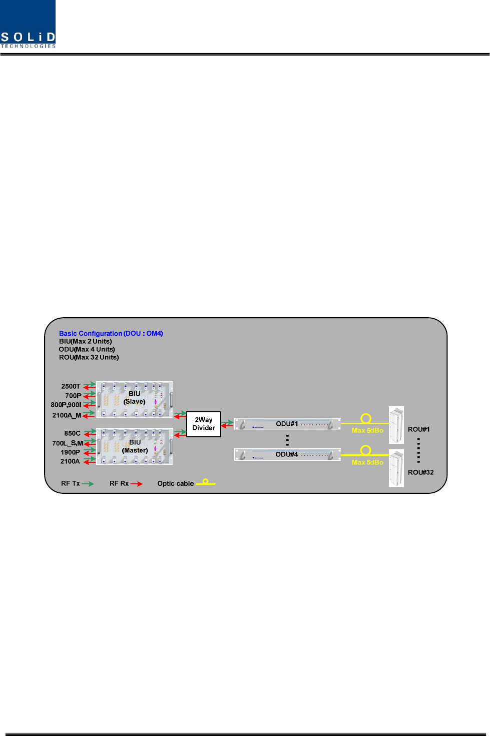
Basically,thesystemconsistsofBIU(BTSInterfcaceUnit),ODU(OpticdistributionUnit)andNHROU
(RemoteOpticUnit).ForadditionofmoreROUs,ithasOEU(OpticExpansionUnit).
Figure1.Basicsystemtopology
Confidential & Proprietary 13/44
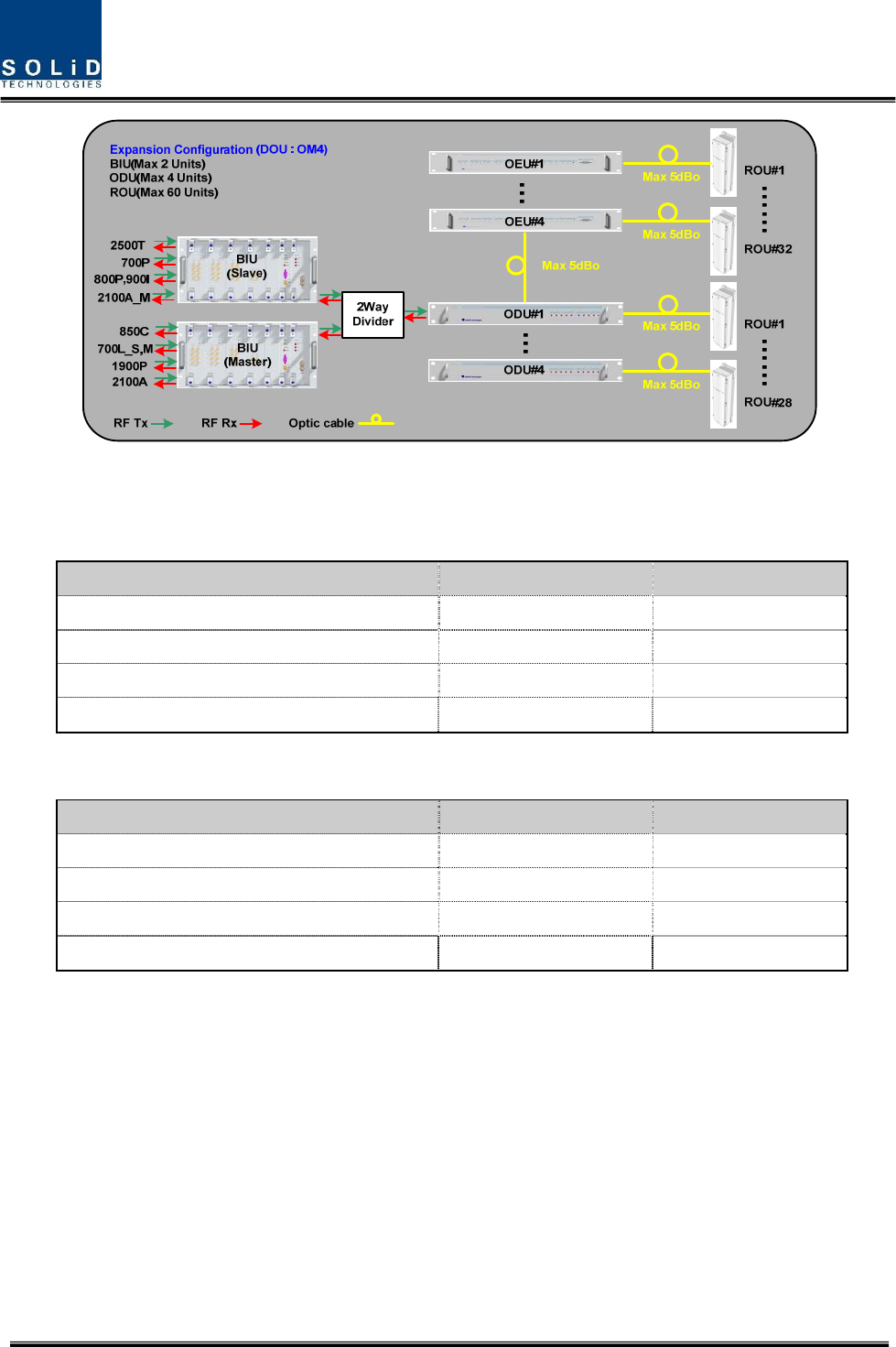
Figure2.Expansionsystemtopology
SystemtopologyCharts(OM4;4Opticalport)
SystemelementsOpticalLoss[dBo]Max.RUs
BIU–ODU(DOUx1)–ROU 1~5dBo4
BIU–ODU(DOUx2)–ROU1~5dBo8
BIU–4ODU(DOUx2)–ROU1~5dBo32
BIU–4ODU(DOUx2)‐4OEU(DOUx2)–ROU1~5dBo60
SystemtopologyCharts(OM1;1Opticalport)
SystemelementsOpticalLoss[dBo]Max.RUs
BIU–ODU(DOUx1)–ROU 1~10dBo1
BIU–ODU(DOUx2)–ROU1~10dBo2
BIU–4ODU(DOUx2)–ROU1~10dBo8
BIU–4ODU(DOUx2)‐4OEU(DOUx2)–ROU1~10dBo12

Confidential & Proprietary 14/44
Section3
SystemconfigurationandFunctions
3.1HROU(HighpowerRemoteOpticUnit)
3.1 HROU(HighpowerRemoteOpticUnit)
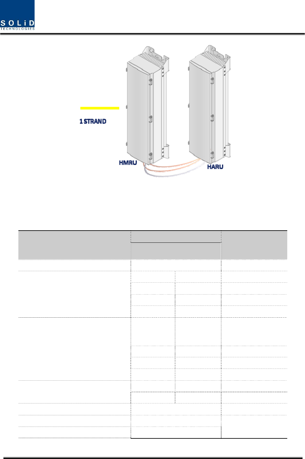
HROUconsistsoftwounit,oneisHMRU(HighpowerMainRemoteUnit)andtheotherisHARU(High
powerAdd‐onRemoteUnit).
ThebiggestdifferencebetweenHMRUandHARUiswhetherR‐OPTICmoduleexistornotinthe
enclosure.
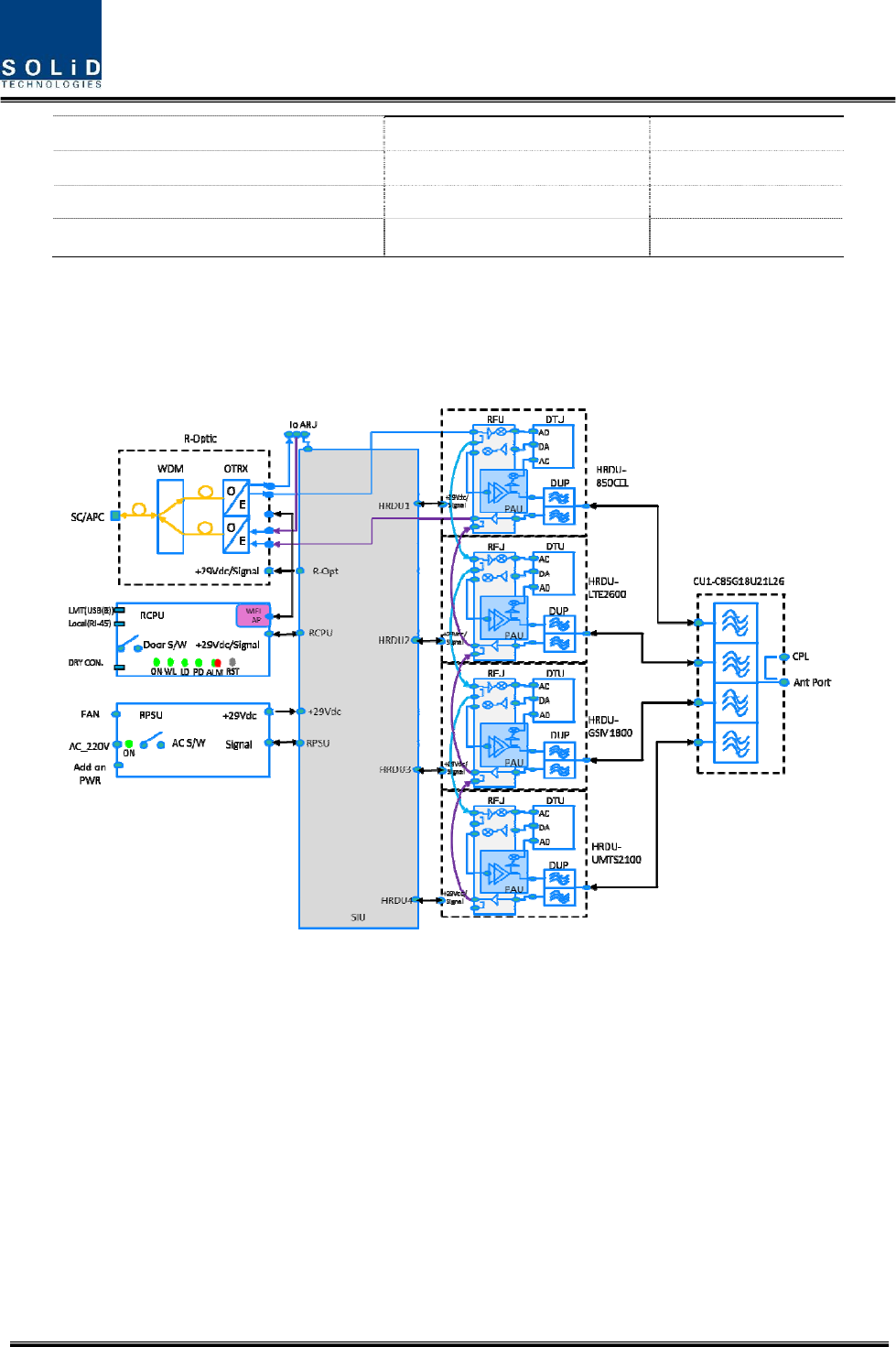
HMRUreceivesTXopticalsignalsfromODUandconvertsthemintoRFsignals.TheconvertedRFsignals
areamplifiedthroughHighPowerAmpinacorrespondingHRDUbandcombinedwithUDCU,PAUand
Cavityduplexer,andthenradiatedtotheantennaport.
WhenreceivingRXsignalsthroughtheantennaport,thisunitfiltersout‐of‐bandsignalsina
correspondingHRDUandsendstheresultstoR‐OPTICtomakeelectronic‐opticalconversionofthem.
Afterconverted,thesignalsaresenttoaupperdeviceofODU.HMRUcanbeequippedwithuptofour
HRDUs(HighRemoteDriveUnit)andthemodulesupportssinglebandonly.
HARUreceivesTXRFsignalfromHMRUandamplifiesthroughHighPowerAmpinacorresponding
HRDUcombinedwithUDCU,PAUandCavityduplexer,andthenradiatedtotheCU(CombiningUnit)
WhenreceivingRXsignalsthroughtheantennaport,HHRDUfiltersout‐ofbandsignalina
correspondingHRDUandsendstheresultstoMHRUthroughRFcable.
Confidential & Proprietary 15/44
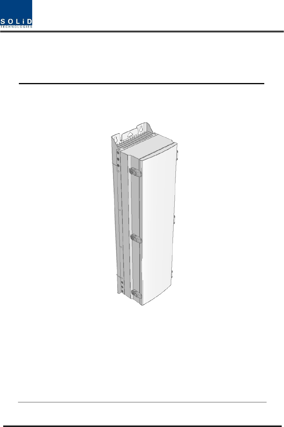
Figure3.HROUouterLook
3.1.1 SpecificationsofHROU
Item
Spec.
Remark
HMRU
TheratedmeanoutputPowerperband 44dBm 25Wperband
The nominal downlinkbandwidth
LTE70028MHz728~756MHz
850IC32MHz862‐894MHz
1900P65MHz1930‐1995MHz
2100A45MHz2110‐2155MHz
The nominal uplinkbandwidth
LTE700
17MHzand
10MHz
699~716MHz
777~787MHz
850IC32MHz817‐849MHz
1900P65MHz1850‐1915MHz
2100A45MHz1710‐1755MHz
Thenominalpassbandgain
Downlink59dBeachband
Uplink45dBeachband
Input/OutputImpedance 50ohm
Weight39Kg
CommonPart
Powerconsumption50W
Confidential & Proprietary 16/44
Temperaturerange‐25°Cto+55°C/‐13to131°FAmbientTemperature
HumidityRange0%~90%Non‐condensing
Sealing(RemoteUnit)IEC60529EN60529IP66Complaint
Size(mm)320x1165x260IncludingBracket
3.1.2 BlockDiagramofHROU
3.1.2.1 HMRUblockdiagram
Figure4.HMRUBlockdiagram
Confidential & Proprietary 17/44
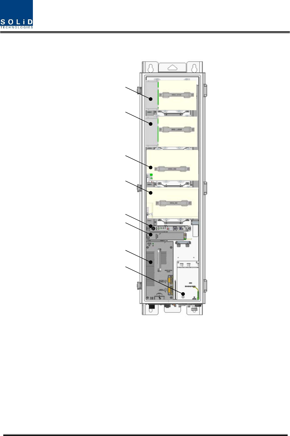
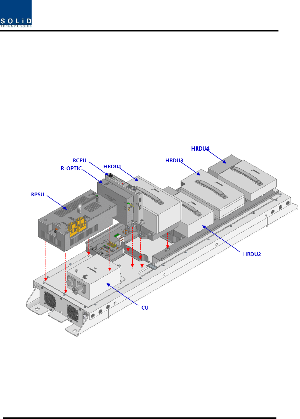
3.1.2.2 HROUinnerlook
HRDU#4
HRDU#3
HRDU#2
HRDU#1
R-OPTIC
RPSU
CU
RCPU
Figure5.InsideofRemoteUnit

Confidential & Proprietary 18/44
3.1.2.3 HROUpartlist
No.UnitDescriptionRemark
1HRDUX4
HighRemoteDriveUnit
ConsistofUDCU,PAUandcavityfilter
FilterandhighamplifyTXsignals;
FilterandamplifyRXsignalsinlownoiseamplifier;
Removeout‐ofsignalsthroughcavityduplexer
Optional
Max4
2
RPSU(AC)
RemotePowerSupplyUnit
Inputpower:110VAC/220VAC(85~264V)
Outputpower:+29VDC
RPSU(DC)
RemotePowerSupplyUnit
Inputpower:‐48VDC(‐40.8~‐57.6V)
Outputpower:+29VDC
3R‐OPTIC
RemoteOptic
MakeRFconversionofTXopticalsignals;
ConvertRXRFsignalsintoopticalsignals;
Compensatesopticalloss;
5dBoopticallinkbetweenODU(OM4)andROU;
10dBoopticallinkbetweenODU(OM1)andROU;
FiberConnector:SC/APCConnector;
OpticalWavelength:1310/1550WDM;
CommunicateswithBIU/OEUthoughtheFSKmodem
4RCPU
RemoteCentralProcessorUnit
Controlssignalofeachunit
MonitorsBIU/ODU/OEUstatusthroughFSKmodem
communication
5
CU_1A70851921
Multiplexer1
CombineTXsignalsfrom4HRDUs;DistributeRXsignalsto
4HRDUs
CU_2A70851921
Multiplexer2
CombineTXsignalsfrom2HRDU;DistributeRXsignalsto
2HRDUsoflowfrequencyunder1GHz
CombineTXsignalsfrom2HRDUs;DistributeRXsignalsto
2HRDUsofhighfrequencyover1GHz
Confidential & Proprietary 19/44
6Enclosure
EnclosuretosatisfyNEMA4(IP66);
Wallmounting(VerticalMount)
7SIU
SystemInterfaceUnit
Distributepowerandsignalsofeachmodule
3.1.3 Functionbyunit
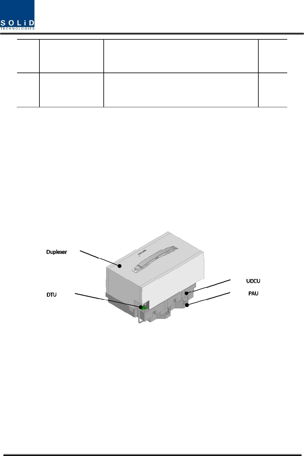
3.1.3.1 HighRemoteDriveUnit(HRDU)
WhenreceivingTXsignalsfromeachbandthroughRemoteOptic,HRDUfiltersthesignalsandamplifies
themwithHighPowerAmpifier.TheunitalsofiltersRXsignalsgiventhroughcavityfilterandamplifies
themtosendthesignalstoRemoteOptic.Intheunit,thereisATTtoadjustgain.HRDUconsistofUDCU,
DTU,PAUandcavityduplexerlikebelowfigureandallmodulesaremergedwithonepackage
Figure6.HRDUOuterLook
Confidential & Proprietary 20/44
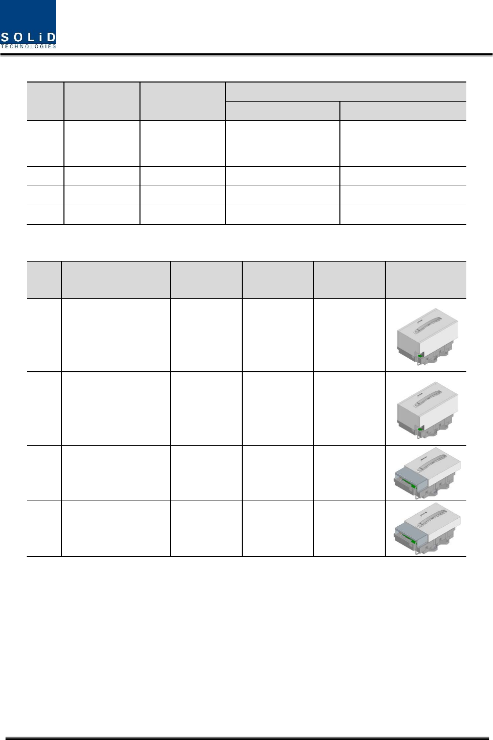
HRDUdevicesarevariedforeachfrequencyband,includingthefollowing:
NoUnitnamingDescription
Frequency(Bandwidth)
TXRX
1N20‐HRDU‐L700Singleband728~756MHz
699~716MHz
777~787MHz
2N20‐HRDU‐850ICSingleband862‐894MHz 817‐849MHz
3N20‐HRDU‐1900PSingleband1930‐1995MHz1850‐1915MHz
4N20‐HRDU‐2100ASingleband2110‐2155MHz 1710‐1755MHz
NoUnitnamingDimensionWeight
Power
consumption
Outlook
1N20‐HRDU‐L700233X155X148 6.2kg140W
2N20‐HRDU‐850IC233X155X143 5.6kg150W
3N20‐HRDU‐1900P233X155X131 4.5kg150W
4N20‐HRDU‐2100A233X155X983.4kg130W
Confidential & Proprietary 21/44
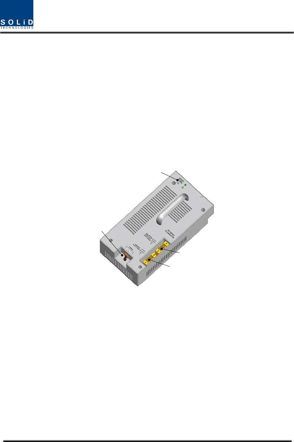
3.1.3.2 RemotePowerSupplyUnit(RPSU)
Thereare2typesofRPSUintheHROUforsupplytoactivemoduleintheenclosureandreceivepower
fromexternal.
TheyaretheDC/DCPSUreceivinginput‐48VandtheAC/DCPSUreceivinginput110V/220Vfrom
external.
Asorder,eitherofthetwotypesshouldbedecided.MSConnector,whichusesportstoreceiveinputs,
isdesignedtoacceptanyofACandDC.Onlyinthiscase,theinputcableisdifferent
RPSUhasacircuitbraketoturnthepowerON/OFFandhasLEDindicatoratthetoptocheckifinput
powerisnormallysupplied.
POWER SWITCH
FAN CON
POWER IN
ADD-ON ROU
POWER OUT
Figure7.AC‐DCRPSUOuterLook
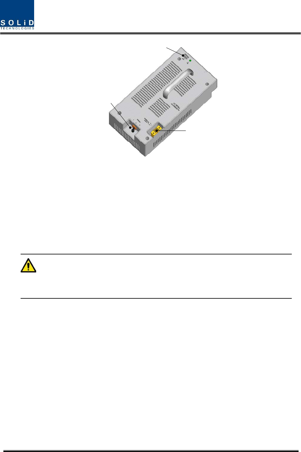
Confidential & Proprietary 22/44
POWER IN
POWER SWITCH
FAN CON
Figure8.DC‐DCRPSUOuterLook
Functions:
ProvidingacircuitbreakertoturnACpowerON/OFF
ProvidingDCpowereachHRDU
ProvidingDCpowerandsignaltoFANtray
LEDindicatorsforshowingalarmstausofPSU
Caution
DOUBLEPOLE/NEUTRALFUSING
3.1.3.3 RemoteOptic(ROPTIC)
RemoteOpticconvertsopticalsignalsintoRFsignalsandperformsviceversa.ItalsohasinternalATTfor
opticalcompensationtocompensateforopticalcableloss.Itprovidestwopathinpairs(TX/RX)to
transportRFsignaltoARUs
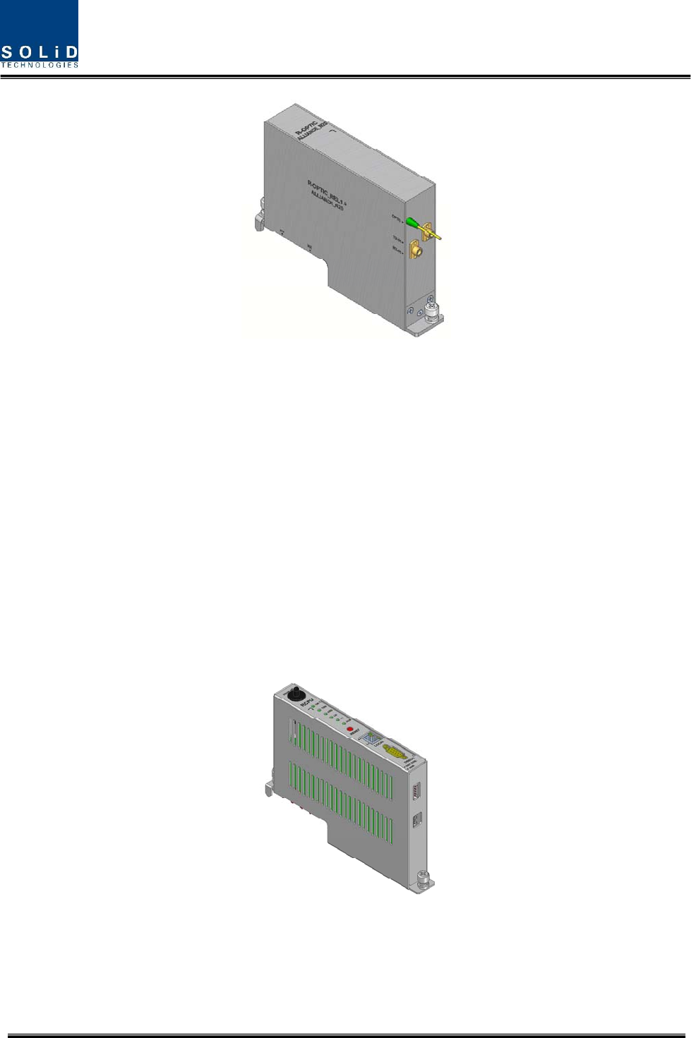
Confidential & Proprietary 23/44
Figure9.ROPTICOuterLook
3.1.3.4 RemoteCentralProcessorUnit(RCPU)
RCPUcanmonitorandcontroleachmoduleofHROU.Thisunitreceivesandanalyzesupper
communicationdatafromRemoteOpticandreportstheunit'sownvaluetoupperdevices.Atthefront
ofthemodule,ithasLEDindicatortoshowsystemstatus,lettingyoucheckanyabnormalitiesatatime.
Atthesamefront,italsohascommunicationLEDIndicatorstoshowcommunicationstatuswithupper
devices.ThroughLocalport,theunitenablesyoutocheckandcontroldevicestatusthroughPCand
laptop.
ItprovidesthreeinterfaceportwithARUstocommunicatewiththese.Italsoprovidedrycontactport,
whichis(1)outputportand(1)inputport
Figure10.RCPUOuterLook
Confidential & Proprietary 24/44
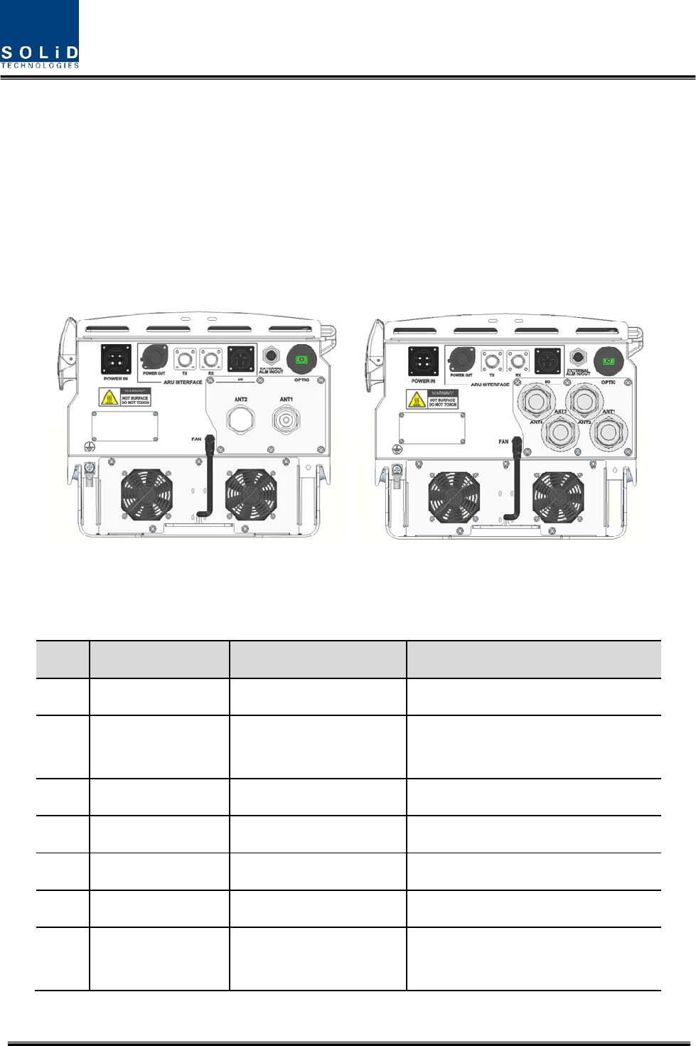
3.1.4 BottomofHROU
3.1.4.1 Functions
TheBottomlookofHROUdependsontheCU(combineunit)option.Basically,TheCUhastwo
antennaports.
But,IfnotneedtoinstallCUintheenclosure,ThenumberofantennaportsonthebottomofHROUwill
bechange4portswithDIN‐type.
Figure11.TheBottomLookofHROU
NoPortHMRURemark
1OpticalPort1EASC/APC,Waterproof
2 ARUInterface
1EA,
(1)CON,(2)SMA‐Female
3ANT11EADIN‐typefemale
4ANT21EADIN‐typefemale
5ANT31EADIN‐typefemale
6ANT41EADIN‐typefemale
7
ACPowerIN
OrDCPowerIN
1EAMS‐Con,Waterproof

Confidential & Proprietary 25/44
8ACPowerOUT1EAMS‐Con,Waterproof
9EXT‐FAN1EAWaterproof‐Con

Confidential & Proprietary 26/44
Section4
SystemInstallation
4.1 HROUInstallation
Thischapterdescribeshowtoinstalleachunitandopticalcables,alongwithpowercablingmethod.
Indetail,thechapterdescribeshowtoinstallshelvesorenclosuersofeachunit,PowerCablingmethod
andOpticCablingandRFInterface.Furthermore,byshowingpowerconsumptionofmodulestobe
installedineachunit,itpresentsPowerCablingbudgetinasimpleway.Then,itdescribesthequantity
ofcomponentsofmodulestobeinstalledineachunitandexpansionmethod.
Confidential & Proprietary 27/44
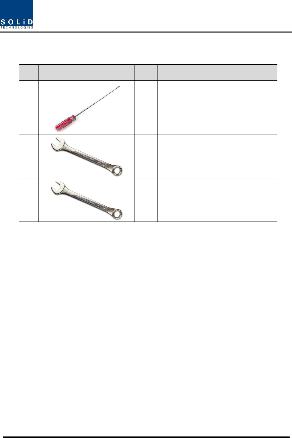
4.1.1 Tools
Toolsneededforinstallationistablebelow
NoToolsQ’tySpecificationRemark
1
1
+,3Ø
Lengthismorethan20mm
Forfixing
HRDU
2
133mm
Totighten
antennaport
3
119mm
ToCUN‐type
port
4.1.2 HROUEnclosureinstallation
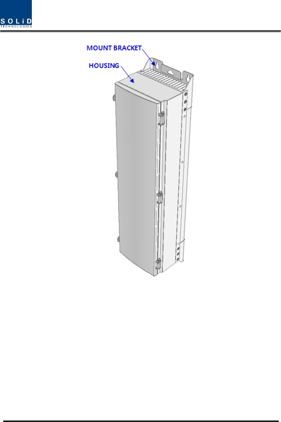
HROUisdesignedtobewater‐ anddirt‐proof.Theunithasthestructureofone‐Bodyenclosure.It
satisfieswater‐proofandquake‐proofstandardsequivalentofNEMA4(IP65).Thewaytoinstallforboth
HMRUandARUhassamemethod.BasicallyHROUisattachedwithwallmountablebracket.HROUcan
bemountedintoeitherofwalloronapole.
Confidential & Proprietary 28/44
Figure12.HowtoinstallROU
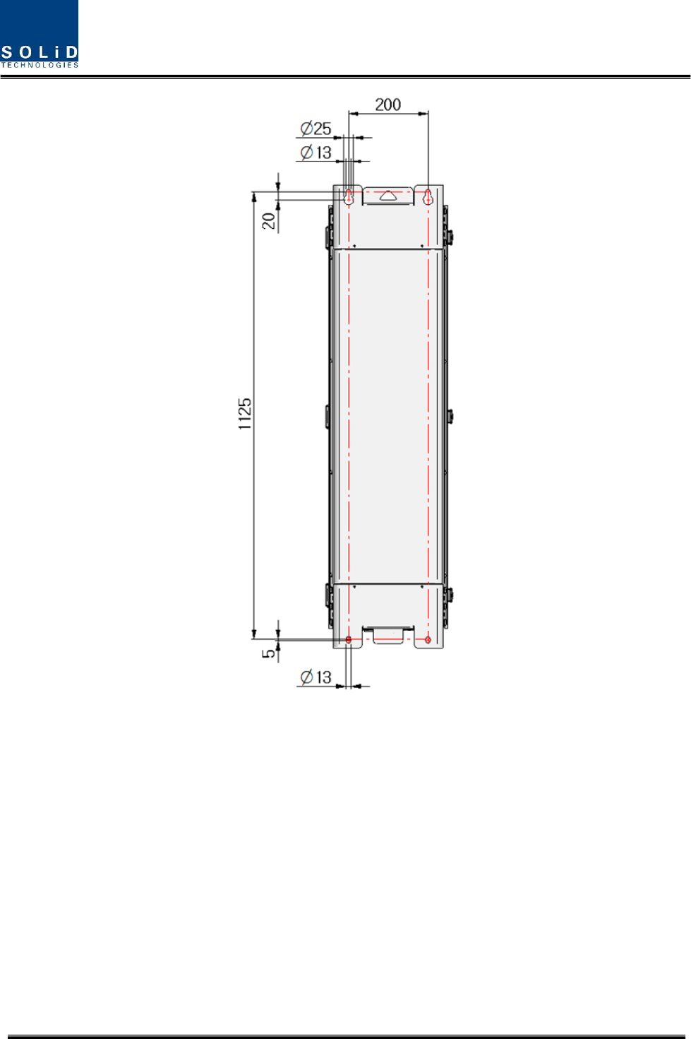
Confidential & Proprietary 29/44
Figure13.DimensionusedtoinstallHROUontheWALL
4.1.3 HROUWallMountInstallation
HROU’sinstallationbracketisattachedonEnclosurewhenisdelivered.Itdoesn’tneedtoremove
brackettoinstallenclosure.simplyafterinstalling4ofM12mountingbolts,secure4mountingbolts
tightly
First,install2ofM12mountingboltsroughlyhalfwayontheenclosureandinstallenclosureoverthe
boltsandsecuretightly.
Second,install2ofM12mountingboltsundertheenclosureandsecuretightly
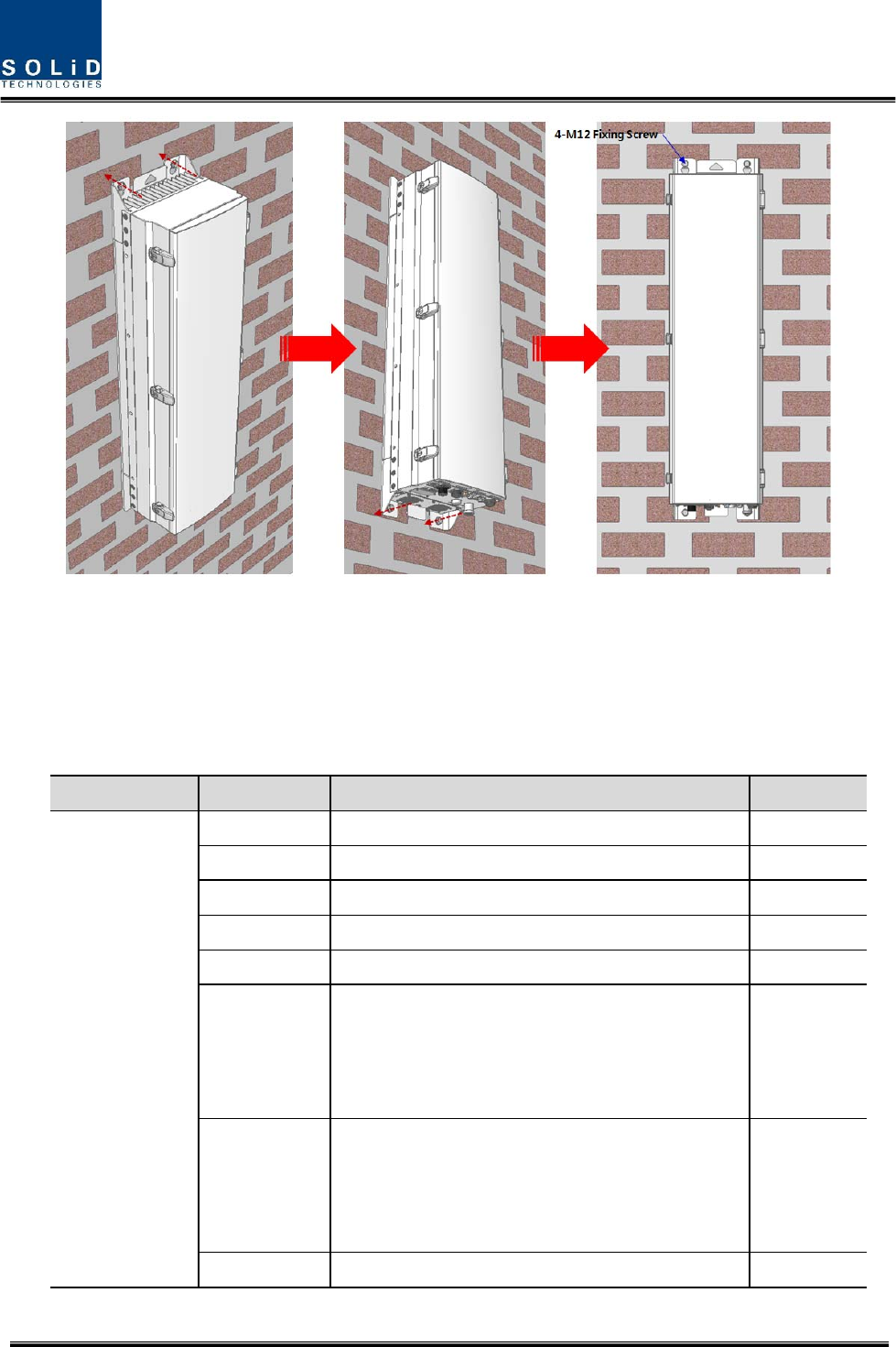
Confidential & Proprietary 30/44
Figure14.Proceduresofinstallation
4.1.4 HROUcomponents
HROUhasthefollowingcomponents:
No.UnitDescriptionRemark
CommonPart
EnclosureIncludingWallmountingbracket1EA
RCPU‐ 1EA
R_OPTICWithSC/ACPadaptor(onlyHMRU)1EA,optional
RPSUAC110/220VorDC‐48V1EA
FANUNIT2FANsisinside1EA
CU_1
CombineTXsignalsfrom5HRDUs;DistributeRX
signalsto5HRDUs;
Furthermore,thereisreservedHRDUslottosupport
2600LTE
ANT1
CU_2
CombineTXsignalsfrom2HRDU;DistributeRX
signalsto2HRDUsoflowfrequencyunder1GHz
CombineTXsignalsfrom2HRDUs;DistributeRX
signalsto2HRDUsofhighfrequencyover1GHz
ANT1and
ANT2
PowerCable1‐MSConnectorwith4hole(ACandDC)1EA,HMRU

Confidential & Proprietary 31/44
PowerCable2
‐ MSconnectorforHMRUconnectionwithMScon
andCircularconnectorontheeachsideofend
1EA,HARU
HMRUHRDU
Basically,thecommonpartofHROUshouldhaveanenclosureanditisequippedwithRCPUtoinquire
andcontrolstateofeachmodule,R_OPTICtomakebothofelectronic‐opticalandoptical‐electronic
conversions,RPSUtosupplypowerforHROU.ItshouldhavePowerCableforexternalrectifierorto
supplyrequiredpower.
Inaddition,HRDUcanbemountedandremovedtoprovideservicefordesiredband.
Confidential & Proprietary 32/44
4.1.5 HROUPowerCabling
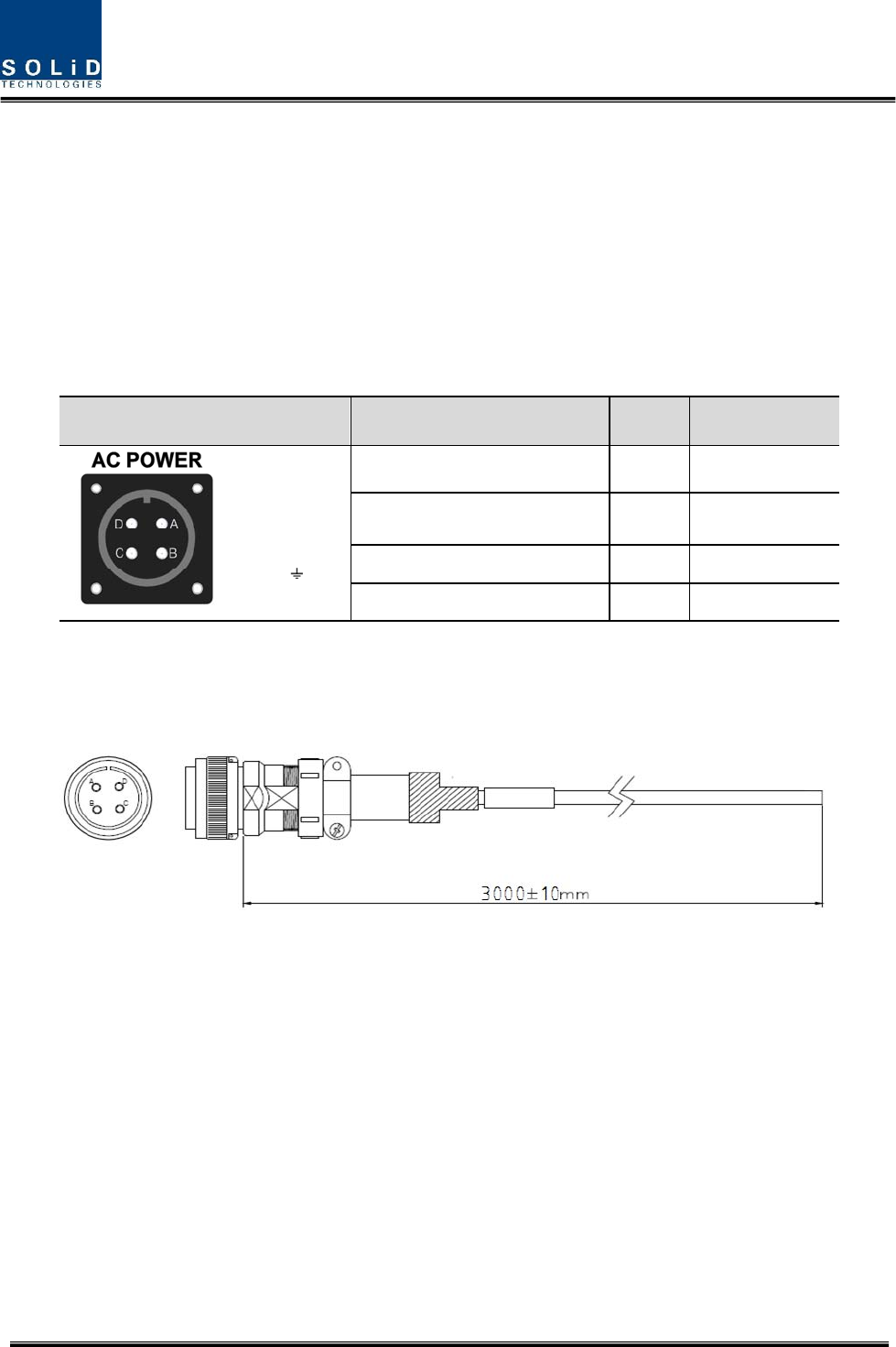
ACPower
HROUsupportsAC110V/220Vofinputpower.Providedoutsidepowercableisonlyonetypewith
AWG#143m.Powercableisprovidedwithoutpowerpluganditshouldbeattachedpowerplugbased
onnational’spowerplugtype
ThepindiscriptionofACportisbelow.YoushouldconnectexactpolarityofAC.
PortoutlookMSConnectornumberingNameDescription
A : AC_H
B : AC_N
C : N.C
D : F.G
AAC_HACHot
BAC_NACNeutral
CN.CNotConnected
DF.GFrameGround
CheckiftheconnectionisthesameasoneseeninthetableaboveandmakesuretoturnthepowerON.
ProvidedACpowercable’soutlookisbelow
Confidential & Proprietary 33/44
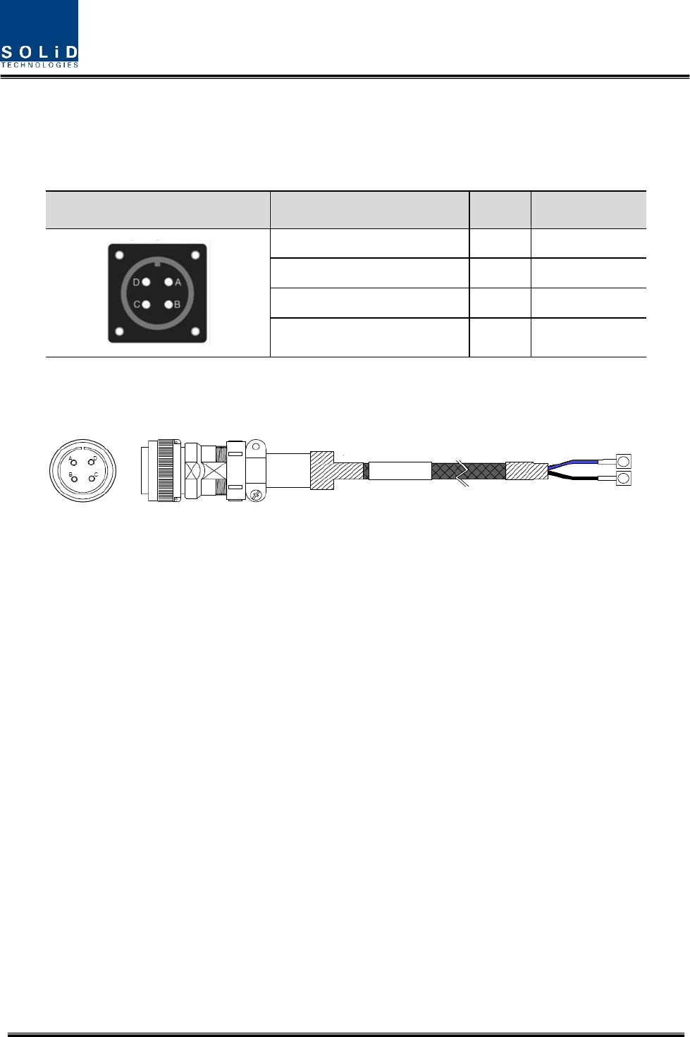
DCPower
HROUsupportsonlyDC48Vofinputpower.Providedoutsidepowercableisonlyonetype.Thepin
discriptionofDCportisbelow.YoushouldconnectexactpolarityofDC.
PortoutlookMSConnectornumberingNameDescription
AN.CNotConnected
BN.CNotConnected
C+V+48V
D‐V‐48V
CheckiftheconnectionisthesameasoneseeninthetableaboveandmakesuretoturnthepowerON.
ProvidedDCpowercable’soutlookisbelow
Confidential & Proprietary 34/44
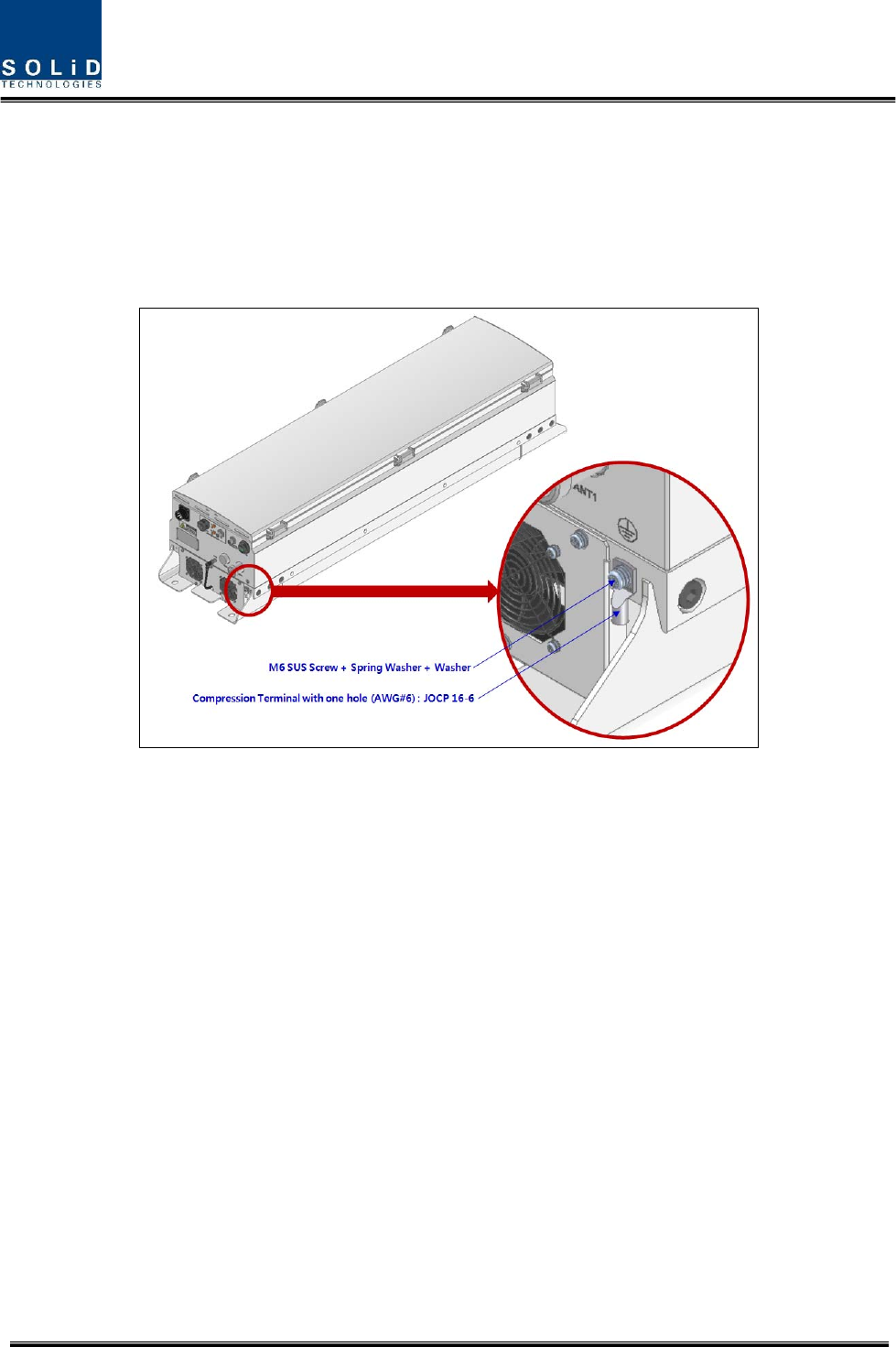
4.1.6 HROUGroundcabling
TheGroundingterminalislocatedatthebottomofHROUenclosurefixedbyM6screw.Compression
terminalisattachedalreadywhenisdelivered.TherecommendedthicknessofcableisAWG#6copper
groundingwire
Figure15.LocationofGroundTerminal
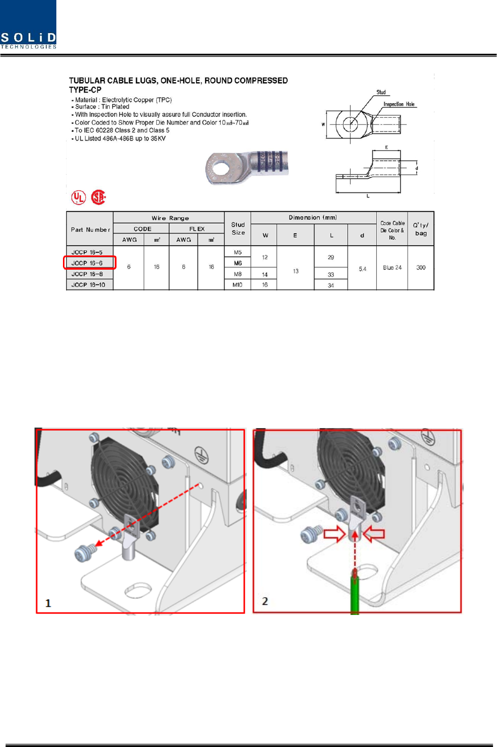
Thespecificationofcompressionterminalislikebelow
Confidential & Proprietary 35/44
Figure16.InformationofTerminal
TherequiredpartnumberisJOCT16‐6supportingAWG6.Thewaytoinstallthegroundingcable
complywithbelowprocedures
Confidential & Proprietary 36/44
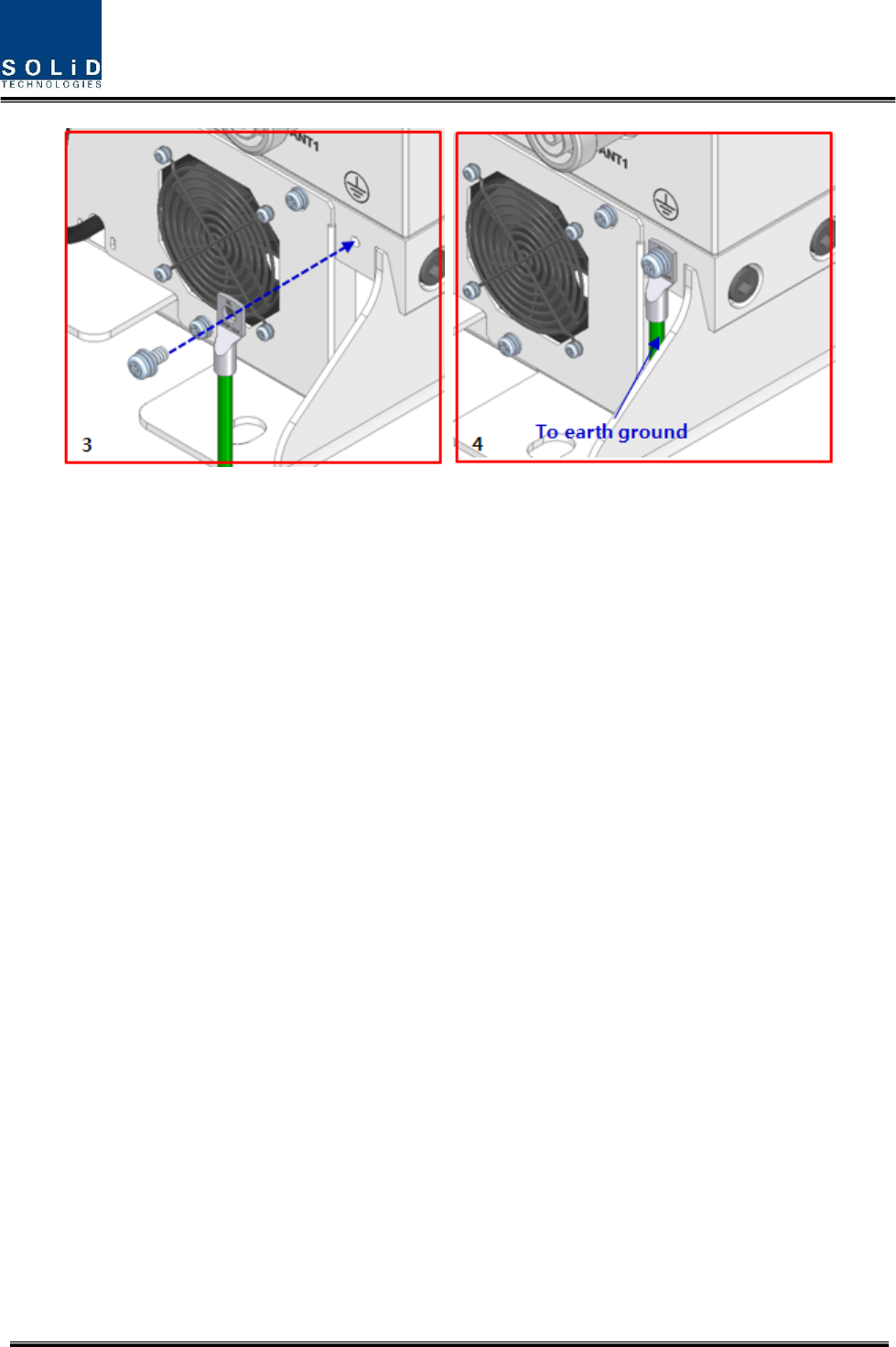
Figure17.HowtoinstallGroundTerminal
Theproceduresare
1. LoosenatwoM6screwsandthentakecompressionterminaloff
2. InsertAWG#6GroundingWireintoterminalandthencompressaterminalusingtool
3. Assembletheterminalwhichmadeinstep“2”using2xM6screws
4. Cutthegroundwiretoproperlengthandconnectittotheearthgroundsource
(Roundterminalslocatedonthesideofa1mm2(16AWG)ormorewiresUsingpermanently
connectedtoearth.)
4.1.7 HROUOpticalcabling
TheOpticalConnectorislocatedatthebottomofRemoteUnitenclosurefixed.OpticalCablecanbe
connectedbyusingconnectors.
Confidential & Proprietary 37/44
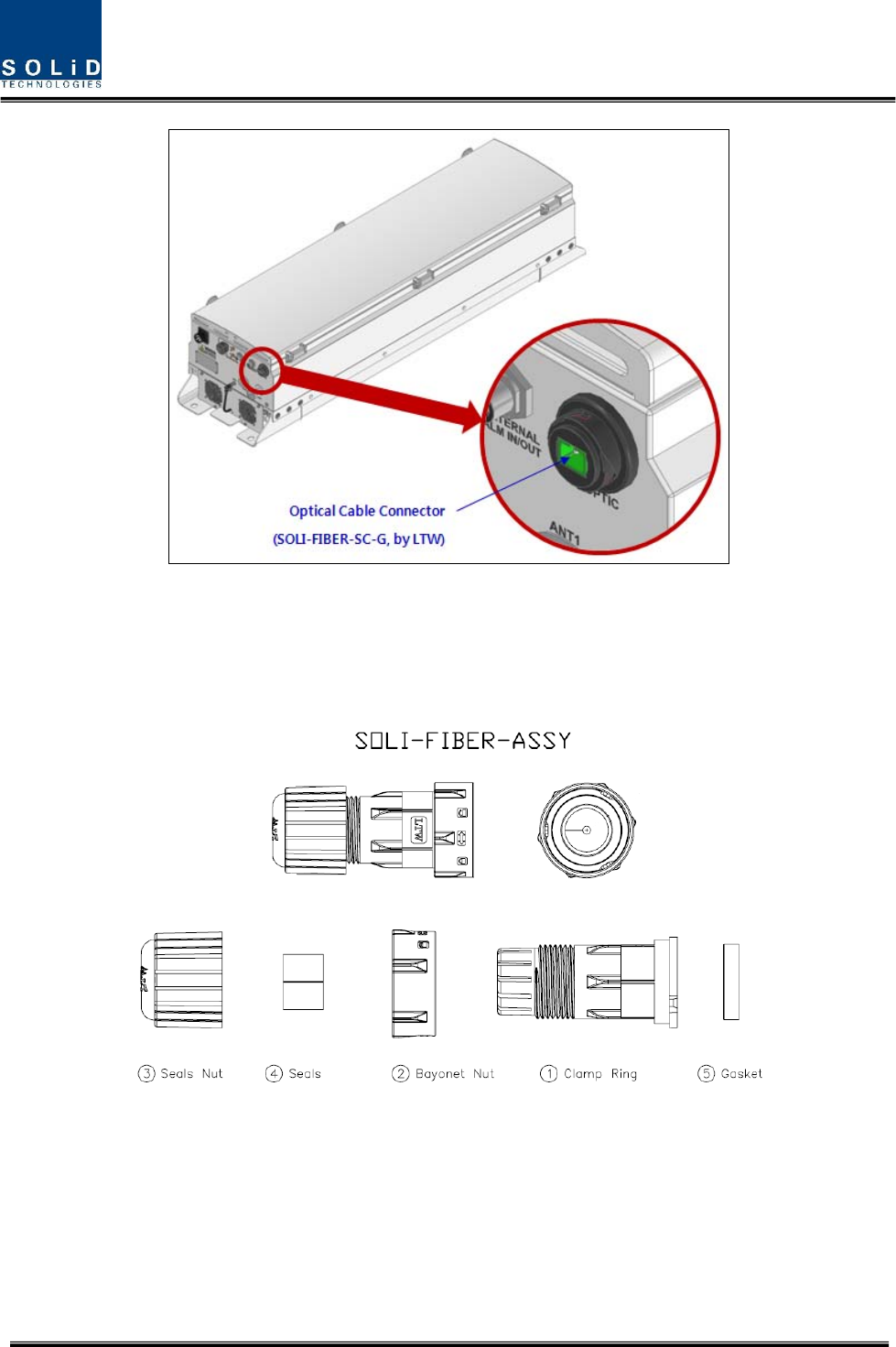
Figure18.LocationofOpticalConnector
ThespecificationofcompressionOpticConnectorislikebelow
Figure19.InformationofOpticalConnector
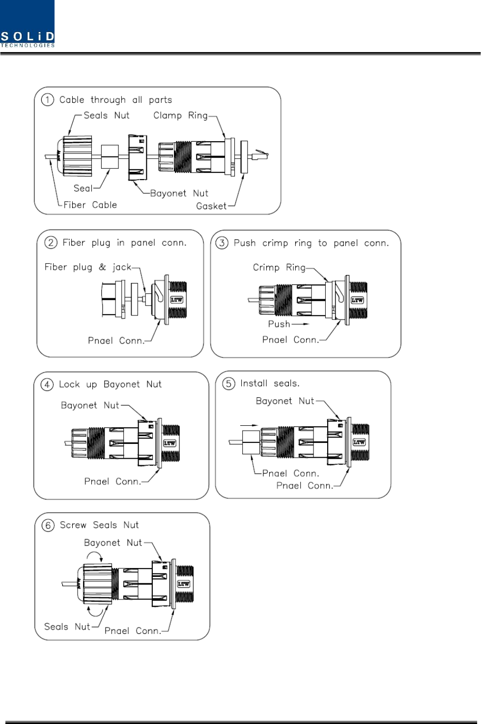
ThewaytoinstalltheOpticalcablecomplywithbelowprocedures
Theproceduresare
Confidential & Proprietary 38/44
Figure20.HowtoinstallOpticalCabling
Confidential & Proprietary 39/44
4.1.8 HROUALMIN/OUTPortcabling
TheALMIN/OUTConnectorislocatedatthebottomofRemoteUnitenclosurefixed.Cablecan
beconnectedbyusingconnectors.
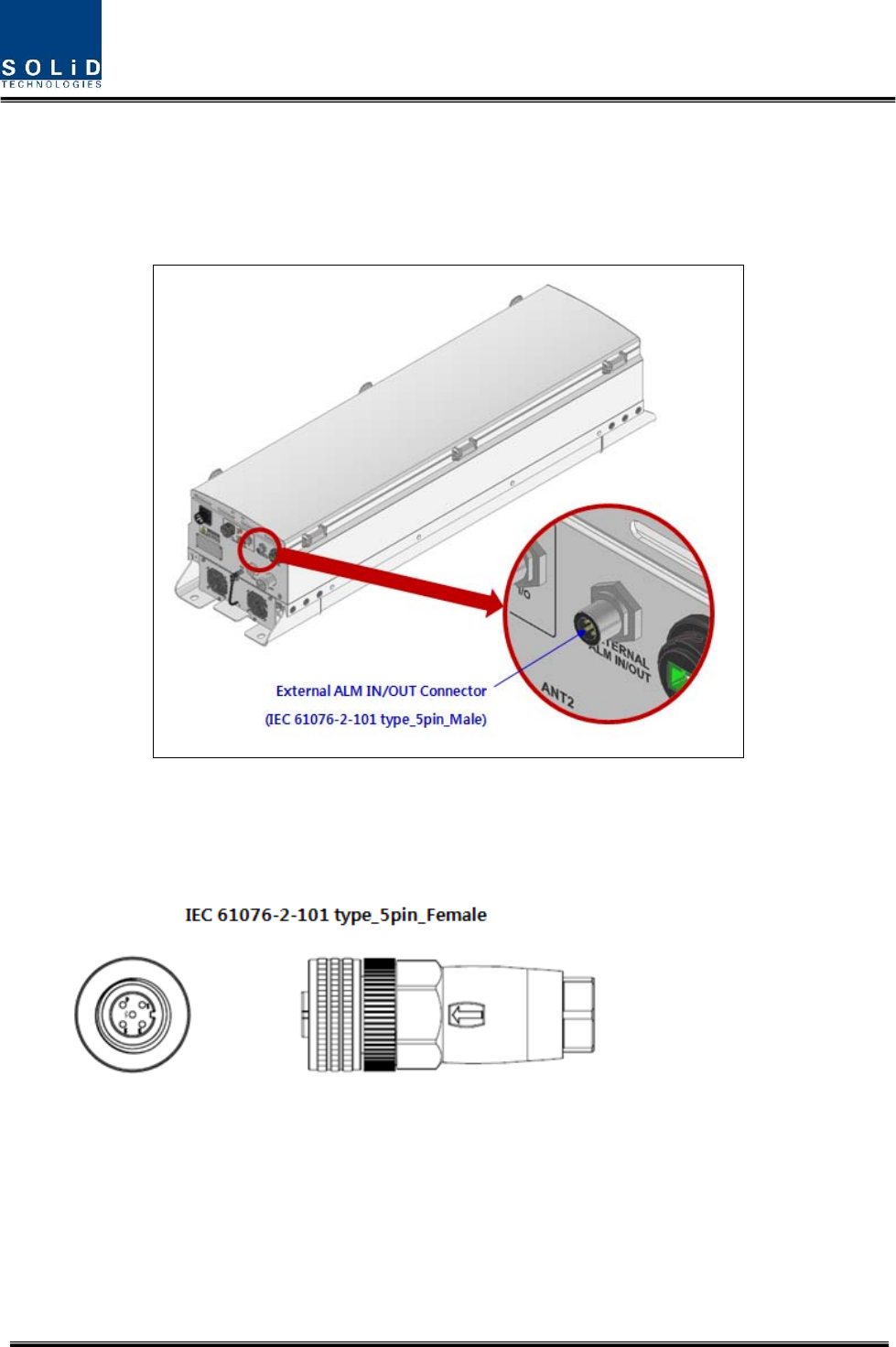
Figure21.LocationofALMIN/OUTConnector
ThespecificationofcompressionALMIN/OUTConnectorislikebelow
Figure22.InformationofALMIN/OUTConnector
Confidential & Proprietary 40/44
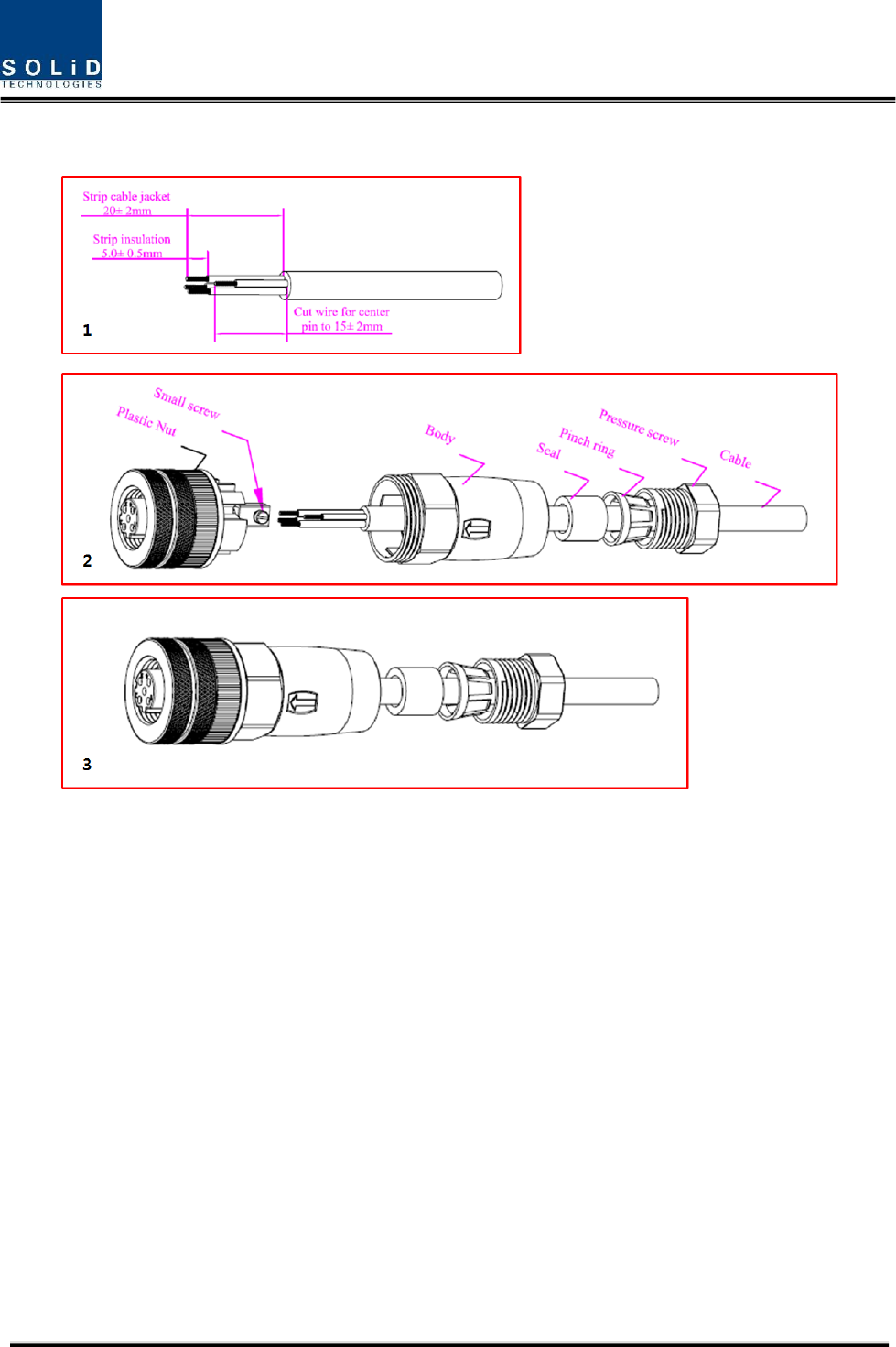
ThewaytoinstalltheALMIN/OUTConnectorcomplywithbelowprocedures
Figure23.HowtoinstallALMIN/OUTCabling
Theproceduresare
Peeloffsheathofthecable.
Assembleallcomponentsoncableasfollowing.
Connectallwirestoinsertaccordingtowirelist,thentightenallsmallscrews.
Thetorqueforsmallscrewsis0.2Nm.
Assembleplasticnuttomainbody.Recommendedtorque:1.0Nm.
(Note:Thekeyinsidethemainbodymustgostraighttoslotofinsert.)
Pushthecableseal,pinchringintothemainbody,thentightenthepressurescrewintothebodywith
recommendedtorque:1.0Nm.
Confidential & Proprietary 41/44
4.1.9 MountingofHRDU
HROUhasslotstoenableuptofourHRDUmodulestobemountedinit.
YoucanmountaHRDUintodesignatedslotsurely.Itisnotpossibletoprovideserviceswitha
HRDUmodulealone;youneedtoconnectHRDUcavityduplexerantennaportwithCU’s
designatedport.
Figure24.HowtomountHRDU
TheRemoteUnitholdsamaximumof4HRDUs.GuidebracketsonthebottomofeachHRDUslot
simplifyinstallationasdescribedbelow.MRDUinstallationrequiresa+No.1tipsizescrewdriver.
Confidential & Proprietary 42/44
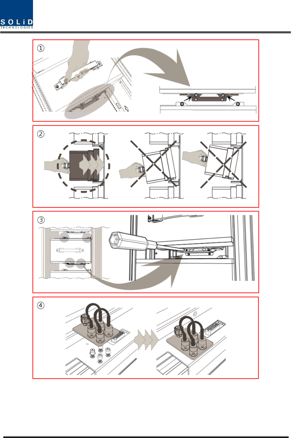
Figure25.HowtomountHRDU

Confidential & Proprietary 43/44
Theproceduresare
1. LifttheHRDUontotheguidebracketandensuretheMRDUislevellefttoright
2. PushtheHRDUintothecorrespondingslotinthedirectionoftheheatsinkwhilelevellingthe
MRDUtoguidebracket
3. MakesuretheHRDUisfirmlyinsertedintothecorrespondingslot.Tightenthe4cornerscrews
tosecuretheunit
4. InstallHRDUblankcardsinallunusedslotsintheremote.Firstinserttheblankcardintothe
correspondingslot,thentightenthecaptivescrewtosecureit
"TheManufacturer'sratedoutputpowerofthisequipmentisforsinglecarrieroperation.For
situationswhenmultiplecarriersignalsarepresent,theratingwouldhavetobereducedby3.5
dB,especiallywheretheoutputsignalisre‐radiatedandcancauseinterferencetoadjacent
bandusers.Thispowerreductionistobebymeansofinputpowerorgainreductionandnot
byanattenuatorattheoutputofthedevice."
RSS‐GEN,Sec.7.1.2–(transmitters)
UnderIndustryCanadaregulations,thisradiotransmittermayonlyoperateusinganantenna
ofatypeandmaximum(orlesser)gainapprovedforthetransmitterbyIndustryCanada.To
reducepotentialradiointerferencetootherusers,theantennatypeanditsgainshouldbeso
chosenthattheequivalentisotropicallyradiatedpower(e.i.r.p.)isnotmorethanthat
necessaryforsuccessfulcommunication.
Conformémentàlaréglementationd’IndustrieCanada,leprésentémetteurradiopeut
fonctionneravecuneantenned’untypeetd’ungainmaximal(ouinférieur)approuvépour
l’émetteurparIndustrieCanada.Danslebutderéduirelesrisquesdebrouillageradioélectrique
àl’intentiondesautresutilisateurs,ilfautchoisirletyped’antenneetsongaindesortequela
puissanceisotroperayonnéequivalente(p.i.r.e.)nedépassepasl’intensiténécessaireà
l’établissementd’unecommunicationsatisfaisante.

Confidential & Proprietary 44/44
RSS‐GEN,Sec.7.1.2–(detachableantennas)
Thisradiotransmitter(identifythedevicebycertificationnumber,ormodelnumberif
CategoryII)hasbeenapprovedbyIndustryCanadatooperatewiththeantennatypeslisted
belowwiththemaximumpermissiblegainandrequiredantennaimpedanceforeachantenna
typeindicated.Antennatypesnotincludedinthislist,havingagaingreaterthanthemaximum
gainindicatedforthattype,arestrictlyprohibitedforusewiththisdevice.
Leprésentémetteurradio(identifierledispositifparsonnumérodecertificationouson
numérodemodèles’ilfaitpartiedumatérieldecatégorieI)aétéapprouvéparIndustrie
Canadapourfonctionneraveclestypesd’antenneénumérésci‐dessousetayantungain
admissiblemaximaletl’impédancerequisepourchaquetyped’antenne.Lestypesd’antenne
noninclusdanscetteliste,oudontlegainestsupérieuraugainmaximalindiqué,sont
strictementinterditspourl’exploitationdel’émetteur.
RFRadiationExposure
ThisequipmentcomplieswithRFradiationexposurelimitssetforthforanuncontrolled
environment.Thisequipmentshouldbeinstalledandoperatedwithaminimumdistanceof
500cmbetweentheradiatorandyourbody.Thistransmittermustnotbeco‐locatedor
operatinginconjunctionwithanyotherantennaortransmitter.RFexposurewillbeaddressed
attimeofinstallationandtheuseofhighergainantennasmayrequirelargerseparation
distances.
RSS‐102RFExposure
L’antenne(oulesantennes)doitêtreinstalléedefaçonàmainteniràtoutinstantunedistance
minimumdeaumoins500cmentrelasourcederadiation(l’antenne)ettoutepersonne
physique.Cetappareilnedoitpasêtreinstalléouutiliséenconjonctionavecuneautreantenne
ouémetteur.