SOLiD NHRAWS13 ALLIANCE_N20 User Manual MB DAS

SOLiD, Inc. ALLIANCE_N20 MB DAS

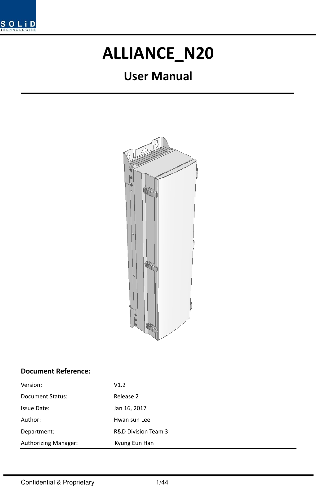
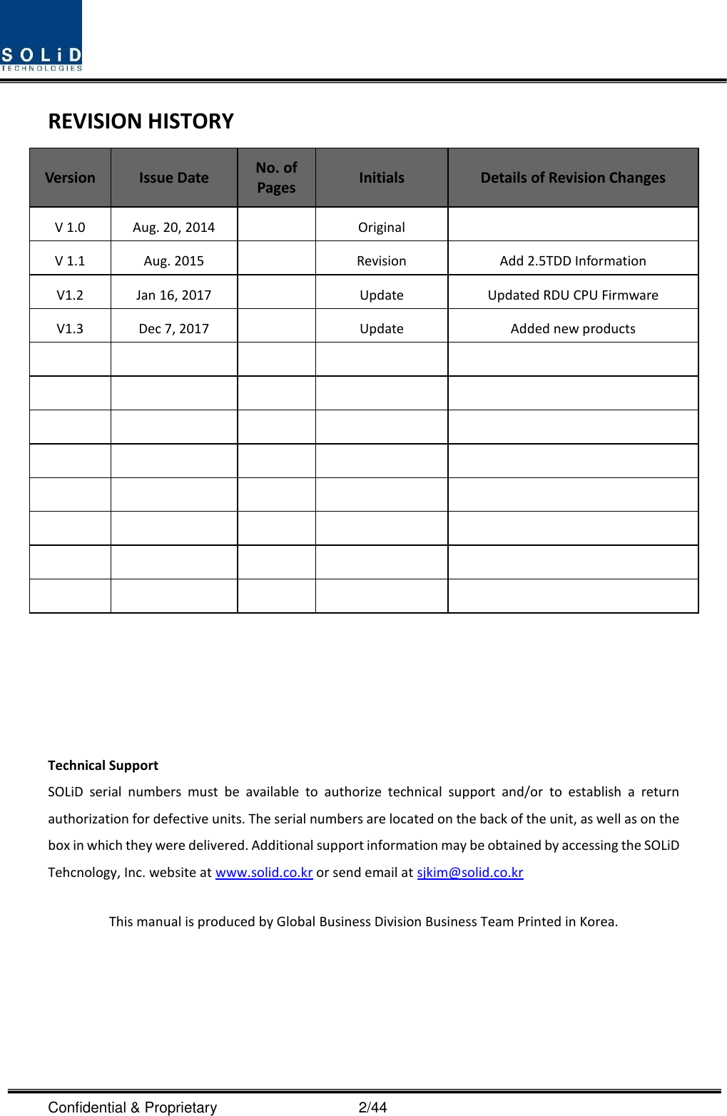
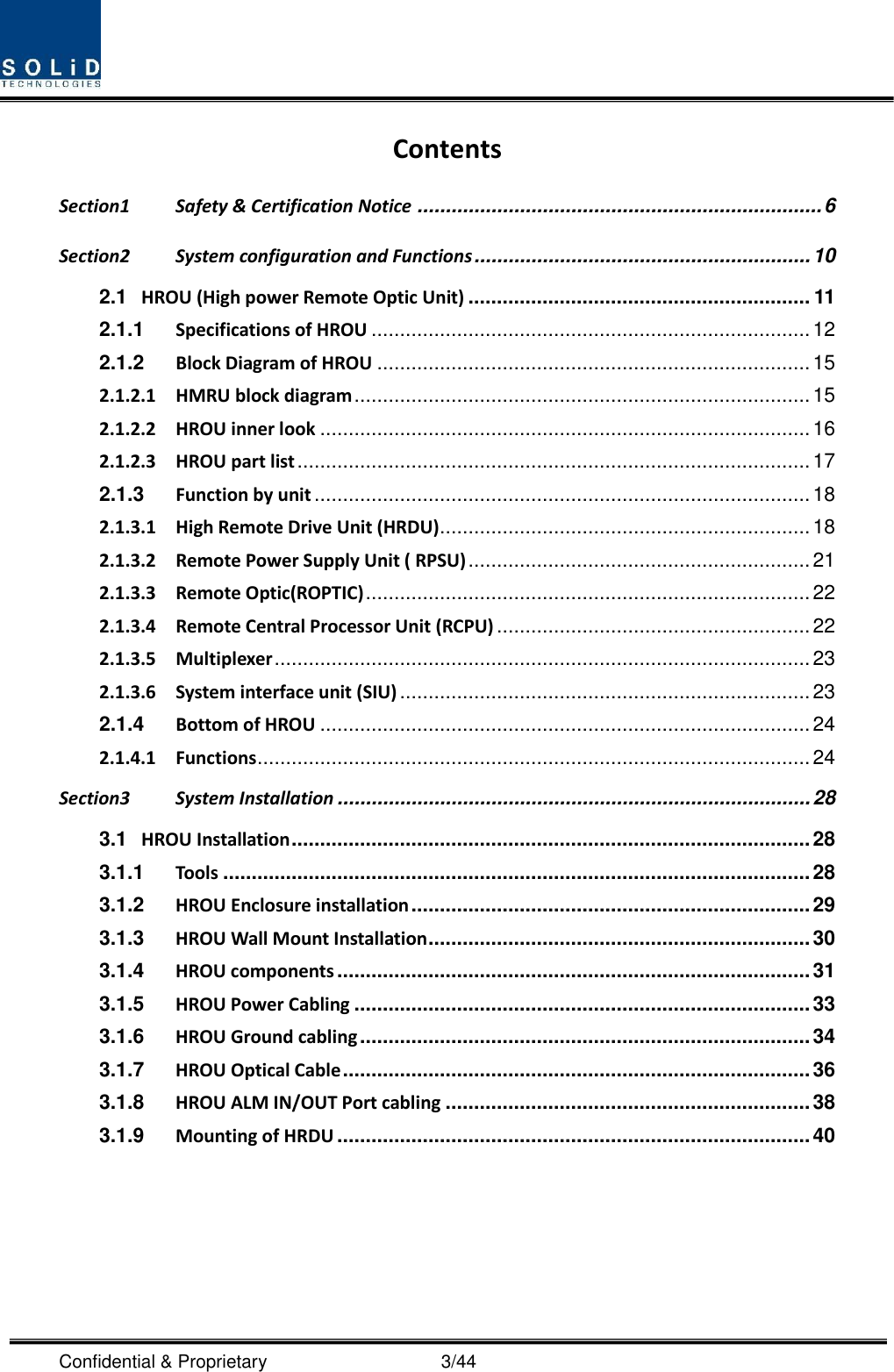
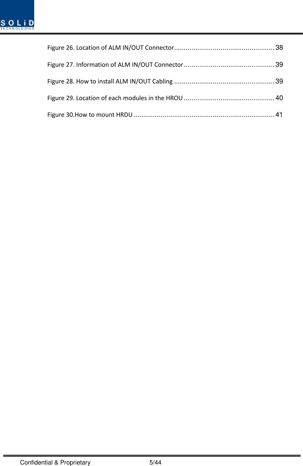
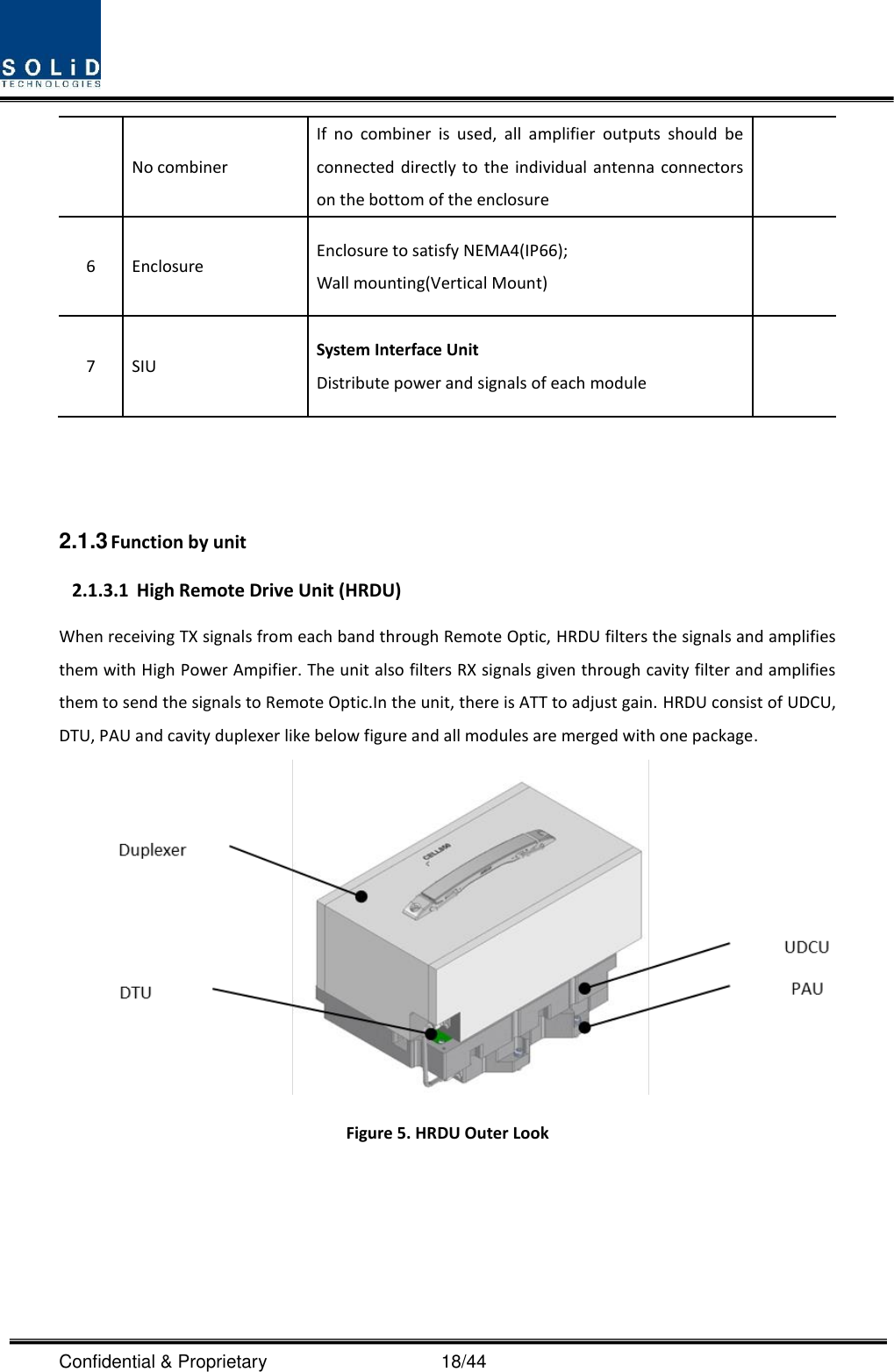
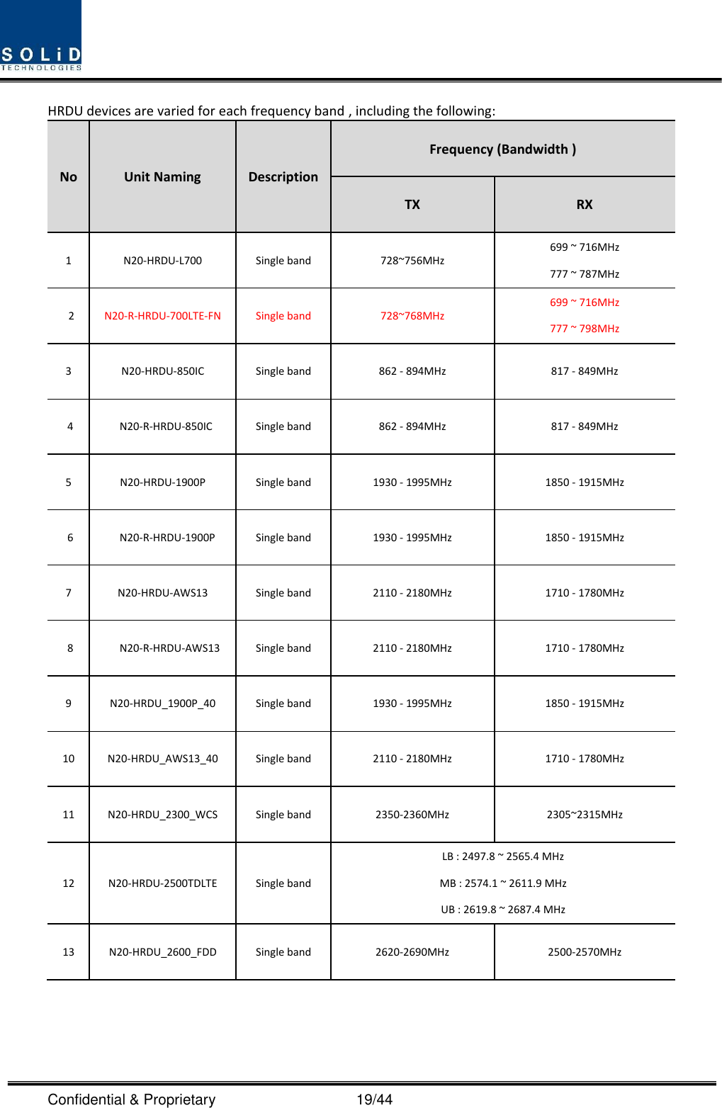
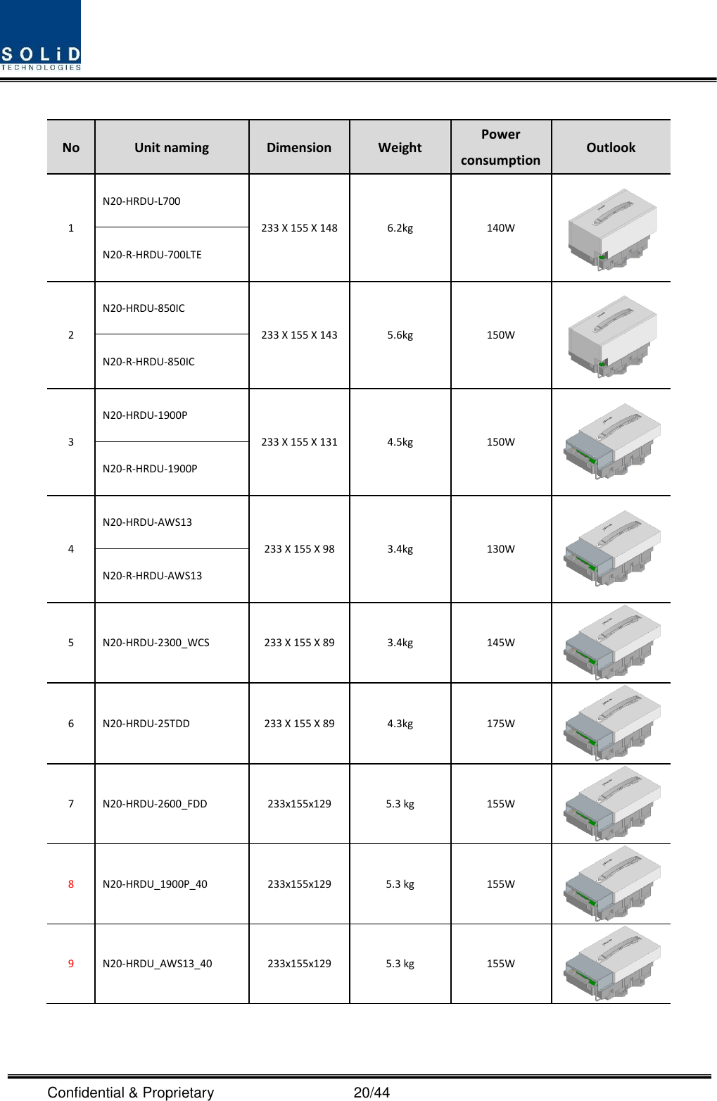
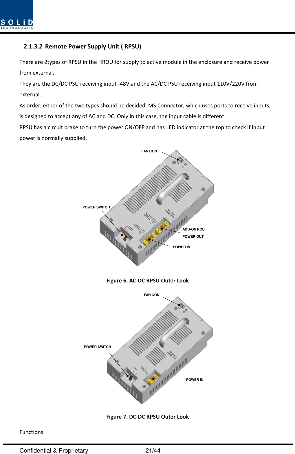
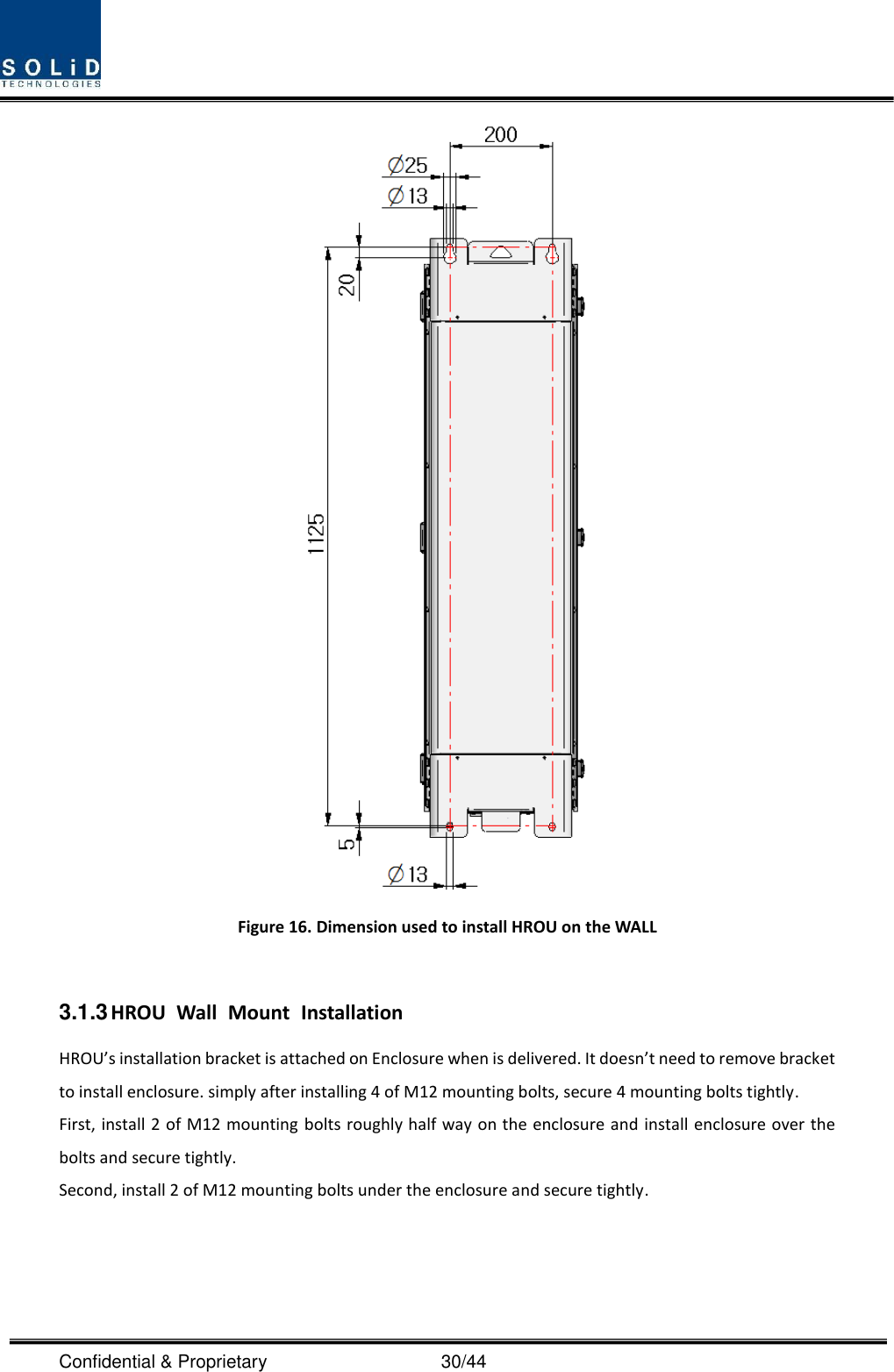
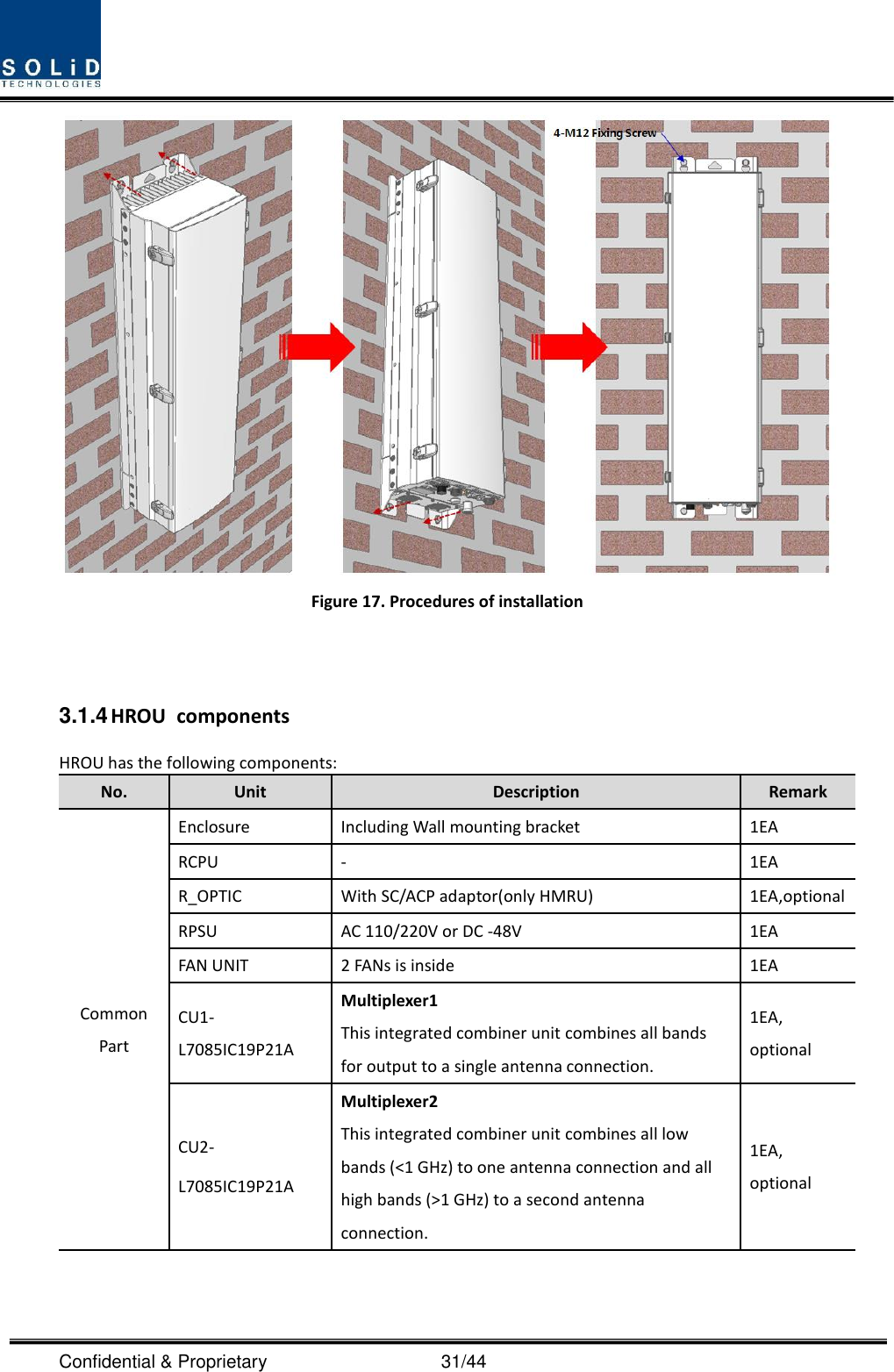
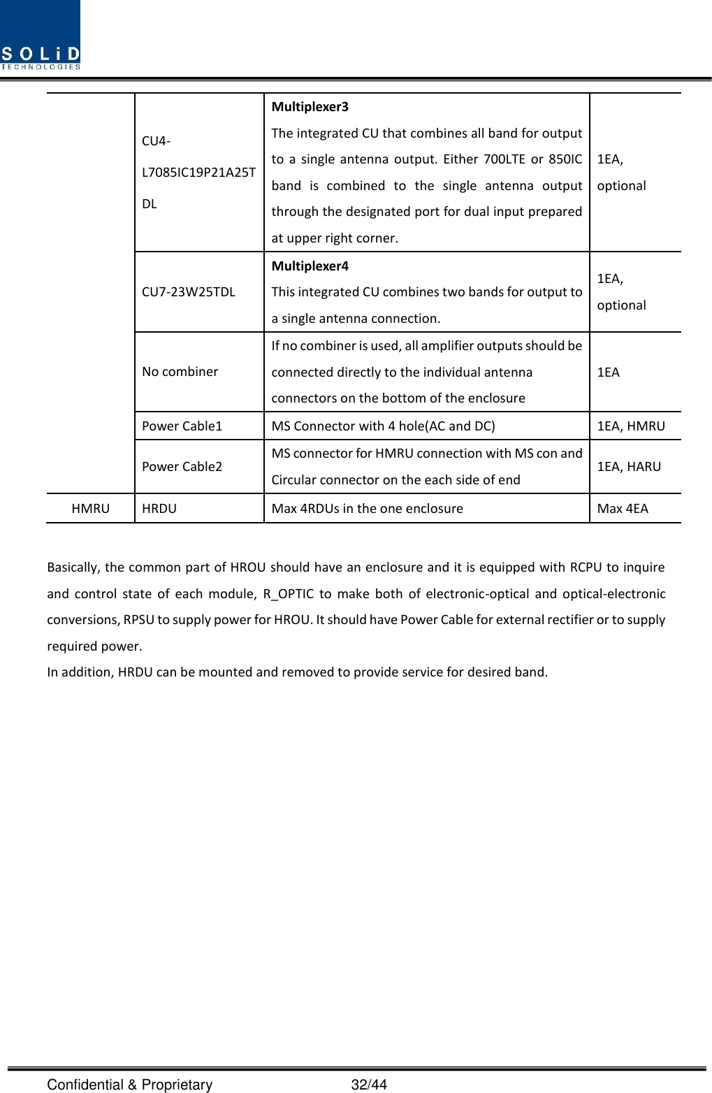
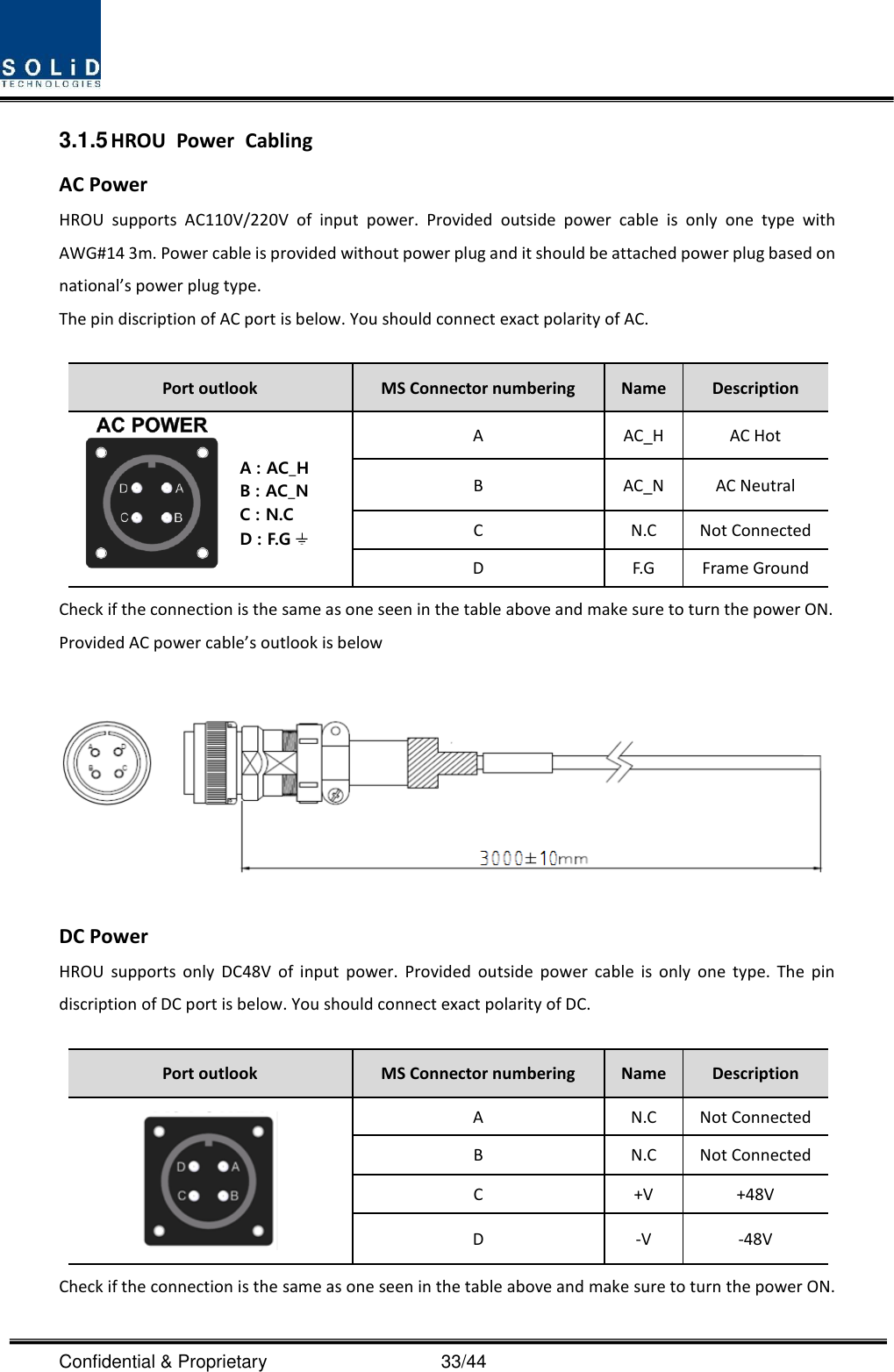
N20-R-HRDU-AWS13 User Manual_180115_rev.2

 Confidential & Proprietary                                      1/44   ALLIANCE_N20 User Manual    Document Reference:     Version:  V1.2 Document Status:  Release 2 Issue Date:  Jan 16, 2017 Author:  Hwan sun Lee Department:  R&D Division Team 3   Authorizing Manager:            Kyung Eun Han
 Confidential & Proprietary                                      2/44 REVISION HISTORY Version Issue Date No. of Pages Initials Details of Revision Changes V 1.0 Aug. 20, 2014  Original  V 1.1 Aug. 2015  Revision Add 2.5TDD Information V1.2 Jan 16, 2017  Update Updated RDU CPU Firmware   V1.3 Dec 7, 2017  Update Added new products                                              Technical Support SOLiD  serial  numbers  must  be  available  to  authorize  technical  support  and/or  to  establish  a  return authorization for defective units. The serial numbers are located on the back of the unit, as well as on the box in which they were delivered. Additional support information may be obtained by accessing the SOLiD Tehcnology, Inc. website at www.solid.co.kr or send email at sjkim@solid.co.kr    This manual is produced by Global Business Division Business Team Printed in Korea.
 Confidential & Proprietary                                      3/44 Contents Section1 Safety & Certification Notice ....................................................................... 6 Section2 System configuration and Functions ........................................................... 10 2.1 HROU (High power Remote Optic Unit) ............................................................ 11 2.1.1 Specifications of HROU ............................................................................. 12 2.1.2 Block Diagram of HROU ............................................................................ 15 2.1.2.1 HMRU block diagram ................................................................................ 15 2.1.2.2 HROU inner look ...................................................................................... 16 2.1.2.3 HROU part list .......................................................................................... 17 2.1.3 Function by unit ....................................................................................... 18 2.1.3.1 High Remote Drive Unit (HRDU) ................................................................. 18 2.1.3.2 Remote Power Supply Unit ( RPSU) ............................................................ 21 2.1.3.3 Remote Optic(ROPTIC) .............................................................................. 22 2.1.3.4 Remote Central Processor Unit (RCPU) ....................................................... 22 2.1.3.5 Multiplexer .............................................................................................. 23 2.1.3.6 System interface unit (SIU) ........................................................................ 23 2.1.4 Bottom of HROU ...................................................................................... 24 2.1.4.1 Functions ................................................................................................. 24 Section3 System Installation ................................................................................... 28 3.1 HROU Installation ........................................................................................... 28 3.1.1 Tools ....................................................................................................... 28 3.1.2 HROU Enclosure installation ...................................................................... 29 3.1.3 HROU Wall Mount Installation ................................................................... 30 3.1.4 HROU components ................................................................................... 31 3.1.5 HROU Power Cabling ................................................................................ 33 3.1.6 HROU Ground cabling ............................................................................... 34 3.1.7 HROU Optical Cable .................................................................................. 36 3.1.8 HROU ALM IN/OUT Port cabling ................................................................ 38 3.1.9 Mounting of HRDU ................................................................................... 40
 Confidential & Proprietary                                      4/44 Contents of Figure Figure 3. HROU consists of 2 unit ...................................................................... 11 Figure 4. HROU outer Look ............................................................................... 12 Figure 5. HMRU Block diagram .......................................................................... 15 Figure 6. Inside of Remote Unit ......................................................................... 16 Figure 7. HRDU Outer Look ............................................................................... 18 Figure 8. AC-DC RPSU Outer Look ...................................................................... 21 Figure 9. DC-DC RPSU Outer Look ...................................................................... 21 Figure 10. R OPTIC Outer Look .......................................................................... 22 Figure 11. AC-DC RPSU Outer Look .................................................................... 23 Figure 12. Multiplexer Outer Look ..................................................................... 23 Figure 13. SIU Outer Look ................................................................................. 24 Figure 14. The Bottom Look of HROU and CU options .......................................... 25 Figure 15. The panel for support CU Option3 with 4 antenna ports ....................... 25 Figure 16. The name of each port on the bottom of HROU ................................... 25 Figure 17. How to install ROU ........................................................................... 29 Figure 18. Dimension used to install HROU on the WALL ...................................... 30 Figure 19. Procedures of installation .................................................................. 31 Figure 20. Location of Ground Terminal.............................................................. 34 Figure 21. Information of Terminal .................................................................... 35 Figure 22. How to install Ground Terminal .......................................................... 35 Figure 23. Location of Optical Connector ............................................................ 36 Figure 24. Information of Optical Connector ....................................................... 37 Figure 25. How to install Optical Cabling ............................................................ 38
 Confidential & Proprietary                                      5/44 Figure 26. Location of ALM IN/OUT Connector .................................................... 38 Figure 27. Information of ALM IN/OUT Connector ............................................... 39 Figure 28. How to install ALM IN/OUT Cabling .................................................... 39 Figure 29. Location of each modules in the HROU ............................................... 40 Figure 30.How to mount HRDU ......................................................................... 41
 Confidential & Proprietary                                      6/44 Section1                                             Safety & Certification Notice
 Confidential & Proprietary                                      7/44 “Only  qualified  personnel  should  handle  the  DAS  equipment.  Any  person  involved  in installation or service of the DAS should understand and follow these safety guidelines.”      -  Obey  all  general  and  regional  installation  and  safety  regulations  relating  to  work  on  high  voltage installations, as well as regulations covering correct use of tools and personal protective equipment.  - The power supply unit in repeaters contains dangerous voltage level, which can cause electric shock. Switch the mains off prior to any work in such a repeater. Any local regulations are to be followed when servicing repeaters.  - When working with units outdoors, make sure to securely fasten the door or cover in an open position to prevent the door from slamming shut in windy conditions.  - Use this unit only for the purpose specified by the manufacturer. Do not carry out any modifications or fit any spare parts which are not sold or recommended by the manufacturer. This could cause fires, electric shock or other injuries.    - Any DAS system or Fiber BDA will generate radio (RF) signals and continuously emit RF energy. Avoid prolonged exposure to the antennas. SOLiD recommends maintaining a  500 cm minimum clearance from the antenna while the system is operating.  - Antennas must be installed in accordance with FCC 27.50 and Part 24, SRSP  502, SRSP 503, SRSP 510 and SRSP 513. With 17dBi gain antennas the height of  the  antenna  above  average  terrain  (HAAT)  must                     not exceed 221.08 m. For different gain antennas refer to the relevant rules and the local licensing auth     orities.      - Do not operate this unit on or close to flammable materials, as the unit may reach high temperatures due to power dissipation.   - Do not use any solvents, chemicals, or cleaning solutions containing alcohol, ammonia, or abrasives on the DAS equipment. Alcohol may be used to clean fiber optic cabling ends and connectors.   - To prevent electrical shock, switch the main power supply off prior to working with the DAS System or Fiber BDA. Never install or use electrical equipment in a wet location or during a lightning storm.   - Do not look into the ends of any optical fiber or directly into the optical transceiver of any digital unit. Use  an  optical  spectrum  analyzer  to  verify  active  fibers.  Place  a  protective  cap  over  any  radiating transceiver or optical fiber connector to avoid the potential of radiation exposure.   - Allow sufficient fiber length to permit routing without severe bends.   - For pluggable equipment, make sure to install the socket outlet near the equipment so that it is easily accessible.   - A readily accessible disconnect device shall be incorporated external to the equipment.
 Confidential & Proprietary                                      8/44 - This power of this system shall be supplied through wiring installed in a normal building.  If powered directly from the mains distribution system, it shall be used additional protection, such as overvoltage protection device  - Only 50 ohm rated antennas, cables and passive equipment shall be used with this remote.    Any equipment attached to this device not meeting this standard may cause degradation and unwanted signals in the bi-directional system.    All components connected to this device must operate in the frequency range of this device.  - Only 50 ohm rated antennas, cables and passive components operating from 150 - 3 GHz shall be used with this device.  - The head end unit must always be connected to the Base Station using a direct cabled connection.    This system has not been approved for use with a wireless connection via server antenna to the base station.  - Access can only be gained by SERVICE PERSONS or by USERS who have been instructed about the reasons for the restrictions applied to the location and about any precautions that shall be taken; and - Access is through the use of a TOOL or lock and key, or other means of security, and is on trolled by the authority responsible for the location. - Notice! Be careful not to touch the Heat-sink part due to high temperature.   - Signal booster warning label message should include        - Certification
 Confidential & Proprietary                                      9/44  FCC: This equipment complies with the applicable sections of Title 47 CFR Parts 15,22,24,27 and 90(Class B) - Use of unauthorized antennas, cables, and/or coupling devices not conforming with ERP/EIRP and/or indoor‐only restrictions is prohibited. - Home/ personal use are prohibited.  UL/CUL: This equipment complies with UL and CUL 1950-1 Standard for safety for information technology equipment,including electrical business equipment   FDA/CDRH:  This  equipment  uses  a  Class  1  LASER  according  to  FDA/CDRH  Rules.This  product conforms to all applicable standards of 21 CFR Chapter 1, Subchaper J, Part 1040 -    IC Booster warning label message should include WARNING: This is NOT a CONSUMER device. It is designed for installation by an installer approved by an ISED licensee. You MUST have an ISED LICENCE or the express consent of an ISED licensee to operate this device.
 Confidential & Proprietary                                      10/44    Section2                           System configuration and Functions
 Confidential & Proprietary                                      11/44    2.1  HROU  (High  power  Remote  Optic  Unit) HROU consists of two  unit, one is HMRU(High power Main Remote Unit) and the other is HARU(High power Add-on Remote Unit). The biggest difference between HMRU and HARU is whether R-OPTIC module exist or not in the enclosure. HMRU receives TX optical signals from ODU and converts them into RF signals. The converted RF signals are amplified through High Power Amp in a corresponding HRDU band combined with UDCU, PAU and Cavity duplexer, and then radiated to the antenna port. When  receiving  RX  signals  through  the  antenna  port,  this  unit  filters  out-of-band  signals  in  a corresponding HRDU and sends the results to R-OPTIC to make electronic-optical conversion of them. After converted, the signals are sent to a upper device of ODU. HMRU can be equipped with up to four HRDUs (High Remote Drive Unit) and the module supports single band only. HARU receives TX RF signal from HMRU and amplifies through High Power Amp in a corresponding HRDU combined with UDCU, PAU and Cavity duplexer, and then radiated to the CU(Combining Unit) When receiving RX signals through the antenna port, HRDU filters out-of band signal in a corresponding HRDU and sends the results to MHRU through RF cable.     Figure 1. HROU consists of 2 unit
 Confidential & Proprietary                                      12/44  Figure 2. HROU outer Look 2.1.1 Specifications of HROU Item Spec. Remark HMRU The rated mean output Power per band 700LTE 850IC 1900P AWS13 2600_FDD +44dBm  R-700LTE-FN R-850IC R-1900P R-AWS13 2300_WCS 2500TDLTE +43dBm 1900P_40   +46dBm AWS13_40 +46dBm
 Confidential & Proprietary                                      13/44 The nominal downlink bandwidth 700LTE 28MHz 728 - 756MHz R-700LTE-FN 40MHz 728 - 768MHz 850IC 32MHz 862 - 894MHz R-850IC 1900P 65MHz 1930 - 1995MHz R-1900P AWS13 70MHz 2110 - 2180MHz   R-AWS13 1900P_40 65MHz 1930 - 1995MHz AWS13_40 70MHz 2110 - 2180MHz   2300_WCS 10MHz 2350 – 2360MHz 2500TDLTE 67.6MHz (LB, UB) 37.8MHz (MB) LB : 2497.8 ~ 2565.4 MHz MB : 2574.1 ~ 2611.9 MHz UB : 2619.8 ~ 2687.4 MHz 2600_FDD 70MHz 2620 - 2690MHz The nominal uplink bandwidth 700LTE 17MHz and 10MHz 699 - 716MHz   777 - 787MHz R-700LTE-FN 17MHz and 20MHz 699 - 716MHz   777 - 798MHz 850IC 32MHz 817 - 849MHz   R-850IC 1900P 65MHz 1850 - 1915MHz   R-1900P AWS13 70MHz 1710 - 1780MHz R-AWS13 1900P_40 65MHz 1850 - 1915MHz   AWS13_40 70MHz 1710 - 1780MHz 2300_WCS 10MHz 2305 – 2315MHz 2500TDLTE 67.6MHz (LB, UB) 37.8MHz (MB) LB : 2497.8 ~ 2565.4 MHz MB : 2574.1 ~ 2611.9 MHz UB : 2619.8 ~ 2687.4 MHz 2600_FDD 70MHz 2500 - 2570 MHz The nominal passband gain Downlink R-700LTE-FN 63dB  700LTE 850IC 59dB
 Confidential & Proprietary                                      14/44 1900P AWS13 2600_FDD 59dB 2300_WCS   2500TDLTE R-850IC R-1900P R-AWS13 65dB 1900P_40W AWS13_40W 62dB Uplink 45dB each band Input/ Output Impedance   50 ohm    Weight 39 Kg Common Part Power consumption 50W Temperature range -25°C to +55°C/ -13 to 131°F Ambient Temperature Humidity Range 0% ~ 90% Non-condensing Sealing (Remote Unit) IEC 60 529 EN 60 529 IP66 Complaint Size(mm) 320 x 1165 x260 Including Bracket 63dB
 Confidential & Proprietary                                      15/44 2.1.2 Block Diagram of HROU 2.1.2.1 HMRU block diagram   Figure 3. HMRU Block diagram
 Confidential & Proprietary                                      16/44 2.1.2.2 ROU inner look  Figure 4. Inside of Remote Unit ** In the HARU enclosure, not need to install R-Optic            HRDU#4HRDU#3HRDU#2HRDU#1R-OPTICRPSUCURCPU
 Confidential & Proprietary                                      17/44 2.1.2.3 HROU part list No. Unit Description Remark 1 HRDU X4 High Remote Drive Unit Consist of UDCU, PAU and cavity filter Filter and high amplify TX signals; Filter and amplify RX signals in low noise amplifier; Remove out-of signals through cavity duplexer Optional Max 4 2 RPSU(AC) Remote Power Supply Unit Input power: 110 VAC/220VAC (85~264V) Output power: +29 VDC  RPSU(DC) Remote Power Supply Unit Input power: -48 VDC(-40.8 ~ -57.6V) Output power: +29 VDC  3 R-OPTIC Remote Optic Make RF conversion of TX optical signals; Convert RX RF signals into optical signals;   Compensates optical loss; 5dBo optical link between ODU(OM4) and ROU; 10dBo optical link between ODU(OM1) and ROU; Fiber Connector: SC/APC Connector; Optical Wavelength: 1310/1550 WDM; Communicates with BIU/OEU though the FSK modem  4 RCPU Remote Central Processor Unit Controls signal of each unit Monitors  BIU/ODU/OEU  status  through  FSK  modem communication  5 CU1-L7085IC19P21A Multiplexer1 This integrated combiner unit combines all bands for output to a single antenna connection.  CU2-L7085IC19P21A Multiplexer2 This integrated combiner unit combines all low bands (<1 GHz) to one antenna connection and all high bands (>1 GHz) to a second antenna connection.
 Confidential & Proprietary                                      18/44 No combiner If  no  combiner  is  used,  all  amplifier  outputs  should  be connected directly to the individual antenna connectors on the bottom of the enclosure 6 Enclosure Enclosure to satisfy NEMA4(IP66);   Wall mounting(Vertical Mount)  7 SIU System Interface Unit Distribute power and signals of each module       2.1.3 Function by unit 2.1.3.1 High Remote Drive Unit (HRDU) When receiving TX signals from each band through Remote Optic, HRDU filters the signals and amplifies them with High Power Ampifier. The unit also filters RX signals given through cavity filter and amplifies them to send the signals to Remote Optic.In the unit, there is ATT to adjust gain. HRDU consist of UDCU, DTU, PAU and cavity duplexer like below figure and all modules are merged with one package.  Figure 5. HRDU Outer Look
 Confidential & Proprietary                                      19/44 HRDU devices are varied for each frequency band , including the following: No Unit Naming Description Frequency (Bandwidth )   TX RX 1 N20-HRDU-L700 Single band 728~756MHz   699 ~ 716MHz   777 ~ 787MHz 2 N20-R-HRDU-700LTE-FN Single band 728~768MHz   699 ~ 716MHz   777 ~ 798MHz 3 N20-HRDU-850IC Single band 862 - 894MHz   817 - 849MHz     4   N20-R-HRDU-850IC Single band 862 - 894MHz   817 - 849MHz   5 N20-HRDU-1900P Single band 1930 - 1995MHz 1850 - 1915MHz     6 N20-R-HRDU-1900P Single band 1930 - 1995MHz 1850 - 1915MHz   7 N20-HRDU-AWS13 Single band 2110 - 2180MHz   1710 - 1780MHz   8 N20-R-HRDU-AWS13 Single band 2110 - 2180MHz   1710 - 1780MHz 9 N20-HRDU_1900P_40 Single band 1930 - 1995MHz 1850 - 1915MHz   10 N20-HRDU_AWS13_40 Single band 2110 - 2180MHz   1710 - 1780MHz 11 N20-HRDU_2300_WCS Single band 2350-2360MHz 2305~2315MHz 12 N20-HRDU-2500TDLTE Single band LB : 2497.8 ~ 2565.4 MHz MB : 2574.1 ~ 2611.9 MHz UB : 2619.8 ~ 2687.4 MHz 13 N20-HRDU_2600_FDD Single band 2620-2690MHz 2500-2570MHz
 Confidential & Proprietary                                      20/44  No Unit naming Dimension Weight Power consumption Outlook 1 N20-HRDU-L700 233 X 155 X 148   6.2kg 140W  N20-R-HRDU-700LTE 2 N20-HRDU-850IC 233 X 155 X 143 5.6kg 150W  N20-R-HRDU-850IC 3 N20-HRDU-1900P 233 X 155 X 131 4.5kg 150W  N20-R-HRDU-1900P 4 N20-HRDU-AWS13 233 X 155 X 98 3.4kg 130W  N20-R-HRDU-AWS13 5 N20-HRDU-2300_WCS 233 X 155 X 89 3.4kg 145W  6 N20-HRDU-25TDD 233 X 155 X 89 4.3kg 175W  7 N20-HRDU-2600_FDD 233x155x129 5.3 kg 155W  8 N20-HRDU_1900P_40 233x155x129 5.3 kg 155W  9 N20-HRDU_AWS13_40 233x155x129 5.3 kg 155W
 Confidential & Proprietary                                      21/44 2.1.3.2 Remote Power Supply Unit ( RPSU) There are 2types of RPSU in the HROU for supply to active module in the enclosure and receive power from external.   They are the DC/DC PSU receiving input -48V and the AC/DC PSU receiving input 110V/220V from external. As order, either of the two types should be decided. MS Connector, which uses ports to receive inputs, is designed to accept any of AC and DC. Only in this case, the input cable is different. RPSU has a circuit brake to turn the power ON/OFF and has LED indicator at the top to check if input power is normally supplied.  Figure 6. AC-DC RPSU Outer Look  Figure 7. DC-DC RPSU Outer Look Functions: POWER SWITCHFAN CONPOWER INADD-ON ROU POWER OUTPOWER INPOWER SWITCHFAN CON
 Confidential & Proprietary                                      22/44  Providing a circuit breaker to turn AC power ON/OFF  Providing DC power each HRDU    Providing DC power and signal to FAN tray  LED indicators for showing alarm staus of PSU     Caution DOUBLE POLE/NEUTRAL FUSING    2.1.3.3 Remote Optic(ROPTIC) Remote Optic converts optical signals into RF signals and performs vice versa. It also has internal ATT for optical  compensation  to  compensate  for  optical  cable  loss.  It  provides  two  path  in  pairs(TX/RX)  to transport RF signal to ARUs.  Figure 8. R OPTIC Outer Look      2.1.3.4 Remote Central Processor Unit (RCPU) RCPU  can  monitor  and  control  each  module  of  HROU.  This  unit  receives  and  analyzes  upper communication data from Remote Optic and reports the unit's own value to upper devices. At the front of the module, it has LED indicator to show system status, letting you check any abnormalities at a time. At the same front, it also has communication LED Indicators to show communication status with upper
 Confidential & Proprietary                                      23/44 devices. Through Local port, the unit enables you to check and control device status through PC and laptop.   It provides three interface port with ARUs to communicate with these. It also provide dry contact port, which is (1) output port and (1) input port.     Figure 9. AC-DC RPSU Outer Look  2.1.3.5 Multiplexer Multiplexer it called combine unit(CU) works as a module to combine or distribute multiple signals into one or two antennas. This device has a port to combine multiple signals. You need to connect input and output ports of RDU through a corresponding port.       Figure 10. Multiplexer Outer Look  2.1.3.6 System interface unit (SIU) This unit connect with HRDU, R CPU, R Optic and RPSU. SIU distributes power and signals to each module. Each unit need to connected to the correct slot of the SIU.
 Confidential & Proprietary                                      24/44   Figure 11. SIU Outer Look  2.1.4 Bottom of HROU 2.1.4.1 Functions The Bottom look of HROU depends on the combine unit(CU) with 3 options. The CU option1 and 2 need to install a specified CU in the enclosure like the table below explains. Thus, the CU option1 has one antenna port, the CU option2 has two antenna ports. Finally, the CU option3 with 4 antenna ports is not necessary to install CU in the enclosure and needs to apply the panel with 4-DIN Type on the bottom of HROU.   See table and drawing below for.
 Confidential & Proprietary                                      25/44  Figure 12. The Bottom Look of HROU and CU options  Figure 13. The panel for support CU Option3 with 4 antenna ports  Figure 14. The name of each port on the bottom of HROU  Power InPower Out(Only AC)T/RX RF port to ARU  I/OExternalALM In/OutExternalFAN UnitGND LUG Optic PortThe Panel  for CU Option 1 and 2
 Confidential & Proprietary                                      26/44 No Port HMRU Remark 1 Optical Port 1EA SC/APC, Waterproof Optiacl Input port 2   T/RX RF Port   2EA N Type-Female Connected for transmittering TX to ARU   and recieving RX signal from ARU. 3 ANT1 1EA DIN-type female_CU option1 ,2 and 3 4 ANT2 1EA DIN-type female_CU option2 and 3 5 ANT3 1EA DIN-type female_Only CU Option3 6 ANT4 1EA DIN-type female_Only CU Option3 7 Power IN   1EA MS-Con, Waterproof AC Power IN Or DC Power IN 8 Power OUT 1EA MS-Con, Waterproof AC 120V Output port(Only AC) to ARU 9 External FAN unit 1EA Waterproof-Con 10 GND LUG PORT 1EA Terminal for system ground 11 External ALM In/Out 1EA Input/output terminal for dry contact 12 I/O Port 1EA Port for communicate with ARU  POWER PORT Power ports are used for power-supplying of -48V DC or 120V AC, and specific power cable should be applied to each different types of ROU power supply (AC/DC or DC/DC). Below figure is naming of the power supply by type.  AC Power Port outlook MS Connector numbering Name Description A AC_H AC Hot B AC_N AC Neutral C N.C Not Connected
 Confidential & Proprietary                                      27/44  D F.G Frame Ground  DC Power Port outlook MS Connector numbering Name Description  A N.C Not Connected B N.C Not Connected C +V +48V D -V -48V  I/O PORT I/O ports are reserved ports for ARU for future implementation, and used to monitor the status and control the equipments. Below figure is naming of the I/O ports.
 Confidential & Proprietary                                      28/44    Section3                                           System Installation     3.1  HROU  Installation This chapter describes how to install each unit and optical cables, along with power cabling method. In detail, the chapter describes how to install shelves or enclosuers of each unit, Power Cabling method and  Optic  Cabling  and  RF  Interface.  Furthermore,  by  showing  power  consumption  of  modules  to  be installed in each unit, it presents Power Cabling budget in a simple way. Then, it describes the quantity of components of modules to be installed in each unit and expansion method.   3.1.1 Tools Tools needed for installation is table below No Tools Q’ty Specification Remark 1  1 +, 3Ø  Length is more than 20mm For fixing HRDU 2  1 33mm To tighten antenna port 3  1 19mm To CU N-type port
 Confidential & Proprietary                                      29/44 3.1.2 HROU  Enclosure  installation HROU is designed to be water- and dirt-proof. The unit has the structure of one-Body enclosure. It satisfies water-proof and quake-proof standards equivalent of NEMA4(IP65). The way to install for both HMRU and  ARU  has  same  method.  Basically  HROU  is  attached  with  wall  mountable  bracket.  HROU  can  be mounted into either of wall or on a pole.    Figure 15. How to install ROU
 Confidential & Proprietary                                      30/44  Figure 16. Dimension used to install HROU on the WALL    3.1.3 HROU  Wall  Mount  Installation HROU’s installation bracket is attached on Enclosure when is delivered. It doesn’t need to remove bracket to install enclosure. simply after installing 4 of M12 mounting bolts, secure 4 mounting bolts tightly. First, install 2 of M12 mounting bolts roughly half way on the enclosure and install enclosure over the bolts and secure tightly. Second, install 2 of M12 mounting bolts under the enclosure and secure tightly.
 Confidential & Proprietary                                      31/44  Figure 17. Procedures of installation   3.1.4 HROU  components HROU has the following components: No. Unit Description Remark Common Part Enclosure Including Wall mounting bracket 1EA RCPU - 1EA R_OPTIC With SC/ACP adaptor(only HMRU) 1EA,optional RPSU AC 110/220V or DC -48V 1EA FAN UNIT 2 FANs is inside 1EA CU1-L7085IC19P21A Multiplexer1 This integrated combiner unit combines all bands for output to a single antenna connection. 1EA, optional CU2-L7085IC19P21A Multiplexer2 This integrated combiner unit combines all low bands (<1 GHz) to one antenna connection and all high bands (>1 GHz) to a second antenna connection. 1EA, optional
 Confidential & Proprietary                                      32/44 CU4- L7085IC19P21A25TDL Multiplexer3 The integrated CU that combines all band for output to a  single antenna output.  Either  700LTE or  850IC band  is  combined  to  the  single  antenna  output through the designated port for dual input prepared at upper right corner. 1EA, optional CU7-23W25TDL Multiplexer4 This integrated CU combines two bands for output to a single antenna connection. 1EA, optional No combiner If no combiner is used, all amplifier outputs should be connected directly to the individual antenna connectors on the bottom of the enclosure 1EA Power Cable1 MS Connector with 4 hole(AC and DC) 1EA, HMRU Power Cable2 MS connector for HMRU connection with MS con and Circular connector on the each side of end 1EA, HARU HMRU HRDU Max 4RDUs in the one enclosure Max 4EA  Basically, the common part of HROU should have an enclosure and it is equipped with RCPU to inquire and  control state  of  each  module,  R_OPTIC  to  make  both  of  electronic-optical  and  optical-electronic conversions, RPSU to supply power for HROU. It should have Power Cable for external rectifier or to supply required power. In addition, HRDU can be mounted and removed to provide service for desired band.
 Confidential & Proprietary                                      33/44 3.1.5 HROU  Power  Cabling AC Power HROU  supports  AC110V/220V  of  input  power.  Provided  outside  power  cable  is  only  one  type  with AWG#14 3m. Power cable is provided without power plug and it should be attached power plug based on national’s power plug type. The pin discription of AC port is below. You should connect exact polarity of AC.  Port outlook MS Connector numbering Name Description  A AC_H AC Hot B AC_N AC Neutral C N.C Not Connected D F.G Frame Ground Check if the connection is the same as one seen in the table above and make sure to turn the power ON. Provided AC power cable’s outlook is below   DC Power HROU  supports only DC48V  of  input  power.  Provided  outside power  cable  is  only  one type. The pin discription of DC port is below. You should connect exact polarity of DC.  Port outlook MS Connector numbering Name Description  A N.C Not Connected B N.C Not Connected C +V +48V D -V -48V Check if the connection is the same as one seen in the table above and make sure to turn the power ON. A : AC_HB : AC_NC : N.CD : F.G
 Confidential & Proprietary                                      34/44 Provided DC power cable’s outlook is below    3.1.6 HROU  Ground  cabling The Grounding terminal is located at the bottom of HROU enclosure fixed by M6 screw. Compression terminal is attached already when is delivered. The recommended thickness of cable is AWG#6 copper grounding wire.  Figure 18. Location of Ground Terminal
 Confidential & Proprietary                                      35/44 The specification of compression terminal is like below.  Figure 19. Information of Terminal The required part number is JOCT 16-6 supporting AWG 6. The way to install the grounding cable comply with below procedures.     Figure 20. How to install Ground Terminal
 Confidential & Proprietary                                      36/44 The procedures are   1. Loosen a two M6 screws and then take compression terminal off   2. Insert AWG#6 Grounding Wire into terminal and then compress a terminal using tool 3. Assemble the terminal which made in step “2” using 2xM6 screws 4. Cut the ground wire to proper length and connect it to the earth ground source ( Round terminals located on the side of a 1 mm2 (16 AWG) or more wires Using permanently connected to earth.)  3.1.7 HROU Optical Cable The Optical  Connector  is located  at the bottom of Remote  Unit  enclosure  fixed. Optical  Cable can be connected by using connectors.  Figure 21. Location of Optical Connector  The specification of compression Optic Connector is like below.
 Confidential & Proprietary                                      37/44  Figure 22. Information of Optical Connector  The way to install the Optical cable comply with below procedures The procedures are
 Confidential & Proprietary                                      38/44  Figure 23. How to install Optical Cabling  3.1.8 HROU ALM IN/OUT Port cabling The ALM IN/OUT Connector is located at the bottom of Remote Unit enclosure fixed. Cable can be connected by using connectors.  Figure 24. Location of ALM IN/OUT Connector  The specification of compression ALM IN/OUT Connector is like below
 Confidential & Proprietary                                      39/44  Figure 25. Information of ALM IN/OUT Connector  The way to install the ALM IN/OUT Connector comply with below procedures    Figure 26. How to install ALM IN/OUT Cabling  The procedures are Peel off sheath of the cable. Assemble all components on cable as following.
 Confidential & Proprietary                                      40/44 Connect all wires to insert according to wire list, then tighten all small screws. The torque for small screws is 0.2Nm. Assemble plastic nut to main body. Recommended torque : 1.0Nm. (Note : The key inside the main body must go straight to slot of insert.) Push the cable seal, pinch ring into the main body, then tighten the pressure screw into the body with recommended torque : 1.0Nm.  3.1.9 Mounting  of  HRDU HROU has slots to enable up to four HRDU modules to be mounted in it. You  can  mount  a  HRDU  into  designated  slot  surely  and  should  install  each  HRDU  into  its designated location as shown in the installation diagram on the door of enclosure.   It is not possible to provide services with a HRDU module alone; you need to connect HRDU cavity duplexer antenna port with CU’s designated port.    Figure 27. Location of each modules in the HROU
 Confidential & Proprietary                                      41/44 The Remote Unit holds a maximum of 4 HRDUs. Guide brackets on the bottom of each HRDU slot simplify installation as described below. MRDU installation requires a +No.1 tip size screwdriver.        Figure 28.How to mount HRDU
 Confidential & Proprietary                                      42/44 The procedures are   1. Lift the HRDU onto the guide bracket and ensure the MRDU is level left to right 2. Push the HRDU into the corresponding slot in the direction of the heat sink while levelling the MRDU to guide bracket 3. Make sure the HRDU is firmly inserted into the corresponding slot. Tighten the 4 corner screws to secure the unit 4. Install HRDU blank cards in all unused slots in the remote. First insert the blank card into the corresponding slot, then tighten the captive screw to secure it   "The Manufacturer's rated output power of this equipment is for single carrier operation. For situations when multiple carrier signals are present, the rating would have to be reduced by 3.5 dB, especially where the output signal is re-radiated and can cause interference to adjacent band users. This power reduction is to be by means of input power or gain reduction and not by an attenuator at the output of the device."
 Confidential & Proprietary                                      43/44   RSS-GEN, Sec. 7.1.2 – (transmitters)  Under Industry Canada regulations, this radio transmitter may only operate using an antenna of a type and maximum (or lesser) gain approved for the transmitter by Industry Canada. To reduce potential radio interference to other users, the antenna type and its gain should be so chosen that the equivalent isotropically radiated power (e.i.r.p.) is not more than that necessary for successful communication.  Conformément à la réglementation d’Industrie Canada, le présent émetteur radio peut fonctionneravec une antenne d’un type et d’un gain maximal (ou inférieur) approuvé pour l’émetteur par Industrie Canada. Dans le but de réduire les risques de brouillage radioélectrique à l’intention desautres utilisateurs, il faut choisir le type d’antenne et son gain de sorte que la puissance isotroperayonnée quivalente (p.i.r.e.) ne dépassepas l’intensité nécessaire à l’établissement d’une communication satisfaisante.     RSS-GEN, Sec. 7.1.2 – (detachable antennas)  This radio transmitter (identify the device by certification number, or model number if Category II)has been approved by Industry Canada to operate with the antenna types listed below with the maximum permissible gain and required antenna impedance for each antenna type indicated. Antenna types not included in this list, having a gain greater than the maximum gain indicated for that type, are strictly prohibited for use with this device.  Le présent émetteur radio (identifier le dispositif par son numéro de certification ou son numéro de modèle s’il fait partie du matériel de catégorie I) a été approuvé par Industrie Canada pour fonctionner avec les types d’antenne énumérés ci-dessous et ayant un gain admissible maximal et l’impédance requise pour chaque type d’antenne. Les types d’antenne non inclus dans cette liste,ou dont le gain est supérieur au gain maximal indiqué, sont strictement interdits pour l’exploitation de l’émetteur.  RF Radiation Exposure
 Confidential & Proprietary                                      44/44 This equipment complies with RF radiation exposure limits set forth for an uncontrolled environment. This equipment should be installed and operated with a minimum distance of 500 cm between the radiator and your body. This transmitter must not be co-located or operating in conjunction with any other antenna or transmitter. RF exposure will be addressed at time of installation and the use of higher gain antennas may require larger separation distances.  RSS-102 RF Exposure L’antenne (ou les antennes) doit être installée de façon à maintenir à tout instant une distance minimum de au moins 500 cm entre la source de radiation (l’antenne) et toute personne physique. Cet appareil ne doit pas être installé ou utilisé en conjonction avec une autre antenne ou émetteur.  -    IC Booster warning label message should include WARNING: This is NOT a CONSUMER device. It is designed for installation by an installer approved by an ISED licensee. You MUST have an ISED LICENCE or the express consent of an ISED licensee to operate this device.

Navigation menu