SORIN CRM CRTDSOR1841 Implantable cardioverter defibrillator with RF wireless communication availability User Manual
SORIN CRM Implantable cardioverter defibrillator with RF wireless communication availability
UserManual.wiki
>
SORIN CRM
>
CRTDSOR1841 User Manual
User manual
Navigation menu
Upload a User Manual
Namespaces
Wiki Guide
HTML
PDF
Info
Views
User Manual
Discussion / Help
Navigation
![4. WARNINGS AND PRECAUTIONS4.1. RISKS RELATED TO MEDICAL ENVIRONMENTIt is advisable to carefully monitor defibrillator operation prior to and after any medical treatment during which an electrical current from an external source passes through the patient's body.Magnetic Resonance Imaging:MRI is strictly contraindicated in cardiac defibrillator patients.Radiofrequency ablation:A radiofrequency ablation procedure in a patient with a generator may cause device malfunction or damage. RF ablation risks may be minimized by:1. Programming Shock Therapy and ATP to OFF.2. Avoiding direct contact between the ablation catheter and the implanted lead or generator.3. Positioning the ground, placing it so that the current pathway does not pass through or near the device, i.e. place the ground plate under the patient’s buttocks or legs.4. Having external defibrillation equipment available.Electrocautery or diathermy device:Diathermy and electrocautery equipment should not be used. If such devices must be used:1. Keep the current path and ground plate as far away from the device and the leads as possible (a minimum of 15 cm [six inches]). 2. Before procedure, deactivate ATP and shock therapies.3. During the procedure, keep the electrocautery device as far as possible from the cardiac defibrillator. Set it at minimum intensity. Use it briefly.4. After the procedure, check for proper implant function. The device should never be exposed directly to the diathermy source.External defibrillation:PLATINIUM SonR CRT-D is protected from external defibrillation shocks.1. Before external defibrillation, deactivate ATP and shock therapies.2. During external defibrillation, it is advisable to avoid placing the defibrillating paddles directly over the casing or over the leads. The defibrillating paddles should preferably be placed in an anteroposterior position.3. Avoid any direct contact between the defibrillation paddles and the conductive parts of the implanted leads or casing of the implanted device.4. After external defibrillation, check for proper device function.Radiation therapy:Avoid exposure to ionizing radiation. Betatrons are contraindicated. If high doses of radiation therapy cannot be avoided, the defibrillator should be protected from direct exposure with a protection shield. ATP and shock therapies should be disabled during exposure and proper device function should be checked regularly afterwards. Resulting damage may not be immediately detectable. If irradiation of tissues close to the implantation site is necessary, it is recommended that the cardiac defibrillator be moved. As a safety measure, an external defibrillator should be immediately available.Lithotripsy:Lithotripsy may permanently damage the device if it is at the focal point of the lithotripsy beam. If lithotripsy must be used, keep the defibrillator at least 2.5 to 5 cm (1-2 inches) away from the focal point of the lithotripsy beam.SORIN – PLATINIUM SonR CRT-D – U463A 9](https://usermanual.wiki/SORIN-CRM/CRTDSOR1841/User-Guide-2621344-Page-11.png)
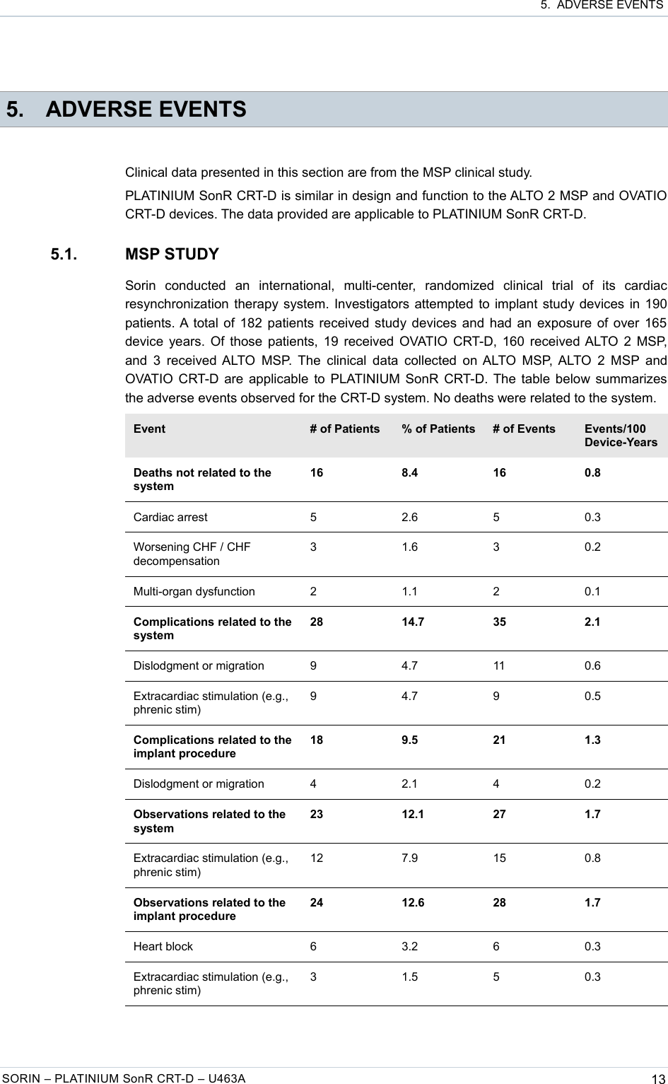
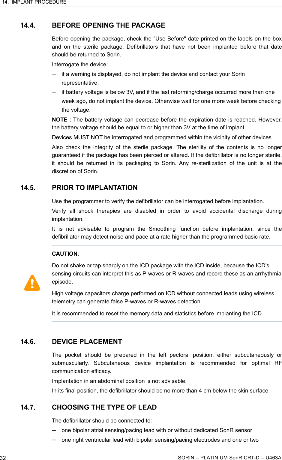
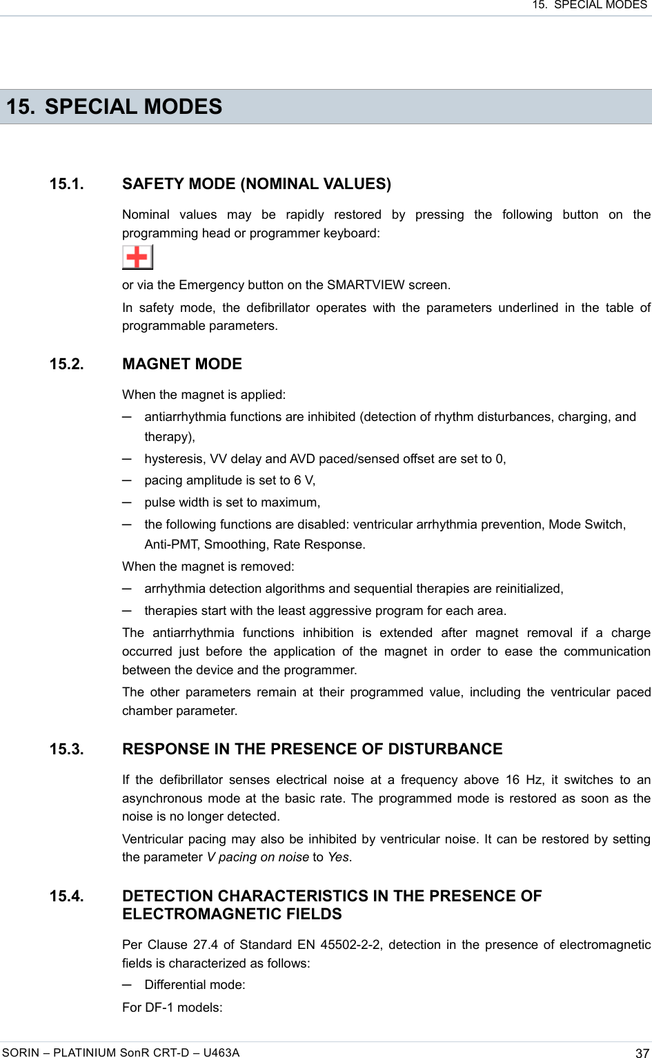
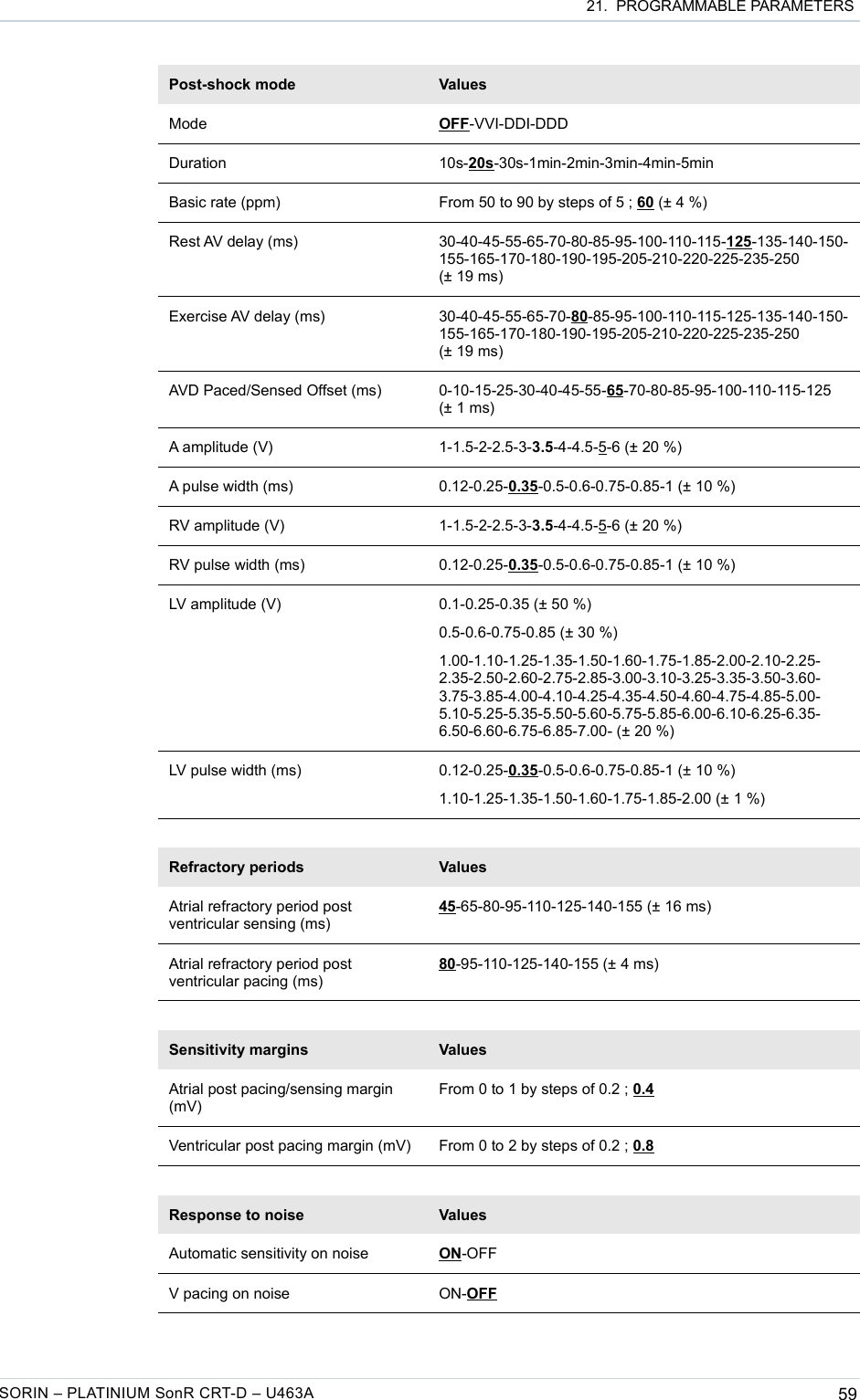
![21. PROGRAMMABLE PARAMETERS─System integrityLead Alerts ValuesAbnormal A lead impedance ON-OFFAbnormal A lead low limit (Ohm) 200-250-300-350-400-450-500Abnormal A lead high limit (Ohm) 1500-1750-2000-2500-3000Abnormal RV lead impedance ON-OFFAbnormal RV lead low limit (Ohm) 200-250-300-350-400-450-500Abnormal RV lead high limit (Ohm) 1500-1750-2000-2500-3000Abnormal LV lead impedance ON-OFFAbnormal LV lead low limit (Ohm) 200-250-300-350-400-450-500Abnormal LV lead high limit (Ohm) 1500-1750-2000-2500-3000Abnormal RV coil impedance ON-OFFAbnormal SVC coil impedance ON-OFFAbnormal Shock impedance (1) ON-OFF(1) Normal impedance range [20 Ohm-200 Ohm]Clinical status ValuesV oversensing ON-OFFHigh AT/AF burden ON-OFFAT/AF limit (on 24h) (h) 0.5-1-3-6-12-24Fast V Rate during AT/AF ON-OFFFast V Rate limit (ppm) 80-90-100-110-120Fast V Duration limit (h) 0.5-1-3-6-12-24Limited % of V pacing in CRT ON-OFFLimited % of V pacing (%) 50-70-80-85-90-95Therapy information ValuesShock disabled ON-OFFShocks delivered OFF-All shocks-Inefficient shock-Inefficient max shockATP delivered ON-OFFSORIN – PLATINIUM SonR CRT-D – U463A 65](https://usermanual.wiki/SORIN-CRM/CRTDSOR1841/User-Guide-2621344-Page-67.png)