SORIN CRM CRTDSOR1844 Implantable Cardioverter defibrillator with RF wireless communication availability User Manual Sorin CRM
SORIN CRM Implantable Cardioverter defibrillator with RF wireless communication availability Sorin CRM
User Manual.pdf
PLATINIUM 4LV SonR CRT-D 1844
IMPLANT MANUAL
Implantable cardioverter debrillator with cardiac
resynchronization therapy SonR 4LV CRT-D models
– –
blank
2
10 kOhm
L V , IS4-LLLL
RV, DF4 - LLHH RV, DF4 - LLHH
RA, IS-1 BI / SonR
RA, IS-1 BI / SonR
RA,SO NR
L V , IS4-LLLL
R V ,
DF4 -LLHH
SORIN PLATINIUM 4LV SonR CRT-D
2.66 V
> 3.2 V
Leads connection - 1844 model
2.66 V
> 3.2 V
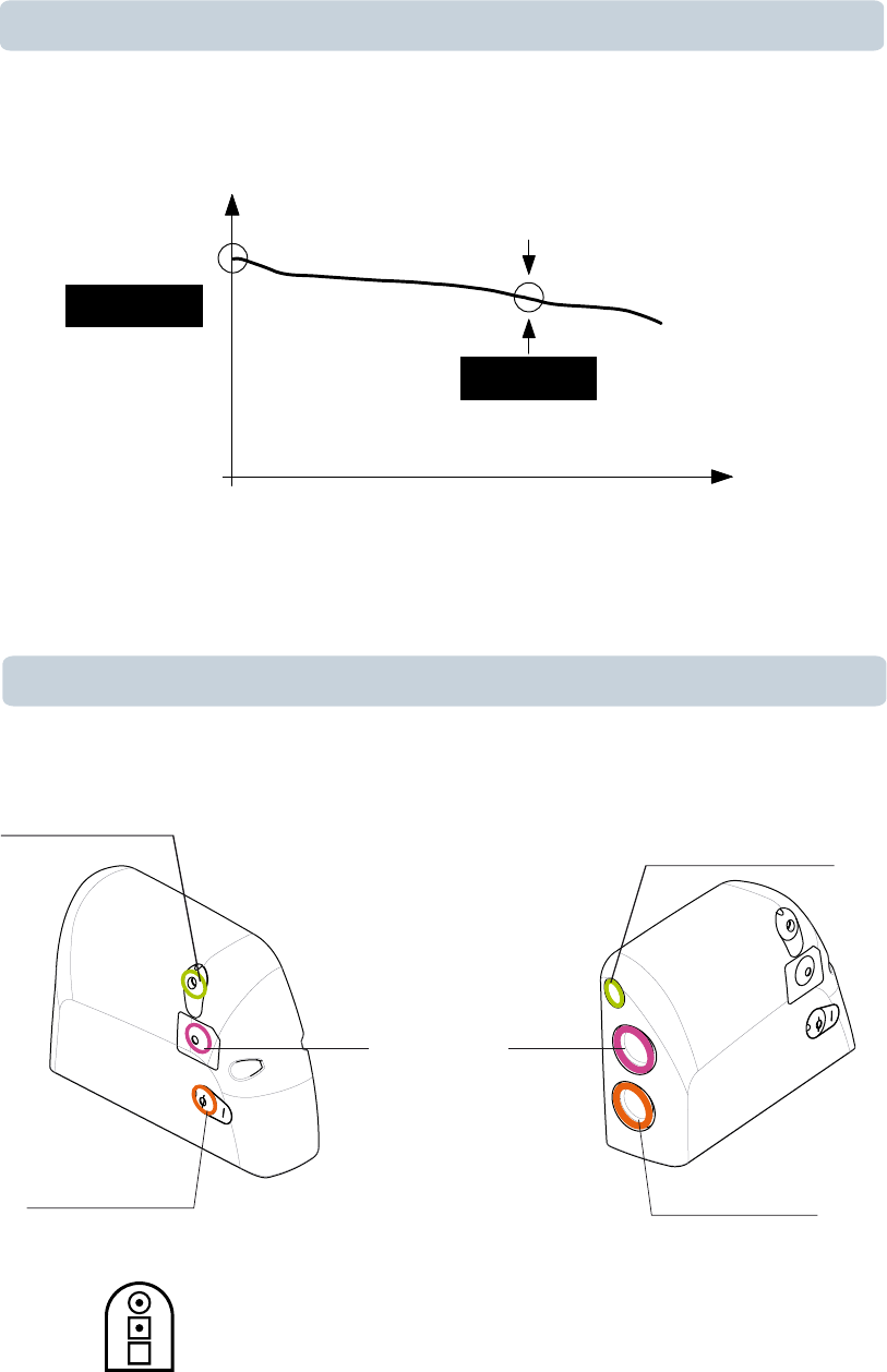
Battery depletion
Reminder
2.62 V
> 3.2 V
voltage
years
RRT
BOS
SORIN – PLATINIUM 4LV SonR CRT-D 1844 – U906A
blank
4

TABLE OF CONTENTS
1. GENERAL DESCRIPTION ........................................................................................ 8
2. INDICATIONS ............................................................................................................ 9
3. CONTRAINDICATIONS........................................................................................... 10
4. WARNINGS AND PRECAUTIONS.......................................................................... 11
Risks related to medical environment ...................................................................... 12
Sterilization, storage and handling ........................................................................... 13
Implantation and device programming ..................................................................... 13
Lead evaluation and lead connection....................................................................... 14
Generator explant and disposal ............................................................................... 15
5. ADVERSE EVENTS................................................................................................. 16
MSP study ................................................................................................................ 16
Potential adverse events .......................................................................................... 17
6. CLINICAL STUDIES ................................................................................................ 18
MSP clinical study .................................................................................................... 18
7. PATIENT SELECTION AND TREATMENT ............................................................. 22
Individualization of treatment.................................................................................... 22
Specific patient populations...................................................................................... 22
8. PATIENT COUNSELLING INFORMATION ............................................................. 24
9. DECLARATION OF CONFORMITY ........................................................................ 25
10. PHYSICIAN GUIDELINES....................................................................................... 27
Physician training ..................................................................................................... 27
Directions for use ..................................................................................................... 27
Maintaining device quality ........................................................................................ 27
V-V Programming Recommendation........................................................................ 28
11. PATIENT INFORMATION ........................................................................................ 29
12. HOW SUPPLIED...................................................................................................... 30
Sterility...................................................................................................................... 30
Warranty and replacement policy............................................................................. 30
13. DEVICE DESCRIPTION .......................................................................................... 31
14. IMPLANT PROCEDURE ......................................................................................... 33
Necessary equipment............................................................................................... 33
Packaging................................................................................................................. 33
Optional equipment .................................................................................................. 33
Before opening the package .................................................................................... 34
Prior to implantation ................................................................................................. 34
Device placement..................................................................................................... 34
4.1.
4.2.
4.3.
4.4.
4.5.
5.1.
5.2.
6.1.
7.1.
7.2.
10.1.
10.2.
10.3.
10.4.
12.1.
12.2.
14.1.
14.2.
14.3.
14.4.
14.5.
14.6.
SORIN – PLATINIUM 4LV SonR CRT-D 1844 – U906A 5

Choosing the type of lead......................................................................................... 34
Shock configuration (+ -> -)...................................................................................... 35
Measurement of thresholds at implant ..................................................................... 36
Leads connection ..................................................................................................... 36
Device implantation .................................................................................................. 38
Tests and programming............................................................................................ 38
15. SPECIAL MODES.................................................................................................... 39
Safety mode (nominal values).................................................................................. 39
Magnet mode ........................................................................................................... 39
Response in the presence of disturbance ................................................................ 39
Detection characteristics in the presence of electromagnetic fields......................... 39
Protection against short-circuits ............................................................................... 40
16. MAIN FUNCTIONS .................................................................................................. 41
Automatic lead measurements................................................................................. 41
Atrial tachyarrhythmia management......................................................................... 41
Ventricular tachyarrhythmia management................................................................ 41
Pacing ...................................................................................................................... 42
Sensing .................................................................................................................... 42
SonR CRT optimization............................................................................................ 43
LV Multipoint Pacing (MP) ........................................................................................ 43
Follow-up function .................................................................................................... 43
Remote Monitoring function ..................................................................................... 43
17. PATIENT FOLLOW-UP............................................................................................ 46
Follow-up recommendations .................................................................................... 46
Holter Function ......................................................................................................... 46
Recommended Replacement Time (RRT) ............................................................... 47
Explantation.............................................................................................................. 47
Defibrillator identification .......................................................................................... 48
18. SUPPLEMENTAL INFORMATION .......................................................................... 49
Adverse events in the SafeR (AAI <> DDD) study ................................................... 49
SafeR (AAI <> DDD) clinical study........................................................................... 49
19. PHYSICAL CHARACTERISTICS............................................................................ 52
Materials used .......................................................................................................... 52
20. ELECTRICAL CHARACTERISTICS ....................................................................... 53
Table of delivered shock energy and voltage ........................................................... 53
Battery ...................................................................................................................... 53
Longevity .................................................................................................................. 54
21. PROGRAMMABLE PARAMETERS........................................................................ 56
Antibradycardia pacing............................................................................................. 56
Ventricular tachyarrhythmia detection ...................................................................... 62
14.7.
14.8.
14.9.
14.10.
14.11.
14.12.
15.1.
15.2.
15.3.
15.4.
15.5.
16.1.
16.2.
16.3.
16.4.
16.5.
16.6.
16.7.
16.8.
16.9.
17.1.
17.2.
17.3.
17.4.
17.5.
18.1.
18.2.
19.1.
20.1.
20.2.
20.3.
21.1.
21.2.
6 SORIN – PLATINIUM 4LV SonR CRT-D 1844 – U906A

Ventricular tachyarrhythmia therapies ...................................................................... 63
Remote alerts and warnings..................................................................................... 66
22. NON PROGRAMMABLE PARAMETERS............................................................... 69
23. LIMITED WARRANTY ............................................................................................. 70
24. PATENTS ................................................................................................................. 71
25. EXPLANATION OF SYMBOLS ............................................................................... 72
21.3.
21.4.
SORIN – PLATINIUM 4LV SonR CRT-D 1844 – U906A 7

1. GENERAL DESCRIPTION
PLATINIUM 4LV SonR CRT-D 1844 is an implantable cardioverter defibrillator for the
recognition and treatment of ventricular tachycardia and fibrillation, with ventricular
resynchronization, in patients with spontaneous or inducible tachyarrhythmias.
PLATINIUM 4LV SonR CRT-D 1844 is equipped with an accelerometer to allow adaptation of
pacing to suit the patient’s activity.
PLATINIUM 4LV SonR CRT-D 1844 is also equipped with the RF wireless technology which
enables:
― Remote monitoring of patients who have the Sorin SMARTVIEW Monitor installed at
home,
― wireless interrogation and device programming by Orchestra Plus programmer equipped
with ORCHESTRA PLUS LINK accessory.
If used in conjunction with a dedicated atrial lead featuring the SonR sensor, PLATINIUM 4LV
SonR CRT-D 1844 can analyze micro-accelerations of the heart walls to derive information
pertaining to cardiac contractility. The signal picked-up by the SonR sensor can be processed
by PLATINIUM 4LV SonR CRT-D 1844 in order to automatically adjust AV and VV delays for
optimal resynchronization therapy.
PLATINIUM 4LV SonR CRT-D 1844 features simultaneous multipoint left ventricular pacing
allowing LV pacing on 2 differents vectors at the same time.
PLATINIUM 4LV SonR CRT-D 1844 provides high energy shocks (42 J) for enhanced safety,
as well as automatic lead measurements to monitor system integrity.
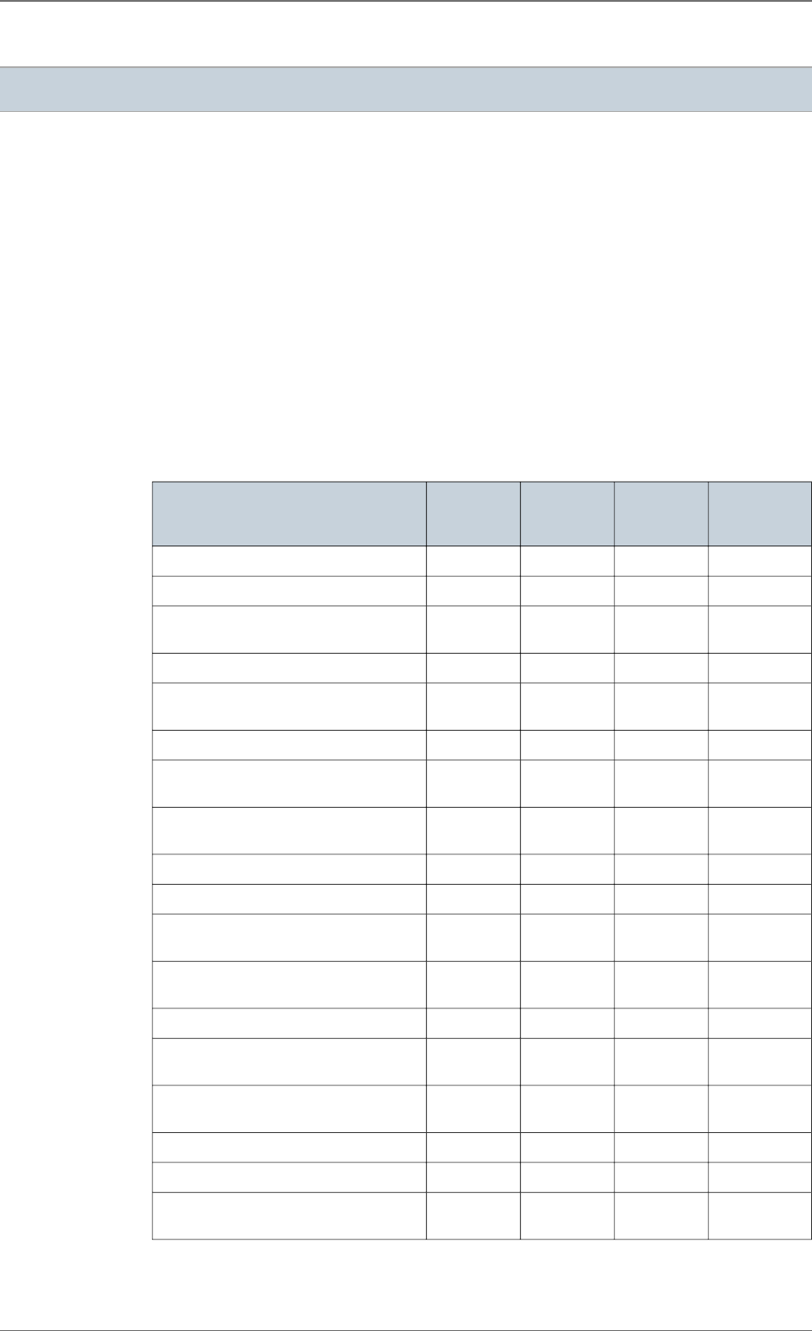
Device and lead connections:
1*IS4, 1*DF4, 1*SonR (IS-1 bipolar compatible)
1. GENERAL DESCRIPTION
8 SORIN – PLATINIUM 4LV SonR CRT-D 1844 – U906A

2. INDICATIONS
PLATINIUM 4LV SonR CRT-D 1844 is indicated for ventricular antitachycardia pacing and
ventricular defibrillation for automated treatment of life threatening arrhythmias.
The device is also indicated for the reduction of heart failure symptoms in medically optimized
NYHA Functional Class III and IV patients with left ventricular ejection fraction of 35% or less,
and a QRS duration of 150 ms or longer.
2. INDICATIONS
SORIN – PLATINIUM 4LV SonR CRT-D 1844 – U906A 9

3. CONTRAINDICATIONS
Implantation of PLATINIUM 4LV SonR CRT-D 1844 is contraindicated in patients:
― whose ventricular tachyarrhythmias may have transient or reversible causes such as:
acute myocardial infarction, digitalis intoxication, drowning, electrocution, electrolyte
imbalance, hypoxia, sepsis, or unstable ischemic episodes,
― who present incessant tachyarrhythmia,
― who have an internal pacemaker,
― whose primary disorder is bradyarrhythmias, or atrial tachyarrhythmias.
The use of the dual-chamber pacing mode is contraindicated in patients with chronic
refractory atrial tachyarrhythmias.
3. CONTRAINDICATIONS
10 SORIN – PLATINIUM 4LV SonR CRT-D 1844 – U906A

4. WARNINGS AND PRECAUTIONS
The patient should be warned of the potential risks of defibrillator malfunction if he is exposed
to external magnetic, electrical, or electromagnetic signals.
These potential interference sources may cause conversion to inhibited mode (because of
noise detection), erratic delivery of VT or VF therapies, nominal programming, or much more
rarely, irreversible damage to the device’s circuits.
The main sources of high magnitude disturbance are: powerful radiofrequency equipment
(radar), industrial motors and transformers, induction furnaces, resistance welding/ arc-
welding equipment and high power loudspeakers.
Electrical Isolation:
Do not permit the patient to contact grounded equipment that could produce hazardous
leakage current. Ensuing arrhythmia induction could result in the patient’s death.
Electronic Article Surveillance (EAS) and RadioFrequency IDentification
equipment (RFID)
Patients should be advised to walk directly through and not lean against or linger near
Electronic Article Surveillance (EAS) systems such as retail theft prevention systems,
security gates, entry control systems, or tag readers including Radio Frequency
IDentification equipment (RFID). These systems may be found at the entrances and exits of
stores, libraries, banks, etc...and may interact with pulse generators. It is unlikely that these
systems affect cardiac function when the patient walks through them at a normal pace. If
patients do experience symptoms near these systems, they should promptly move away and
inform their doctor.
Work environment:
The patient's work environment may be an important source of disturbance. In that case,
specific recommendations may be required.
High voltage power transmission lines:
High voltage power transmission lines may generate enough disturbance to interfere with
defibrillator operation if approached too closely.
Communication equipment:
Communication equipment such as microwave transmitters, linear power amplifiers, or high-
power amateur transmitters may generate enough disturbance to interfere with defibrillator
operation if approached too closely.
Home appliances:
Home appliances that are in good working order and properly grounded do not usually
produce enough disturbance to interfere with defibrillator operation. However, there are
reports of device interferences caused by electric hand tools or electric razors used directly
over the device implant site. Patient should also avoid using induction ovens and cookers.
4. WARNINGS AND PRECAUTIONS
SORIN – PLATINIUM 4LV SonR CRT-D 1844 – U906A 11

Cellular phones:
Radiofrequency signals can interfere with the functioning of the device if the handset is
placed too close to the pacemaker. It is advisable to maintain a minimum distance of 15 cm
(6 inches) between the cellular telephone and the implanted device, when the telephone is
turned on.
CAUTION: Do not tap sharply on the ICD can after implant, because the ICD's sensing
circuits can detect this as P-waves or R-waves, and such oversensing could result in
inappropriate pacing, inhibition, or therapy. Normal activities after implant do not result in
such oversensing.
RISKS RELATED TO MEDICAL ENVIRONMENT
It is advisable to carefully monitor defibrillator operation prior to and after any medical
treatment during which an electrical current from an external source passes through the
patient's body.
Magnetic Resonance Imaging:
MRI is contraindicated.
Radiofrequency ablation:
A radiofrequency ablation procedure in a patient with a generator may cause device
malfunction or damage. RF ablation risks may be minimized by:
1. Deactivating ATP and shock therapies.
2. Avoiding direct contact between the ablation catheter and the implanted lead or generator.
3. Positioning the ground, placing it so that the current pathway does not pass through or
near the device, i.e. place the ground plate under the patient’s buttocks or legs.
4. Having external defibrillation equipment available.
Electrocautery or diathermy device:
Diathermy and electrocautery equipment should not be used. If such devices must be used:
1. Keep the current path and ground plate as far away from the device and the leads as
possible (a minimum of 15 cm [six inches]).
2. Before procedure, deactivate ATP and shock therapies.
3. During the procedure, keep the electrocautery device as far as possible from the cardiac
defibrillator. Set it at minimum intensity. Use it briefly.
4. After the procedure, check for proper implant function. The device should never be
exposed directly to the diathermy source.
External defibrillation:
PLATINIUM 4LV SonR CRT-D 1844 is protected from external defibrillation shocks.
1. Before external defibrillation, deactivate ATP and shock therapies.
2. During external defibrillation, it is advisable to avoid placing the defibrillating paddles
directly over the casing or over the leads. The defibrillating paddles should preferably be
placed in an anteroposterior position.
3. Avoid any direct contact between the defibrillation paddles and the conductive parts of the
implanted leads or casing of the implanted device.
4. After external defibrillation, check for proper device function.
4.1.
4. WARNINGS AND PRECAUTIONS
12 SORIN – PLATINIUM 4LV SonR CRT-D 1844 – U906A

Radiation therapy:
Avoid exposure to ionizing radiation. Betatrons are contraindicated. If high doses of radiation
therapy cannot be avoided, the defibrillator should be protected from direct exposure with a
protection shield. ATP and shock therapies should be disabled during exposure and proper
device function should be checked regularly afterwards. Resulting damage may not be
immediately detectable. If irradiation of tissues close to the implantation site is necessary, it
is recommended that the cardiac defibrillator be moved. As a safety measure, an external
defibrillator should be immediately available.
Lithotripsy:
Lithotripsy may permanently damage the device if it is at the focal point of the lithotripsy
beam. If lithotripsy must be used, keep the defibrillator at least 2.5 to 5 cm (1-2 inches) away
from the focal point of the lithotripsy beam.
Diagnostic ultrasound (echography):
The defibrillator is not affected by ultrasound imaging devices.
Scales with body fat monitors and electronic muscle stimulators:
A patient with an implanted PLATINIUM 4LV SonR CRT-D 1844 should not use these
devices.
STERILIZATION, STORAGE AND HANDLING
Resterilization:
Do not resterilize and re-implant explanted ICDs.
"Use by" Date:
A "Use by" date is printed on the outer storage package and on the sterile package. Do
not implant the device after this date because the battery may have reduced longevity and
sterility may be affected. It should be returned to Sorin.
If Package is damaged:
Do not use the device or accessories if the packaging is wet, punctured, opened or damaged
because the integrity of the sterile packaging may be compromised. Return the device to the
manufacturer.
Device Storage:
Store the device in a clean area, away from magnets, kits containing magnets, and sources
of electromagnetic disturbance to avoid device damage. Store the device between 0 - 50 °C
(32 - 122 °F). Temperatures outside the specified range may damage the device.
Equilibration:
Allow the device to reach room temperature before programming or implanting the device
because rapid temperature changes may affect initial device function.
IMPLANTATION AND DEVICE PROGRAMMING
Use only a Sorin programmer to communicate with the device.
Do not inadvertently position any magnet over the ICD; this suspends tachyarrhythmia
detection and treatment.
Replace the device when the RRT (Recommended Replacement Time*) point (defined by a
battery voltage of 2.62 ± 0.01 V) is reached.
4.2.
4.3.
4. WARNINGS AND PRECAUTIONS
SORIN – PLATINIUM 4LV SonR CRT-D 1844 – U906A 13

Program device parameters such as sensitivity threshold and VT and VF detection intervals
as specified in the device manuals.
Lead System:
Do not use a lead system other than those with demonstrated compatibility because
undersensing cardiac activity and failure to deliver necessary therapy may result.
In situations where an ICD and a pacemaker are implanted in the same patient, interaction
testing should be completed. If the interaction between the ICD and the pacemaker cannot be
resolved through repositioning of the leads or reprogramming of either the pacemaker or the
ICD, the pacemaker should not be implanted (or should be explanted if previously implanted).
Failure to properly insert the torque screwdriver into the perforation at an angle perpendicular
to the connector receptacle may result in damage to the sealing system and its self-sealing
properties.
In the event of a warning on a low shock impedance, and after lead replacement or
reconnection: it is recommended to check the system integrity (sensing and pacing thresholds
and the impedance of the shock electrodes)
It is recommended that a safety margin of at least 10 J be demonstrated between the effective
shock energy and maximum programmable energy. Carefully confirm that true ventricular
fibrillation has been induced because the DFT for ventricular tachycardia or flutter may be
lower.
The defibrillator should be implanted with the engraved side facing outwards in order to
facilitate telemetric communication with the programming head and to display the
radiographic identification correctly.
*: corresponds to ERI (Elective Replacement Indicator) previously used.
LEAD EVALUATION AND LEAD CONNECTION
PLATINIUM 4LV SonR CRT-D 1844 has one DF4, one IS4, and one SonR connector ports.
The SonR connector port has been specifically designed by Sorin to accept three connections
(tripolar). The two distal connections respect the same dimensions as the IS-1 standard, and
an additional proximal connection allows to collect the SonR signal.
The SonR port accepts either a conventional atrial lead (without SonR capability) or a SonR
atrial lead (bipolar pacing/sensing and SonR capability).
IS-1 refers to the international standard whereby leads and generators from different
manufacturers are assured a basic fit (ISO 5841-3:2013).
DF4 and IS4 refer to the international standard for Four-pole connector systems for
implantable cardiac rhythm management devices (ISO 27186:2010).
Use only DF4-LLHH or DF4-LLHO standard lead connector types according to ISO
27186:2010.
Use only IS4-LLLL standard lead connector type according to ISO 27186:2010.
Do not tie a ligature directly to the lead body, tie it too tightly, or otherwise create excessive
strain at the insertion site as this may damage the lead. Use the lead stabilizer to secure the
lead lateral to the venous entry site.
Do not grip the lead with surgical instruments.
Do not use excessive force or surgical instruments to insert a stylet into a lead.
Use ventricular transvenous leads with caution in patients with either a mechanical or
bioprosthetic tricuspid valvular prosthesis.
4.4.
4. WARNINGS AND PRECAUTIONS
14 SORIN – PLATINIUM 4LV SonR CRT-D 1844 – U906A

Use the correct suture sleeve (when needed) for each lead, to immobilize the lead and protect
it against damage from ligatures.
The defibrillator can undergo a short-circuit if the anode and cathode are not adequately
separated.In this case, the shock is aborted and a warning will indicate that a short circuit
(shock impedance < 20 ohms) was detected during the last shock. The device may be
damaged compromising ability to provide shock therapy.
Do not kink leads. Kinking leads may cause additional stress on the leads, possibly resulting
in lead fracture.
Do not insert a lead connector pin into the connector block without first visually verifying that
the setscrews are sufficiently retracted. Do not tighten the setscrews unless a lead connector
pin is inserted because it could damage the connector block.
Lead electrodes in contact during a cardioversion or defibrillation therapy will cause current
to bypass the heart, possibly damaging the ICD and the leads. While the ICD is connected to
the leads, make sure that the metal portions of any electrodes do not touch each other.
If a pacing lead is abandoned rather than removed, it must be capped to ensure that it is not
a pathway for currents to or from the heart.
If a thoracotomy is required to place epicardial patches, it should be done during a separate
procedure to reduce the risk of morbidity and mortality.
Do not place the patch lead over nerve tissue as this may cause nerve damage.
Place the patch lead with the conducting coil side facing the heart to ensure delivery of energy
to the heart.
Place the sutures well outside the coil of the patch lead or in the area between the coils to
avoid possible coil fracture.
If countershock is unsuccessful using external paddles, adjust the external paddle position
(e.g., anterior-lateral to anterior-posterior) and be sure that the external paddle is not
positioned over the patch.
Do not fold, alter, or remove any portion of the patch as it may compromise electrode function
or longevity.
If a header port is unused on the generator, the port must be plugged to protect the generator.
GENERATOR EXPLANT AND DISPOSAL
Interrogate the device, and program shock therapy off prior to explanting, cleaning or shipping
the device to prevent unwanted shocks.
Return all explanted generators and leads to the manufacturer.
Never incinerate the device due to the potential for explosion. The device must be explanted
before cremation.
4.5.
4. WARNINGS AND PRECAUTIONS
SORIN – PLATINIUM 4LV SonR CRT-D 1844 – U906A 15
5. ADVERSE EVENTS
Clinical data presented in this section are from the MSP clinical study.
PLATINIUM 4LV SonR CRT-D 1844 is similar in design and function to the ALTO 2 MSP and
OVATIO CRT-D devices. The data provided are applicable to PLATINIUM 4LV SonR CRT-D
1844.
MSP STUDY
Sorin conducted an international, multi-center, randomized clinical trial of its cardiac
resynchronization therapy system. Investigators attempted to implant study devices in 190
patients. A total of 182 patients received study devices and had an exposure of over 165
device years. Of those patients, 19 received OVATIO CRT-D, 160 received ALTO 2 MSP, and
3 received ALTO MSP. The clinical data collected on ALTO MSP, ALTO 2 MSP and OVATIO
CRT-D are applicable to PLATINIUM 4LV SonR CRT-D 1844. The table below summarizes
the adverse events observed for the CRT-D system. No deaths were related to the system.
Event # of Pa-
tients
% of Pa-
tients
# of
Events
Events/100
Device-
Years
Deaths not related to the system 16 8.4 16 0.8
Cardiac arrest 5 2.6 5 0.3
Worsening CHF / CHF decompensa-
tion
3 1.6 3 0.2
Multi-organ dysfunction 2 1.1 2 0.1
Complications related to the sys-
tem
28 14.7 35 2.1
Dislodgment or migration 9 4.7 11 0.6
Extracardiac stimulation (e.g., phrenic
stim)
9 4.7 9 0.5
Complications related to the im-
plant procedure
18 9.5 21 1.3
Dislodgment or migration 4 2.1 4 0.2
Observations related to the system 23 12.1 27 1.7
Extracardiac stimulation (e.g., phrenic
stim)
12 7.9 15 0.8
Observations related to the implant
procedure
24 12.6 28 1.7
Heart block 6 3.2 6 0.3
Extracardiac stimulation (e.g., phrenic
stim)
3 1.5 5 0.3
Serious adverse events not related
to the system
85 44.7 176 10.8
Worsening CHF/CHF decompensation 24 12.6 42 2.1
Atrial fibrillation/flutter 14 7.4 14 0.7
Not Serious events not related to
the system
58 30.5 121 7.4
5.1.
5. ADVERSE EVENTS
16 SORIN – PLATINIUM 4LV SonR CRT-D 1844 – U906A

Event # of Pa-
tients
% of Pa-
tients
# of
Events
Events/100
Device-
Years
Pain (in back, arms, chest, shoulder,
groin, head, other)
10 5.3 13 0.7
Worsening CHF/CHF decompensation 13 6.8 16 0.8
Atrial fibrillation/flutter 7 3.7 8 0.4
Ventricular tachycardia 7 3.7 7 0.4
POTENTIAL ADVERSE EVENTS
Adverse events (in alphabetical order), including those reported in the previous tables,
associated with ICD systems include:
― Acceleration of arrhythmias (caused by device),
― Air embolism,
― Bleeding,
― Chronic nerve damage,
― Erosion,
― Excessive fibrotic tissue growth,
― Extrusion,
― Fluid accumulation,
― Formation of hematomas or cysts,
― Inappropriate shocks,
― Infection,
― Keloid formation,
― Lead abrasion and fracture,
― Lead migration/dislodgment,
― Myocardial damage,
― Pneumothorax,
― Shunting current or insulating myocardium during defibrillation with internal or external
paddles,
― Potential mortality due to inability to defibrillate or pace,
― Thromboemboli,
― Venous occlusion,
― Venous or cardiac perforation.
Patients susceptible to frequent shocks despite antiarrhythmic medical management may
develop psychological intolerance to an ICD system that may include the following:
― Dependency,
― Depression,
― Fear of premature battery depletion,
― Fear of shocking while conscious,
― Fear that shocking capability may be lost,
― Imagined shocking (phantom shock).
5.2.
5. ADVERSE EVENTS
SORIN – PLATINIUM 4LV SonR CRT-D 1844 – U906A 17

6. CLINICAL STUDIES
Clinical data presented in this section are from the MSP clinical study. PLATINIUM 4LV SonR
CRT-D 1844 is similar in design and function to the ALTO 2 MSP and OVATIO CRT-D devices.
The data provided are applicable to PLATINIUM 4LV SonR CRT-D 1844.
MSP CLINICAL STUDY
OVATIO CRT-D and earlier models were evaluated clinically in an international, multi-center,
randomized clinical trial of Sorin’s cardiac resynchronization therapy (CRT-D) system.
Investigators attempted to implant study devices in 190 patients. A total of 182 patients
received study devices and had an exposure of over 165 device years. Of those patients, 19
received OVATIO CRT-D, 160 received ALTO 2 MSP, and 3 received ALTO MSP.
Objectives
The primary objectives of the study were to demonstrate:
― Greater improvement in a composite endpoint (percent improvement in peak VO2
percent improvement in quality of life) for CRT-D patients than for control patients.
― System complication-free rate ≥ 67 % at six months.
Methods
Patients were New York Heart Association class III or IV and had one or more indications for
an implantable cardioverter defibrillator (ICD). Patients performed cardiopulmonary exercise
testing at baseline and six-months after randomization. Patients were implanted with a Sorin
ICD with CRT-D, a Situs UW28D left ventricular lead, and commercially available right atrial
and ventricular leads. Routine follow-ups were at pre-discharge, randomization (3-14 days
post-implant), one month, three months, and six months post randomization.
Results
Improvement in composite endpoint
Patients were included in the analysis if complete (peak VO2and quality of life) baseline and
six-month data were available.
Number of
patients
contributing
to analysis
Mean percent im-
provement in com-
posite endpoint for
control group
Mean percent im-
provement in com-
posite endpoint for
CRT-D group
Percent
greater im-
provement
for CRT-D
group
p-
value
132 15.5 % 24.9 % 9.4 % 0.046
Six-month system complication-free rate
Number of patients
contributing to
analysis
Kaplan-Meier six-month
complication-free esti-
mate
One-sided lower 95% confidence
bound for six-month complication-free
estimate
190 89.5 % 84.1 %
6.1.
6.1.1.
6.1.2.
6.1.3.
6. CLINICAL STUDIES
18 SORIN – PLATINIUM 4LV SonR CRT-D 1844 – U906A

Absolute Differences in Peak VO2and QOL
The tables below show the absolute differences between the control and test groups’ peak
VO2and QOL over the 6 month follow-up period in the clinical trial.
Absolute difference between test and control groups’ change in peak V02over 6
months
Baseline
Mean ± SD
(range)
6-month
Mean ± SD
(range)
Difference
within
group
Difference
between
groups
Control
group
(n=41)
13.39 ± 4.58
(5.02, 24.10)
13.12 ± 3.99
(3.30, 20.70)
- 0.28 1.85Change in Peak
VO2
(mL/min/Kg)
Test
group
(n=91)
11.84 ± 3.90
(3.50, 26.3)
13.41 ± 4.28
(6.18, 27.67)
1.57
Absolute difference between test and control groups’ change in QOL score over
6 months
Baseline
Mean ± SD
(range)
6-month
Mean ± SD
(range)
Difference
within
group
Difference be-
tween groups
Control
group
(n=41)
47.5 ± 19.29
(9, 90.3)
31.21 ± 23.96
(0, 95)
16.29 1.28Change
in QOL
Test
group
(n=91)
52.81 ± 21.84
(9, 92)
35.24 ± 23.73
(0, 93)
17.57
The table below presents the percentage of patients in each group who improved, worsened,
or remained unchanged in each element of the composite score and the composite score
itself.
QOL score VO2Score Composite Score
Control
GROUP
Test
GROUP
Control
GROUP
Test
GROUP
Control
GROUP
Test
GROUP
% Im-
proved
75.6 74.7 48.8 67.0 62.2 70.9
% Wors-
ened
24.4 25.3 51.2 31.9 37.8 28.6
% Un-
changed
0.0 0.0 0.0 1.1 0.0 0.0
Histograms for Respiratory Exchange Rate (RER) at peak VO2at baseline and 6 month
follow-up are provided below:
6.1.4.
6. CLINICAL STUDIES
SORIN – PLATINIUM 4LV SonR CRT-D 1844 – U906A 19
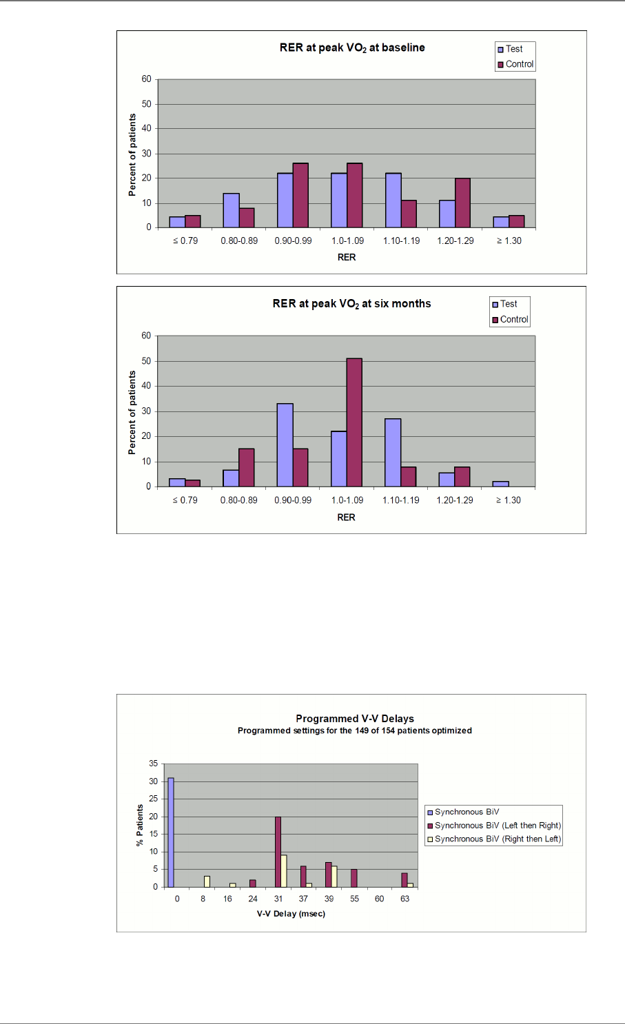
Clinical Results V-V timing
V-V programmable settings were available for the clinical study devices as follows: ALTO
MSP model 617 (not programmable for V-V delay), ALTO 2 MSP model 627 values (0, 31,
39, 47, 55 and 63 ms) and OVATIO CRT-D 6750 values (0 to 63 ms in steps of 8 ms).
The graph below shows the programmed V-V settings at randomization by percentage of
patients programmed to each combination of Synchronous BiV pacing and V-V delay.
The optimization protocol in the clinical study specified that each patient randomized should
undergo echo guided V-V optimization. Per the investigational plan for the MSP Clinical
6.1.5.
6. CLINICAL STUDIES
20 SORIN – PLATINIUM 4LV SonR CRT-D 1844 – U906A

Trial, a uniform protocol was used for V-V programming. This protocol required all patients
to undergo echo-guided V-V delay optimization before randomization (2 to 14 days post-
implant). The optimal V-V delay was determined by finding the programmable V-V delay and
ventricular chamber pacing order (RV then LV, or LV then RV) providing the maximum time
velocity integral (TVI or VTI) across the left ventricular outflow tract (LVOT).
Only those patients randomized to the Test arm were required to be programmed per the
optimization protocol for the V-V delay.
Of the 177 patients that presented at randomization, 3 had Model 617 which does not have
V-V programmability hence the inability to optimize. Of the remaining 174 patients, 154
(89%) were tested per the V-V optimization protocol. One hundred forty-nine (149) of the
154 patients who were tested per the V-V optimization protocol were programmed per the
recommended or randomized V-V delay (97%). Thirty-one (31) patients were programmed
to BiV synchronous (V-V delay 0ms), 46 were programmed to Sequential BiV (LV then
RV), 22 were programmed to Sequential (RV then LV), and the remaining 50 patients were
randomized to RV only.
A sub-analysis of the composite endpoint comparing the subset of CRT-D patients with
optimized V-V delays vs. the subset of patients that did not undergo V-V delay optimization
demonstrated similar results in both groups. The CRT-D patients who did not undergo V-V
delay optimization showed a smaller improvement in the composite endpoint, although the
sample size did not permit conclusions based on data from this subset.
6. CLINICAL STUDIES
SORIN – PLATINIUM 4LV SonR CRT-D 1844 – U906A 21

7. PATIENT SELECTION AND TREATMENT
INDIVIDUALIZATION OF TREATMENT
Exercise stress testing:
If the patient’s condition permits, use exercise stress testing to:
― Determine the maximum rate of the patient’s normal rhythm,
― Identify any supraventricular tachyarrhythmias,
― Identify exercise-induced tachyarrhythmias.
The maximum exercise rate or the presence of supraventricular tachyarrhythmias may
influence selection of programmable parameters. Holter monitoring or other extended ECG
monitoring also may be helpful.
CAUTION: To avoid inappropriate therapy during an exercise stress test, do not reprogram
any parameter during the test. When a parameter is reprogrammed, algorithm forces
acceleration to "ventricular". During conducted sinus tachycardia within the programmed
Tachy zone, the device detects a 1:1 fast rhythm. Assuming that acceleration was set to
ventricular by reprogramming, the device may identify this as a VT, and may immediately
apply the corresponding therapy.
Electrophysiologic (EP) testing:
EP testing may be useful for ICD candidates.
EP testing may identify the classifications and rates of all the ventricular and atrial
arrhythmias, whether spontaneous or during EP testing.
Drug resistant supraventricular tachyarrhythmias (SVTs):
Drug resistant supraventricular tachyarrhythmias (SVTs) may initiate frequent unwanted
device therapy.
A careful choice of programming options is necessary for such patients.
Antiarrhythmic drug therapy:
If the patient is being treated with antiarrhythmic or cardiac drugs, the patient should be on a
maintenance drug dose rather than a loading dose at the time of ICD implantation. If changes
to drug therapy are made, repeated arrhythmia inductions are recommended to verify ICD
detection and conversion. The ICD also may need to be reprogrammed.
Changes in a patient’s antiarrhythmic drug or any other medication that affects the patient’s
normal cardiac rate or conduction can affect the rate of tachyarrhythmias and/or efficacy of
therapy.
Direct any questions regarding the individualization of patient therapy to Sorin’s
representative.
SPECIFIC PATIENT POPULATIONS
Pregnancy:
If there is a need to image the device, care should be taken to minimize radiation exposure
to the fetus and the mother.
7.1.
7.2.
7. PATIENT SELECTION AND TREATMENT
22 SORIN – PLATINIUM 4LV SonR CRT-D 1844 – U906A

Nursing Mothers:
Although appropriate biocompatibility testing has been conducted for this implant device,
there has been no quantitative assessment of the presence of leachables in breast milk.
Pediatric Patients:
This device has not been studied in patients younger than 18 years of age.
Geriatric Patients:
Most of the patients receiving this device in clinical studies were over the age of 60 years.
Handicapped and Disabled Patients:
Special care is needed in using this device for patients using an electrical wheel chair or
other electrical (external or implanted) devices.
7. PATIENT SELECTION AND TREATMENT
SORIN – PLATINIUM 4LV SonR CRT-D 1844 – U906A 23

8. PATIENT COUNSELLING INFORMATION
The physician should consider the following points in counselling the patient about this
device:
― Persons administering CPR may experience tingling on the patient’s body surface when
the patient’s ICD system delivers a shock.
― Advise patients to carry Sorin ID cards and/or ID bracelets documenting their ICD
system.
8. PATIENT COUNSELLING INFORMATION
24 SORIN – PLATINIUM 4LV SonR CRT-D 1844 – U906A
9. DECLARATION OF CONFORMITY
Sorin declares that this device is in conformity with the essential requirements of Directive
1999/5/EC on Radio and Telecommunications Terminal Equipment, with the mutual
recognition of their conformity (R&TTE).
Federal Communication Commission Interference Statement 47 CFR Section 15.19 and
15.105(b)
The FCC product ID is :
―PLATINIUM 4LV SonR CRT-D 1844: YSGCRTDSOR1844
This equipment has been tested and found to comply with the limits for a Class B digital
device, pursuant to Part 15 of the FCC Rules. These limits are designed to provide
reasonable protection against harmful interference in a residential installation. This
equipment generates, uses and can radiate radio frequency energy and, if not installed
and used in accordance with the instructions, may cause harmful interference to radio
communications. However, there is no guarantee that interference will not occur in a particular
installation.
This device complies with Part 15 of the FCC Rules. Operation is subject to the following
two conditions: (1) This device may not cause harmful interference, and (2) this device must
accept any interference received, including interference that may cause undesired operation.
FCC Interference Statement 47 CFR Section 15.21 - No Unauthorized Modifications
CAUTION: This equipment may not be modified, altered, or changed in any way without
signed written permission from SORIN. Unauthorized modification may void the equipment
authorization from the FCC and will void the SORIN warranty.
Identification of the equipment according Section 95.1217(a)
This transmitter is authorized by rule under the Medical Device Radiocommunication Service
(in part 95 of the FCC Rules) and must not cause harmful interference to stations operating
in the 400.150-406.00 MHz band in the Meteorological Aids (i.e., transmitters and receivers
used to communicate weather data), the Meteorological Satellite, or the Earth Exploration
Satellite Services and must accept interference that may be caused by such stations,
including interference that may cause undesired operation. This transmitter shall be used
only in accordance with the FCC Rules governing the Medical Device Radiocommunication
Service. Analog and digital voice communications are prohibited. Although this transmitter
has been approved by the Federal Communications Commission, there is no guarantee that
it will not receive interference or that any particular transmission from this transmitter will be
free from interference.
IC Requirements for Canada
The IC product ID is :
―PLATINIUM 4LV SonR CRT-D 1844: 10270A-CRTDSOR1844
This class B digital apparatus meets all requirements of the Canadian Interference- causing
equipment regulations.
This device complies with Industry Canada licence-exempt RSS standard(s). Operation is
subject to the following two conditions: (1) this device may not cause interference, and (2)
9. DECLARATION OF CONFORMITY
SORIN – PLATINIUM 4LV SonR CRT-D 1844 – U906A 25

this device must accept any interference, including interference that may cause undesired
operation of the device.
Under Industry Canada regulations, this radio transmitter may only operate using an antenna
of a type and maximum (or lesser) gain approved for the transmitter by Industry Canada.
To reduce potential radio interference to other users, the antenna type and its gain should
be so chosen that the equivalent isotropically radiated power (e.i.r.p.) is not more than that
necessary for successful communication.
This device may not interfere with stations operating in the 400.150–406.000 MHz band in
the Meteorological Aids, Meteorological Satellite, and Earth Exploration Satellite Services
and must accept any interference received, including interference that may cause undesired
operation.
Cet appareil numérique de la classe B respecte toutes les exigences du règlement sur le
matériel brouilleur du Canada.
Le présent appareil est conforme aux CNR d’Industrie Canada applicables aux appareils
radio exempts de licence. L’exploitation est autorisée aux deux conditions suivantes: (1) il
ne doit pas produire de brouillage, et (2) l’utilisateur du dispositif doit être prêt a accepter
tout brouillage radioélectrique reçu, même si ce brouillage est susceptible de compromettre
le fonctionnement du dispositif.
Conformément à la réglementation d’Industrie Canada, le présent émetteur radio peut
fonctionner avec une antenne d’un type et d’un gain maximal (ou inférieur) approuvé pour
l’émetteur par Industrie Canada. Dans le but de réduire les risques de brouillage
radioélectrique à l’ intention d’autres utilisateurs, il faut choisir le type d’antenne et son gain
de sorte que la puissance isotrope rayonnée équivalente (p.i.r.e.) ne dépasse pas l’intensité
nécessaire à l’établissement d’une communication satisfaisante.
Le présent dispositif ne doit pas causer de brouillage aux stations du service des auxiliaires
de la météorologie, des satellites météorologiques, du service d’exploration de la terre par
satellite, exploitées dans la bande 400,150-406,000 MHz, et il doit accepter tout brouillage
reçu, y compris le brouillage pouvant entraîner un mauvais fonctionnement du dispositif.
9. DECLARATION OF CONFORMITY
26 SORIN – PLATINIUM 4LV SonR CRT-D 1844 – U906A

10. PHYSICIAN GUIDELINES
PHYSICIAN TRAINING
Physicians should be familiar with sterile pulse generator and left ventricular pacing lead
implant procedures. They must apply these procedures according to professional medical
training and experience.
Physicians should be familiar with follow-up evaluation and management of patients with an
implantable defibrillator (or referral to such a physician).
This training guideline for implantation and follow-up of ICD and CRT-D devices comes
from the Heart Rhythm Society to provide standards for hospital credentialing bodies to
help ensure appropriate patient care and lead to improved patient outcomes. The following
is a summary of requirements for an alternate training pathway for ICD and CRT-D
implantations(1):
― Documentation of current experience: 35 pacemaker implantations per year and 100
implantations over the prior 3 years
― Proctored ICD implantation experience: 10 Implantations, 5 Revisions
― Proctored CRT-D implantation experience: 5 implantations
― Completion of didactic course and/or IBHRE® ExAM
― Monitoring of patient outcomes and complication rates
― Established patient follow-up
― Maintenance of competence: 10 ICD and CRT-D procedures per year, 20 patients per
year in follow-up
(1) Please consult full text of both publications for details. 2004 Heart Rhythm Society Clinical
Competency Statement and the 2005 Addendum on Training Pathways for Implantation of
Cardioverter Defibrillators and Cardiac Resynchronization Devices. Heart Rhythm (2004) 3,
371-375; Heart Rhythm.
DIRECTIONS FOR USE
ICD operating characteristics should be verified at the time of implantation and recorded in
the patient file. Complete the Patient Registration Form and return it to Sorin, as it provides
necessary information for warranty purposes and patient tracking.
Additional programming instructions can be found by accessing Online Help (click the “?” on
the screen) on the Sorin dedicated programmer. Paper copies of Online Help can be obtained
by contacting your Sorin representative.
MAINTAINING DEVICE QUALITY
This device is FOR SINGLE USE ONLY. Do not resterilize and reimplant explanted ICDs.
Do not implant the device when:
― It has been dropped on a hard surface because this could have damaged pulse
generator components.
― Its sterility indicator within the inner package is not green, because it might not have been
sterilized.
10.1.
10.2.
10.3.
10. PHYSICIAN GUIDELINES
SORIN – PLATINIUM 4LV SonR CRT-D 1844 – U906A 27

― Its storage package has been pierced or altered, because this could have rendered it
non-sterile.
― It has been stored or transported outside the environmental temperature limits: 32 °F (0
°C) to 122 °F (50 °C) as an electrical reset condition may occur.
― "Use by" date has expired, because this can adversely affect pulse generator longevity
or sterility.
V-V PROGRAMMING RECOMMENDATION
It is recommended that V-V optimization testing be performed and used to set the V-V delay
for this device to optimize the potential for RF SonR CRT-D benefit to the patient.
10.4.
10. PHYSICIAN GUIDELINES
28 SORIN – PLATINIUM 4LV SonR CRT-D 1844 – U906A

11. PATIENT INFORMATION
Information for the patient is available in the patient booklet, contained in the outer storage
package. Additional copies can be obtained by contacting your Sorin representative.
This information should be given to each patient with their first ICD and offered to the patient
on each return visit or as deemed appropriate.
11. PATIENT INFORMATION
SORIN – PLATINIUM 4LV SonR CRT-D 1844 – U906A 29

12. HOW SUPPLIED
STERILITY
The PLATINIUM defibrillators are supplied one per package in a sterile package.
WARRANTY AND REPLACEMENT POLICY
Sorin warrants its defibrillators. Refer to the section "Warranty" for additional information.
Please see the following labelling sections for information concerning the performance of this
device: Indications, Contraindications, Warnings and Precautions, and Adverse Events.
12.1.
12.2.
12. HOW SUPPLIED
30 SORIN – PLATINIUM 4LV SonR CRT-D 1844 – U906A

13. DEVICE DESCRIPTION
The PLATINIUM 4LV SonR CRT-D 1844 ICD device and programming system. The
programming system includes the Sorin dedicated programmer with the SMARTVIEW
programming software connected to a CPR3 programming head. The programming system
is configured and furnished by Sorin.
The PLATINIUM 4LV SonR CRT-D 1844 can serve as a defibrillation electrode (active
housing) with a total surface area of 62.4 cm².
The PLATINIUM 4LV SonR CRT-D 1844 is designed to recognize and treat slow or fast
VT and VF by continuously monitoring atrial and ventricular activity to identify persistent
ventricular arrhythmias and to deliver appropriate therapies. PLATINIUM 4LV SonR CRT-D
1844 features the PARAD/PARAD+ algorithm, which is specifically designed to differentiate
ventricular tachycardias from fast rhythms of supraventricular origin. PARAD/PARAD+
continuously monitors R-R interval stability, searches for long cycles, assesses the degree
of P-R association, evaluates sudden onset and determines the chamber of arrhythmia
acceleration.
In addition to the advanced detection scheme, PLATINIUM 4LV SonR CRT-D 1844 offers
programmable single, dual or triple-chamber pacing therapy (DDD, DDI, VVI or SafeR
(AAI <> DDD) modes) with or without rate-responsive capabilities (DDDR, DDIR, VVIR,
DDD/DDIR and SafeR-R (AAIR <> DDDR) modes) using an acceleration sensor. An
automatic AV delay algorithm as well as a mode switching function are available.
PLATINIUM 4LV SonR CRT-D 1844 enables an adjustment of the interventricular delay,
and provides the possibility of adapting pacing to each ventricle. The ICD is intended
to resynchronize uncoordinated contraction of the heart by simultaneously or sequentially
pacing both ventricles.
PLATINIUM 4LV SonR CRT-D 1844 features simultaneous multipoint left ventricular pacing
allowing LV pacing on 2 differents vectors at the same time.
PLATINIUM 4LV SonR CRT-D 1844 offers tiered therapy. Therapies can be programmed
independently in each zone:
― in the Slow VT and VT zones: two ATP programs, up to two shocks with programmable
energy and up to four shocks with maximum energy can be programmed;
― in the VF zone: one ATP program, up to two shocks with programmable energy and up
to four shocks with maximum energy can be programmed.
The ATP can be applied in RV, LV or RV and LV pacing with a VV delay equal to 0 ms. ATP
pacing configuration is independent of ventricular pacing configuration.
When the rhythm changes from one zone to another, the device delivers the therapy
programmed in this zone, starting with the same or more aggressive program for the zone.
The ATP program in the VF zone will only be applied if the VT coupling interval is longer than
the programmed fast VT cycle length.
The PLATINIUM 4LV SonR CRT-D 1844 offers biphasic shocks with a maximum stored
energy of 42 J. The shock configuration (electrodes used to apply the shock) can be chosen
by programming one of the following combinations: can and one coil, can and two coils, two
coils only.
Other features are as follows:
― Automatic ventricular sensitivity control
13. DEVICE DESCRIPTION
SORIN – PLATINIUM 4LV SonR CRT-D 1844 – U906A 31

― Non-committed shocks
― Electrophysiological studies (EPS) with real-time markers or electrograms:
― Programmer-controlled VT induction sequences,
― Programmer-controlled VF inductions (30 Hz rapid pacing or shock on T),
― Programmable electrogram vectors (A / RAring –CAN / RVcoil – CAN / RVtip – CAN
/ RVring – CAN/ RVcoil – SVC / SVC – CAN / LVtip1 - LV2 / LVtip1 - RVring / LVtip1
– LV4 / LVtip1 – CAN / LV2 - CAN / LV3 – LV2 / LV3- RVring / LV3 - LV4 / LV3 – CAN
/ LV2-LV4 / LV4 – CAN) and RV EGM,
― Real-time annotations displayed with the markers and indicating the majority rhythm,
― Manual ATP sequences,
― Manual shocks.
― Rescue shock
― Follow-up tests:
― Pacing lead impedance,
― Coil impedance,
― Capacitor charge time,
― Sensitivity test,
― Pacing threshold tests.
― Data storage:
― Therapy History Report,
― Statistics (pace/sense, therapy, shocks, and battery voltage),
― Up to 10 episodes and 5 min EGM on significant events: AV block switch, lead
impedance out of range,
― Up to 16 complete Holter records with event logs, marker channel notation, and
electrogram records.
The PLATINIUM 4LV SonR CRT-D 1844 connector head has three ports:
― Atrial “SonR” port: performs atrial bipolar pace/sense if a conventional IS-1 lead is
connected as well as SonR capability if the SonR atrial lead is connected,
― LV “IS4” port: performs left ventricular pace,
― RV “DF4” port: performs right ventricular bipolar pace/sense, port for RV/SVC
defibrillation coils.
Distal lead terminal connections are secured with set-screws accessed via self-sealing
silicone plugs. All lead connections pass through the header into the device via feedthroughs.
Programming System:
The Sorin programmer is used in conjunction with specific programmer software to
interrogate and program the implanted device at implant and during patient follow-up
procedures.
Remote Monitoring:
PLATINIUM 4LV SonR CRT-D 1844 is also equipped with the RF wireless technology which
enables to remotely monitor the patients who have the Sorin SMARTVIEW Monitor installed
at home.
13. DEVICE DESCRIPTION
32 SORIN – PLATINIUM 4LV SonR CRT-D 1844 – U906A

14. IMPLANT PROCEDURE
NECESSARY EQUIPMENT
Implantation of PLATINIUM 4LV SonR CRT-D 1844 requires the following equipment:
― Sorin ORCHESTRA programmer, equipped with the SMARTVIEW software interface
and inductive telemetry head,
― Sorin ORCHESTRA PLUS programmer, equipped with the SMARTVIEW software
interface, inductive telemetry head and optionally ORCHESTRA PLUS LINK,
― pacing system analyzer, as well as its sterile connecting cables, to evaluate the pacing
and sensing thresholds,
― a complete set of leads with corresponding introducers,
― physiological signal monitor capable of displaying simultaneously the surface ECG and
arterial pressure,
― an external defibrillator with sterile external paddles,
― sterile cover for the telemetry head.
NOTE: In case you are implanting a DF4 and/or IS4 lead(s), please verify its compatibility
with standard alligators pin; please refer to the lead user’s manual for more details.
PACKAGING
Contents
PLATINIUM 4LV SonR CRT-D 1844 and its accessories are ethylene oxide sterilized and
hermetically sealed in two-ply clear packaging meeting international requirements.
The sterile packaging contains:
― the defibrillator
― a ratcheting screwdriver
As delivered, PLATINIUM 4LV SonR CRT-D 1844 is programmed to as-shipped values that
are different from nominal values (see Chapter “Programmable Parameters” for details).
OPTIONAL EQUIPMENT
The following equipment may be required during implantation of PLATINIUM 4LV SonR CRT-
D 1844:
― an IS-1 insulating plug to close the atrial port
― sterile water to clean traces of blood. Any parts cleaned with sterile water must be
thoroughly dried.
― mineral oil to lubricate if necessary
― a lead cap to isolate a lead which is not used
14.1.
14.2.
14.2.1.
14.3.
14. IMPLANT PROCEDURE
SORIN – PLATINIUM 4LV SonR CRT-D 1844 – U906A 33

BEFORE OPENING THE PACKAGE
Before opening the package, check the "Use by" date printed on the labels on the box and
on the sterile package. Defibrillators that have not been implanted by the end of the “Use by”
date should be returned to Sorin.
Interrogate the device:
― if a warning is displayed, do not implant the device and contact your Sorin representative.
― if battery voltage is below 3V, and if the last reforming/charge occurred more than one
week ago, do not implant the device. Otherwise, wait for one more week before checking
the voltage.
NOTE : The battery voltage can decrease before the expiration date is reached. However,
the battery voltage should be equal to or higher than 3V at the time of implant.
When using the inductive wand, devices MUST NOT be interrogated and/or programmed
within the vicinity of other devices.
Also check the integrity of the sterile package. The sterility of the contents is no longer
guaranteed if the package has been pierced or altered. If the defibrillator is no longer sterile, it
should be returned in its packaging to Sorin. Any re-sterilization of the unit is at the discretion
of Sorin.
PRIOR TO IMPLANTATION
Use the programmer to verify the defibrillator can be interrogated before implantation.
Verify all shock therapies are disabled in order to avoid accidental discharge during
implantation.
It is not advisable to program the Smoothing function before implantation, since the
defibrillator may detect noise and pace at a rate higher than the programmed basic rate.
CAUTION:
Do not shake or tap sharply on the ICD package with the ICD inside, because the ICD's
sensing circuits can interpret this as P-waves or R-waves and record these as an arrhythmia
episode.
High voltage capacitors charge performed on ICD without connected leads using wireless
telemetry can generate false P-waves or R-waves detection.
It is recommended to reset the memory data and statistics before implanting the ICD.
DEVICE PLACEMENT
The pocket should be prepared in the left pectoral position, either subcutaneously or
submuscularly. Subcutaneous device implantation is recommended for optimal RF
communication efficacy.
Implantation in an abdominal position is not advisable.
In its final position, the defibrillator should be no more than 4 cm (1.6 in) below the skin
surface.
CHOOSING THE TYPE OF LEAD
The defibrillator should be connected to:
― one bipolar atrial sensing/pacing lead with or without dedicated SonR sensor
14.4.
14.5.
14.6.
14.7.
14. IMPLANT PROCEDURE
34 SORIN – PLATINIUM 4LV SonR CRT-D 1844 – U906A

― one DF4 right ventricular lead with bipolar sensing/pacing electrodes and one or two
defibrillation coils (DF4-LLHO or DF4-LLHH)
― one IS4-LLLL left ventricular pacing lead
The choice of leads and their configuration is left to the implanting physician’s judgment.
Replacement of an existing atrial lead:
If the initial lead which was connected to the atrial port of the PLATINIUM 4LV SonR CRT-D
1844 was not a SonR lead (i.e. a conventional lead or plug), then do not implant a SonR lead
as replacement; possible blood infiltration at the entrance of the connector port may prevent
proper measurement of the SonR signal.
NOTE1: Please note that in the event of defibrillator replacement, DF-1 standard compliant
lead is not compatible with DF4 connector and DF4 standard compliant lead is not
compatible with DF-1 connector. Choose the appropriate device compatible with DF-1 or
DF4 leads. For any other lead type that requires an adaptor for this device, please contact
your Sorin representative for any information on lead / connector compatibility question.
NOTE2: Please note that in the event of defibrillator replacement, IS-1 standard compliant
lead is not compatible with IS4 connector. Choose the appropriate device compatible with
IS-1 or IS4 leads. For any other lead type that requires an adaptor for this device, please
contact your Sorin representative for any information on lead / connector compatibility
question.
NOTE3: In the event that no atrial lead is implanted, the atrial port should be plugged with
IS-1 insulating plug and a single chamber mode (VVI-VVIR) should be programmed. PARAD
and PARAD+ should not be used.
NOTE4: In the event of a warning on a low shock impedance, and after lead replacement
or reconnection: it is recommended to check the system integrity (sensing and pacing
thresholds and the impedance of the shock electrodes).
Connectors:
The atrial connector is compatible with the IS-1 standard.
The quadripolar right ventricular connector is compatible with the DF4 standard and the
quadripolar left ventricular connector is compatible with the IS4 standard.
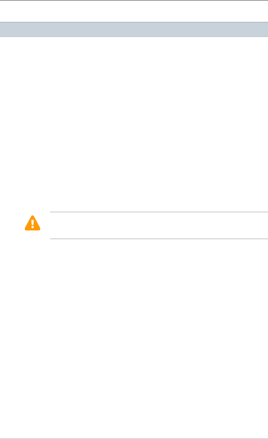
SHOCK CONFIGURATION (+ -> -)
The shock configuration is the energy pathway between the defibrillation electrodes. If an
atrial coil (SVC) is present, the shock configuration can be programmed for bi-directional
shocks.
Programming:
When active case and atrial coil (SVC) are both programmed to Yes, the shock configuration
can be programmed to:
― RV to Case (or Case to RV),
― or RV to SVC (or SVC to RV),
― or RV to Case+SVC (or Case+SVC to RV).
14.8.
14. IMPLANT PROCEDURE
SORIN – PLATINIUM 4LV SonR CRT-D 1844 – U906A 35
RV to Case+SVC RV to Case RV to SVC
The polarity of shock is determined by the parameter itself.
MEASUREMENT OF THRESHOLDS AT IMPLANT
Pacing and sensing thresholds should be measured at implant.
Pacing thresholds:
Acute thresholds should be lower than 1 V (or 2 mA) for a 0.35 ms pulse width, in both
ventricles and in the atrium.
Sensing thresholds:
For appropriate right ventricular sensing, the amplitude of the R-wave should be greater than
5 mV.
For appropriate atrial sensing, the amplitude of the P-wave should be greater than 2 mV.
Pacing impedance measurements:
Right ventricular, left ventricular and atrial pacing impedances should range from 200 to 3000
ohms (refer to the lead characteristics, especially if high impedance leads are used).
Please refer to the leads user manuals for more details on the expected electrical
performances of the leads.
LEADS CONNECTION
Implant the ventricular leads, then the atrial lead.
Each lead must be connected to the corresponding connector port. The position of each
connector is indicated on the casing.
CAUTION:
Tighten only the distal inserts.
To connect each lead, proceed as follows:
1. Clean the lead terminal pins thoroughly, if necessary (device replacement).
2. Lubricate the lead terminal pins with sterile water, if necessary.
3. Do not insert a lead connector pin into the connector block without first visually verifying
that the lead port is not obstructed.
4. Insert the screwdriver into the pre-inserted screw socket of the appropriate port (in order
to allow excess air to bleed out and to make the insertion of the lead pin easier).
5. Insert the lead pin all the way into the port (check that the pin protrudes beyond the distal
connector block).
14.9.
14.10.
14. IMPLANT PROCEDURE
36 SORIN – PLATINIUM 4LV SonR CRT-D 1844 – U906A
6. Tighten, check the tightness and ensure the lead pin still protrudes beyond the distal
connector block, and has not moved.
CAUTION:
1. Do not tighten the pre-inserted screws when there is no lead (this could damage the
connector).
2. Do not loosen the screws before inserting the connector (subsequent risk of being unable
to reinsert the screw).
3. When mineral oil or sterile water is used to make lead insertion easier, the screwdriver
should remain inserted into the pre-inserted screw socket when checking the tightness.
As a matter of fact, when the lead port is filled with a liquid, the physics piston effect can
give the feeling the lead is properly tightened.
4. One single set screw is located on the side of the connection header.
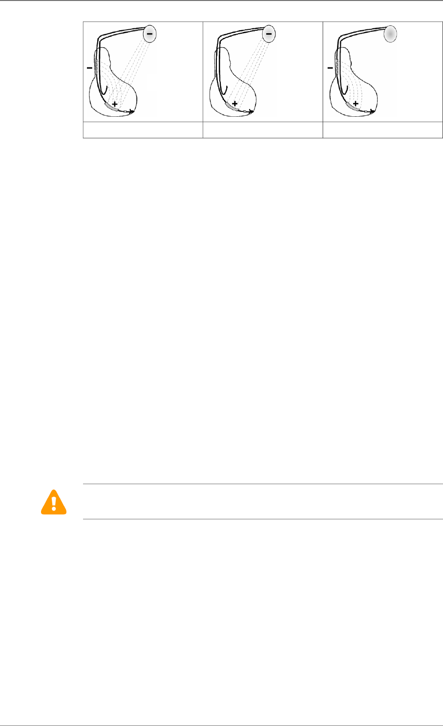
5. Use only the screwdriver provided with the defibrillator. Keep the screwdriver's shaft
perpendicular to the plane of the defibrillator (see figure below).
6. Removing the screwdriver: to avoid all risk of loosening screws during removal, hold the
screwdriver by its metal part and not by the handle.
WARNING: Ensure that the screwdriver's tip is fully inserted in the setscrew; otherwise the
screwdriver can damage the setscrew and prevent connection with or disconnection from the
lead.
To ensure full insertion, push the screwdriver's hex tip smoothly into the setscrew until it
reaches the bottom of the hex chamber in the screw, which can be felt as a solid metallic
contact. Do not implant the defibrillator if there is no feeling of solid metallic contact. Do not
implant the defibrillator if the wrench does not click when attempting to tighten the setscrew
on the lead pin.
NOTE: To optimize cardioversion/defibrillation shocks, electrodes must be positioned so that
the electric field between anode(s) and cathode covers the largest myocardial mass. In
normal conditions, the anode and cathode are adequately separated. In case of a short-
circuit, the shock may be aborted.
In the case of an external defibrillation shock delivered to the patient, always check the
programming and functioning of the device, in particular its capacity to deliver shocks.
14. IMPLANT PROCEDURE
SORIN – PLATINIUM 4LV SonR CRT-D 1844 – U906A 37

DEVICE IMPLANTATION
PLATINIUM 4LV SonR CRT-D 1844 should be implanted with the device identification
engraved side facing outwards for optimal communication with the programming head and
radiographic identification.
In order to prevent lead damage or dislodgement, it is important to loosely coil the leads and
place them in a manner that minimizes lead tension, twisting, sharp angles, and pressure.
The following factors should be considered in placing any excess of lead length:
1. recommendations/warnings of the (other) associated leads,
2. patient anatomy, and
3. pulse generator size and motion.
Suture the casing connector to the muscle using the hole provided for this purpose, in order
to avoid potential migration of the device into the pectoral muscle.
TESTS AND PROGRAMMING
During the implant testing procedure:
It is recommended that a safety margin of at least 10 J be demonstrated between the
effective shock energy and maximum programmable energy.
Enable shock therapies, then program the defibrillator.
Verify that the defibrillation shock impedance for each shock delivered is within the range of
30 to 150 ohms. Check the lead connection if the values are outside these boundaries.
Save the programming data on the programmer’s hard disk and on an external storage
device (if desired).
Resuscitation Availability:
Do not perform device testing unless an external defibrillator is available and medical
personnel skilled in cardiopulmonary resuscitation (CPR) are present.
Disable the ICD During Handling:
Program Shock Therapy to OFF during surgical implant and explant or post mortem
procedures. The device can deliver a serious high energy shock should accidental contact
be made with the defibrillation electrodes, the device can deliver a very high energy shock.
14.11.
14.12.
14. IMPLANT PROCEDURE
38 SORIN – PLATINIUM 4LV SonR CRT-D 1844 – U906A

15. SPECIAL MODES
SAFETY MODE (NOMINAL VALUES)
Nominal values may be rapidly restored by pressing the following button on the programming
head or programmer keyboard:
or via the Emergency button on the SMARTVIEW screen.
In safety mode, the defibrillator operates with the nominal parameters values in the table of
programmable parameters.
MAGNET MODE
When the magnet is applied:
― antiarrhythmia functions are inhibited (detection of rhythm disturbances, charging, and
therapy),
― hysteresis, VV delay and AVD paced/sensed offset are set to 0,
― pacing amplitude is set to 6 V,
― pulse width is set to maximum,
― the following functions are disabled: ventricular arrhythmia prevention, Mode Switch,
Anti-PMT, Smoothing, Rate Response.
When the magnet is removed:
― arrhythmia detection algorithms and sequential therapies are reinitialized,
― therapies start with the least aggressive program for each area.
The antiarrhythmia functions inhibition is extended after magnet removal if a charge occurred
just before the application of the magnet in order to ease the communication between the
device and the programmer.
The other parameters remain at their programmed value, including the ventricular paced
chamber parameter.
RESPONSE IN THE PRESENCE OF DISTURBANCE
If the defibrillator senses electrical noise at a frequency above 16 Hz, it switches to an
asynchronous mode at the basic rate. The programmed mode is restored as soon as the
noise is no longer detected.
Ventricular pacing may also be inhibited by ventricular noise. It can be restored by setting the
parameter “V pacing on noise” to “On”.
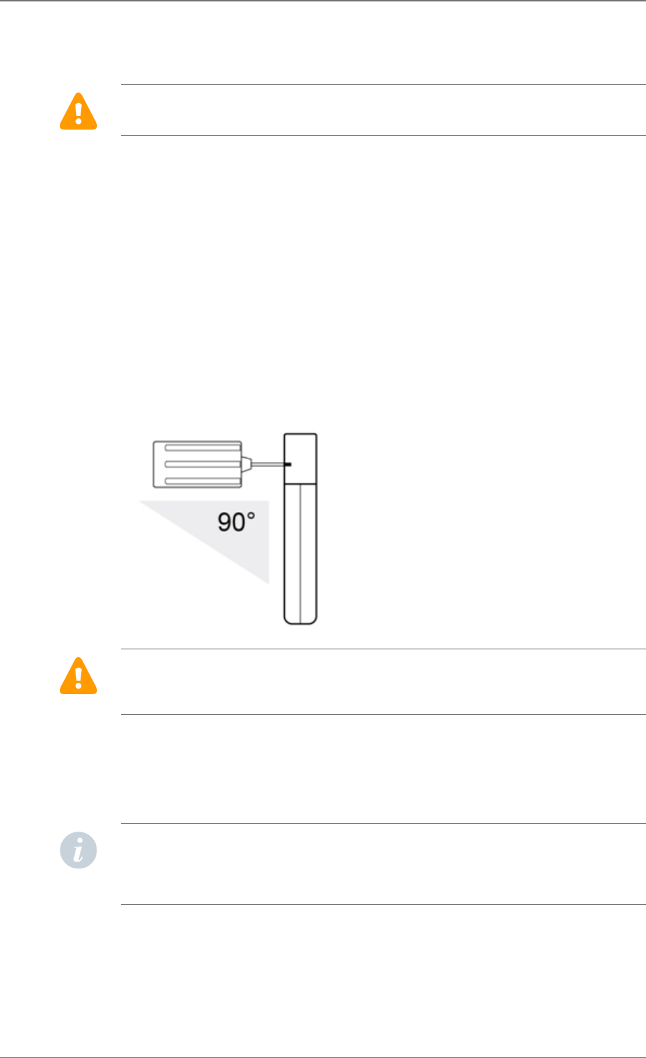
DETECTION CHARACTERISTICS IN THE PRESENCE OF
ELECTROMAGNETIC FIELDS
Per Clause 27.4 of Standard EN 45502-2-2, detection in the presence of electromagnetic
fields is characterized as follows:
― Differential mode:
15.1.
15.2.
15.3.
15.4.
15. SPECIAL MODES
SORIN – PLATINIUM 4LV SonR CRT-D 1844 – U906A 39
― Common mode rejection ratio:
16.6 Hz 50 Hz 60 Hz
Atrial channel ≥74 dB ≥74 dB ≥74 dB
Ventricular
channel
≥68 dB ≥68 dB ≥68 dB
For atrial sensitivity settings below 0.4mV, the ICD may detect noise lower than the level
specified in clause 27.5.1 of standard EN 45502-2-2 for frequencies below 200 Hz.
For ventricular sensitivity settings below 0.6mV, the ICD may detect noise lower than the level
specified in clause 27.5.1 of standard EN 45502-2-2 for frequencies below 200 Hz.
PROTECTION AGAINST SHORT-CIRCUITS
The defibrillator can undergo a short-circuit if the anode and cathode are not adequately
separated.
In this case, the shock is aborted and a warning will indicate that a short circuit (shock
impedance < 20 ohms) was detected during the last shock. The device may be damaged
compromising ability to provide shock therapy.
15.5.
15. SPECIAL MODES
40 SORIN – PLATINIUM 4LV SonR CRT-D 1844 – U906A

16. MAIN FUNCTIONS
AUTOMATIC LEAD MEASUREMENTS
Automatic pacing lead impedance measurement:
A lead impedance measurement is automatically performed on atrial and ventricular leads
every 6 hours. The daily mean impedance is stored for each chamber.
Automatic coil impedance measurement:
A coil impedance measurement is automatically performed on defibrillation coil(s) once per
day. The coil impedance is stored for each coil.
Automatic sensing measurement:
The amplitude of P and R waves are automatically measured at each cycle. Every 8.5
minutes, the amplitude of the last 8 P and R detections are averaged and stored.
ATRIAL TACHYARRHYTHMIA MANAGEMENT
Mode Switch:
This function is designed to limit the acceleration and variation of ventricular rate in the
presence of atrial arrhythmia.
VENTRICULAR TACHYARRHYTHMIA MANAGEMENT
Ventricular tachyarrhythmia prevention:
Set of algorithms that can be used to avoid the circumstances of ventricular tachyarrhythmia
onset.
Arrhythmia discrimination algorithm PARAD and PARAD+ (P And R based
Arrhythmia Detection):
PARAD is the algorithm used to discriminate sinus tachycardias (ST) and supraventricular
tachycardias (SVT) from ventricular tachycardias (VT).
PARAD+ is based on the PARAD algorithm but additionally takes into account the “AF
detect” discrimination criteria: the occurrence of a "long ventricular cycle" characteristic for
AF patients which is an additional arrhythmia classification criterion to improve identification
of atrial fibrillation and avoid inappropriate shocks.
Fast VT treatment:
Applies detection criteria on fast ventricular tachycardia that are different from those of the
VT zone, as well as different therapies. The fast VT zone is included in the VF zone: its
lower limit is determined by the programmed value for the VF zone and its upper limit by the
programmed value for the fast VT zone.
Polarity alternation on Max shock:
Reverses the programmed polarity of every second shock set at maximum energy. The
number, type, and energy of shocks is independently programmable by detection zone.
16.1.
16.2.
16.3.
16. MAIN FUNCTIONS
SORIN – PLATINIUM 4LV SonR CRT-D 1844 – U906A 41

Defibrillation threshold (DFT):
Be aware that the changes in the patient’s condition, drug regimen, and other factors
may change the defibrillation threshold (DFT) which may result in non-conversion of the
arrhythmia post-operatively. Successful conversion of ventricular fibrillation or ventricular
tachycardia during arrhythmia conversion testing is no assurance that conversion will occur
post-operatively.
PACING
BTO (Brady Tachy Overlap):
Enables cardiac resynchronization therapy within the slow VT zone to preserve patient
exercise capacity, without affecting detection or treatment of slow VTs.
Post-shock mode:
After any automatic shock therapy, the post-shock mode makes it possible to apply a pacing
mode other than the standard antibradycardia pacing mode and/or with different pacing
parameters.
SafeR (AAI <> DDD) mode:
Is intended to minimize deleterious effects of ventricular pacing. The defibrillator functions in
AAI mode, and temporarily switches to DDD mode upon the occurrence of AVB III, AVB II,
AVB I and ventricular pause.
Anti-PMT protection:
Is intended to protect the patient from Pacemaker-Mediated Tachycardia (PMT) without
reducing atrial sensing capability of the device.
SENSING
Automatic Refractory Periods:
Optimize sensing and make the implant programming easier. These periods are composed
of a minimal Refractory Period and a triggerable Refractory Period. The duration of the
refractory periods lengthens automatically as needed.
Committed period:
In DDI or DDD modes, the committed period is a non-programmable 95 ms ventricular
relative refractory period that starts with atrial pacing. If a ventricular event is sensed during
the committed period, but outside the blanking period, the ventricle is paced at the end of
the committed period. The committed period prevents inappropriate ventricular inhibition if
crosstalk occurs.
Protection against noise:
Allows the distinction between ventricular noise and ventricular fibrillation. If the device
senses ventricular noise, the ventricular sensitivity is decreased until noise is no longer
detected. Ventricular pacing can be inhibited to avoid a potential paced T-wave.
Automatic sensitivity control:
Optimizes arrhythmia detection and avoids late detection of T-waves and over-detection of
wide QRS waves. The device automatically adjusts the sensitivities based on the ventricular
sensing amplitude. In case of arrhythmia suspicion or after a paced event, the programmed
ventricular sensitivity will be applied. The minimum ventricular sensitivity threshold is 0.4 mV
(minimum programmable value).
16.4.
16.5.
16. MAIN FUNCTIONS
42 SORIN – PLATINIUM 4LV SonR CRT-D 1844 – U906A

SONR CRT OPTIMIZATION
SonR is a specific sensor, located at the tip of the atrial lead, that picks-up micro-accelerations
of the heart walls to derive information pertaining to cardiac contractility. The signal picked-
up by the SonR sensor can be processed by PLATINIUM 4LV SonR CRT-D 1844 in order
to automatically adjust VV delays and AV delays during rest and exercise for optimal
resynchronization therapy. In addition, the SonR signal is recorded during tachyarrhythmia
episodes to depict acute variations of cardiac contractility. PLATINIUM 4LV SonR CRT-D
1844 can also transmit real-time SonR signals via telemetry.
LV MULTIPOINT PACING (MP)
PLATINIUM 4LV SonR CRT-D 1844 features simultaneous multipoint left ventricular pacing
allowing LV pacing on 2 differents vectors at the same time, named MP1 and MP2 LV pacing
sites.
FOLLOW-UP FUNCTION
Storage of memory data:
AIDA (Automatic Interpretation for Diagnosis Assistance) software provides access up to 6
months of patient follow-up with day by day data collection, or up to 24 hours with hourly data
collection. Episodes of ventricular tachyarrhythmia are recorded with one programmable
EGM channel which can be selected, in addition to RV EGM.
Alerts / Warnings:
The device routinely performs security self-checks and technical measurements to ensure
system integrity. When system integrity is found to be at risk outside a follow-up, alerts are
stored in the device memory. When system integrity is found to be at risk during a follow-
up, the information is managed by a warning (pop-up message) to immediately notify the
user. For example, the following types of events can trigger a warning or an alert: technical
problem during a shock, lead impedance or shock continuity measurements out-of-range,
battery depletion, …
REMOTE MONITORING FUNCTION
Remote monitoring enables the automatic remote transmission of implant data to the
physician thanks to the wireless Radio Frequency (RF) communication ability of the implant in
order to provide a comprehensive report to the physician about device functioning and patient
cardiac status without having the patient physically in the clinic.
The data is transmitted from the implant to the SMARTVIEW monitor, a small transmitter
placed in the patient's home.
Implant data are first transmitted to the SMARTVIEW monitor via RF. Data are then routed
through the phone line or via GPRS to an internet website. This website is responsible for
transforming the implant data into a comprehensive report that can be consulted by the
physician.
SMARTVIEW Monitor
The SMARTVIEW monitor is a small device equipped with an RF transmission module to
communicate with the implant and a modem to export data through the internet.
The SMARTVIEW monitor is delivered to the patient who has to install it at home. Preferably
the SMARTVIEW monitor will be placed on the nightstand of the patient, as close as possible
to the side of the bed where the patient usually sleeps. The SMARTVIEW monitor connects
to the phone line of the patient and the power plug. Regular transmissions are done during
16.6.
16.7.
16.8.
16.9.
16.9.1.
16. MAIN FUNCTIONS
SORIN – PLATINIUM 4LV SonR CRT-D 1844 – U906A 43

the night when the patient is asleep next to the SMARTVIEW monitor without any intervention
from the patient.
Transmission trigger
There are 3 different triggers for a remote transmission:
― the remote follow-up transmission is scheduled by the physician to occur regularly
(according to the programming).
― the alert transmission will take place when the implant has recorded an abnormal
events. The list of abnormal event is available in a following paragraph. Alert conditions
are checked daily.
― the on-demand follow-up transmission is triggered by the patient himself through the
use of a specific button on the SMARTVIEW monitor.
Data transmitted
The data transmitted are identical to the data available during a standard interrogation with
the dedicated programmer. All counters, histograms, IEGMs and diagnosis available in the
device are transmitted containing (not an exhaustive list):
― programmed parameters
― information on patient and system implanted
― battery status
― lead status (brady leads and defibrillation coils)
― pacing counters and mean heart rate (brady)
― atrial and ventricular arrhythmia counters and episodes
― ventricular therapy counters
Data are presented in the form of 2 reports to the physician: the first one contains a summary
of major counters, histograms, warnings and diagnosis. The second one presents the most
important IEGM episodes automatically selected based on the degree of severity for the
patient.
User website
On the website, the physician is able to:
― consult and schedule the remote follow-ups of their patient
― configure additional ways of being notified of alerts (for instance by SMS, fax or e-mail)
― consult, print and export patient reports
Alert system
The following set of alert triggers can be independently programmed ON/OFF by the
physician using the dedicated programmer and can trigger an alert transmission:
― Low or high lead impedance (A, RV, LV) (if MP is ON, both MP1 and MP2 can trig the
alert)
― Abnormal coil impedance (shock lead)
― Low or high shock impedance
― Inefficient high energy shock
16.9.2.
16.9.3.
16.9.4.
16.9.5.
16. MAIN FUNCTIONS
44 SORIN – PLATINIUM 4LV SonR CRT-D 1844 – U906A

― All shocks programmed OFF
― Shock treated VT/VF
― ATP treated VT/VF
― Lack of V pacing in CRT device
― Suspicion of noise on the V lead
― AT/AF occurrence
― Fast V rate during AT/AF
The following set of alert triggers (system alerts) cannot be deactivated when the Alerts are
programmed “On” and can trigger an alert transmission:
― Battery depletion – RRT
― Device reset
― Excessive charge time (>25s)
― System integrity
WARNING: The use of remote monitoring does not replace regular follow-up. Therefore,
when using remote monitoring, the time period between follow-ups visits may not be
extended.
16. MAIN FUNCTIONS
SORIN – PLATINIUM 4LV SonR CRT-D 1844 – U906A 45

17. PATIENT FOLLOW-UP
FOLLOW-UP RECOMMENDATIONS
Before the patient is discharged and at each subsequent follow-up visit, it is advisable to:
― check the occurrence of system warnings
― check the battery status,
NOTES:
If the last reforming, charge or shock occurred during the week preceding the interrogation,
the last battery value may be still impacted by the event. One week post event, the battery
will recover its steady state value.
Automatic capacitor charging may affect communication between the device and the
programmer.
― check the integrity of the pacing and defibrillation leads,
― check for proper sensing (sensitivity, crosstalk) and pacing ; set the pacing amplitude to
twice the pacing threshold,
― interrogate the implant memories (AIDA),
― check the efficacy of the therapies delivered,
― keep a printout of programmed parameters, test results, and memory data,
― reset the memory data and statistics.
These operations should be performed by medical personnel in an appropriate care unit, with
resuscitation equipment present.
It is recommended that a routine follow-up examination be done one month after discharge,
and then every three months until the device nears the replacement date.
Refer to the online help for a description of displayed warnings, and the necessity to contact
Sorin for an evaluation.
Implant software upgrade:
In case a new implant software is downloaded in the device memory through the
programmer, a warning message could be displayed by the programmer to inform the user
and give the correct instructions to follow.
HOLTER FUNCTION
The Holter records markers and EGM on RV and on 1 programmable channel: A / RAring –
CAN / RVcoil – CAN / RVtip – CAN / RVring – CAN/ RVcoil – SVC / SVC – CAN / LVtip1 -
LV2 / LVtip1 - RVring / LVtip1 – LV4 / LVtip1 – CAN / LV2 - CAN / LV3 – LV2 / LV3- RVring /
LV3 - LV4 / LV3 – CAN / LV2-LV4 / LV4 - CAN:
― Up to 10 episodes and 5 min EGM on significant events: AV block switch, lead
impedance out of range.
― Up to 16 tachyarrhythmia episodes as well as the therapy history.
17.1.
17.2.
17. PATIENT FOLLOW-UP
46 SORIN – PLATINIUM 4LV SonR CRT-D 1844 – U906A
Stored Tachyarrythmia Episodes:
PLATINIUM 4LV SonR CRT-D 1844 stores up to 16 episodes (VF, VT, Slow VT, SVT/ST, non-
sustained) with a total of 25.6 min of high resolution EGM and 5 min of SonR signal.
For each episode four levels of details are presented:
― Tachogram (to visualize RR, PP, PR and RP intervals)
― Event log for the entire episode:
― PARAD/PARAD+ analysis for each majority,
― Delivered therapies,
― Markers: Atrial, ventricular and biventricular markers, sensed, paced and in relative
refractory periods,
― EGM: onset and detection of the arrhythmia, on two therapies, and the return to slow
rhythm by recording electrogram.
Therapy history
For each arrhythmia detection, each therapy delivered (either automatically or during an
electrophysiological study) and at the end of each arrhythmia, PLATINIUM 4LV SonR CRT-D
1844 records the type of majority rhythm, the number of ATP sequences delivered, the energy
and the number of shocks delivered.
RECOMMENDED REPLACEMENT TIME (RRT)
Recommended Replacement Time (RRT)(1) is controlled by: battery voltage equal to 2.62 V ±
0.01 V
CAUTION: The defibrillator should be replaced as soon as the Recommended Replacement
Time (RRT) point is reached.
Between the RRT and the EOS (End of Service)(2), PLATINIUM 4LV SonR CRT-D 1844 can
still function for:
― 10.8 months (100% atrial and biventricular pacing in DDD mode, 500 ohms, with as-
shipped settings), and deliver 11 shocks at 34 J or
― 10,4 months (0% pacing, sensors OFF) and deliver 21 shocks at 34 J.
Once the Recommended Replacement Time (RRT) point has been reached, the device
operates normally, except that the charge time increases. Under normal conditions (and
without programmer use) the charge times are as follows:
Shock energy Charge time (sec)
BOS(3) 42 J 10 (± 2)
RRT 42 J 13 (± 3)
(1) Recommended Replacement Time (RRT) corresponds to Elective Replacement Indicators
(ERI) previously used.
(2) End of Service (EOS) corresponds to End of Life (EOL) previously used.
(3) Beginning of Service (BOS) corresponds to Beginning of Life (BOL) previously used.
EXPLANTATION
The defibrillator should be explanted in the following cases:
17.3.
17.4.
17. PATIENT FOLLOW-UP
SORIN – PLATINIUM 4LV SonR CRT-D 1844 – U906A 47

― The Recommended Replacement Time (RRT) point is reached
― Confirmed malfunction
― Burial of the patient (for environmental reasons, the local regulation may require the
explantation of the devices containing a battery supply)
― Cremation of the patient (the defibrillator may explode if placed in an incinerator)
The explanted defibrillator should not be reused in another patient.
All explanted defibrillators should be returned to Sorin, carefully cleaned of all traces of
contamination. Cleaning may be done by immersing them in an aqueous sodium hypochlorite
containing at least 1% chlorine, followed by rinsing copiously with water.
The defibrillator should be protected against mechanical impact and the temperature
variations that may occur during shipping.
Before explantation, it is advisable to:
― Print out all programmed parameters, statistics and Holter function report,
― Save Patient data on floppy disk or hard disk,
― Disable shock therapies (VT and VF) to avoid any risk of untimely shock.
DEFIBRILLATOR IDENTIFICATION
The defibrillator can be interrogated and programmed via telemetry, using the programming
head interfaced with the Sorin dedicated programmer.
Position the programming head over the telemetry antenna located in the upper part of the
device, in order to communicate effectively via telemetry (see diagram below).
The device can be non-invasively identified as follows:
1. Take an x-ray to identify the name of the manufacturer and model, printed on the device
(X-ray ID is SEA for PLATINIUM range).
2. Interrogate the device using the Sorin dedicated programmer. The model and serial
number of the device are automatically displayed. The first figure in the serial number
corresponds to the last figure in the year of manufacture.
17.5.
17. PATIENT FOLLOW-UP
48 SORIN – PLATINIUM 4LV SonR CRT-D 1844 – U906A
18. SUPPLEMENTAL INFORMATION
Clinical data presented in this section are from the SafeR (AAI <> DDD) clinical study. SafeR
(AAI <> DDD) operation in PLATINIUM is similar to that in the Symphony pacemaker. The
data provided are applicable to PLATINIUM 4LV SonR CRT-D 1844.
ADVERSE EVENTS IN THE SAFER (AAI <> DDD) STUDY
Clinical study of the SafeR (AAI <> DDD) included 45 Symphony 2550 devices implanted in
45 patients. No serious adverse events were device- or feature-related. There were no deaths
in the study.
Table 1: Summary of Symphony safety data during study
Patients Number of events
Number
of pa-
tients
% of
patients
Number
of
events
Events per
device year
(a)
Deaths 0 0 0 0
Explants 0 0 0 0
Serious pacemaker related events outside
the use of SafeR (AAI <> DDD)
0 0 0 0
Non-serious pacemaker related events out-
side the use of SafeR (AAI <> DDD)
0 0 0 0
Serious events due to the use of SafeR
(AAI <> DDD)
0 0 0 0
Non-serious events related due to the use
SafeR (AAI <> DDD)
13 28.9 15 3.2
Serious non-pacemaker related events 6 13.3 9 1.9
Non-serious non-pacemaker related events 8 17.8 8 1.7
(a) 4.74 device years
Non-serious events due to the use of SafeR 2 (AAI <> DDD) included: delay in switching on
2nd degree AV block, inappropriate classification of a PAC, disagreement between markers
and recorded EGM, atrial pacing above the maximum rate, recycling on an R-wave in
a refractory period, and disagreement in the statistics for switches to DDD. No patient
symptoms were associated with these events.
SAFER (AAI <> DDD) CLINICAL STUDY
SafeR (AAI <> DDD) mode in PLATINIUM is similar to that in Symphony.
The differences in SafeR (AAI <> DDD) mode between the two devices are:
― To prevent long RR intervals during VT/VF, SafeR (AAI <> DDD) has no effect during
VT/VF therapy, electrophysiologic studies, and post-shock recovery.
― The maximum acceptable AV delay for first degree AV block varies as a function of
pacing rate.
― PLATINIUM requires a ventricular sensed event to atrial paced event (RA) interval of at
least 100 ms. Therefore, the device lengthens the atrial escape interval so that it ends at
least 102 ms after the ventricular event.
18.1.
18.2.
18. SUPPLEMENTAL INFORMATION
SORIN – PLATINIUM 4LV SonR CRT-D 1844 – U906A 49
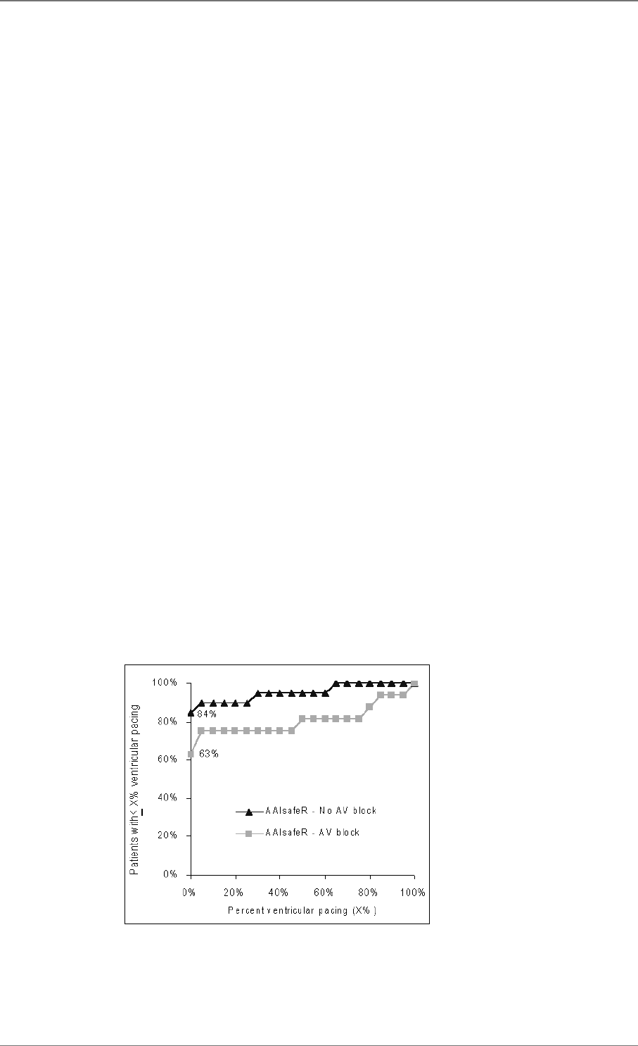
― During atrial fibrillation episode, pause criterion is fixed to 2s to avoid long bradycardia
episodes in switching to DDD mode.
Despite these differences, the data collected on Symphony devices are applicable to
PLATINIUM because the principles of SafeR (AAI <> DDD) operation did not change. The
criteria for switching from AAI to DDD (or vice versa) did not change. The device’s method for
evaluating the presence of AV conduction did not change.
Methods:
All patients were implanted with a Symphony Model 2550 dual-chamber rate-responsive
pacemaker with SafeR (AAI <> DDD) mode. A variety of marketed atrial and ventricular
pacing leads were used. The pacemaker was programmed and interrogated via bi-directional
telemetry using a Sorin dedicated programmer and a CPR3 programming head.
The study’s routine evaluation consisted of enrollment, pre-discharge evaluation, and a
scheduled follow-up visit at one month. At pre-discharge, a 24-hour Holter recording was
performed and pacemaker memory was read. At one month, pacemaker memory was read.
Investigators also documented adverse events.
Patients studied:
A total of 45 patients from 12 centers had Symphony 2550 pacemakers with SafeR (AAI <>
DDD). Of these, 14 (31 %) were female and 31 (69 %) were male. Mean patient age (± SD)
was 74 ± 9 years.
Primary indications for implant were: 1st degree AV block (11.1 %), 2nd degree AV block (6.7
%), 3rd degree AV block (22.2 %), sinus node dysfunction (62.2 %) or other (6.7 %).
Effectiveness results:
To determine the effectiveness of SafeR (AAI <> DDD) mode, the percentage of ventricular
pacing provided over one month was recorded from pacemaker memory.
Thirty-five patients contributed data to evaluate the percentage of ventricular pacing provided
with SafeR (AAI <> DDD). Twenty-nine patients had 1 % or less ventricular pacing and six
patients had a range of 28-97 % ventricular pacing. The graph below shows the distribution
of ventricular pacing observed in patients with and without AV block as a primary indication
for implant.
The graph shows that many patients programmed to SafeR (AAI <> DDD) had less than 1%
ventricular pacing:
18. SUPPLEMENTAL INFORMATION
50 SORIN – PLATINIUM 4LV SonR CRT-D 1844 – U906A

― 84 % of patients without AV block at implant.
― 63 % of patients with AV block at implant.
In a representative reference group(1) of patients programmed to DDD, none had less than 1
% ventricular pacing and only 10 % had less than 90 % ventricular pacing regardless of AV
block indication at implant.
The actual reduction of ventricular pacing that SafeR (AAI <> DDD) provides in an individual
will depend on the amount of time that the patient spends in AV block. SafeR (AAI <> DDD)
cannot and should not provide any decrease in ventricular pacing while the patient is in AV
block.
(1) Pioger G, Jauvert G, Nitzsché R, Pozzan J, Laure H, Zigelman M, Leny G, Vandrell M,
Ritter P, and Cazeau S. Incidence and predictive factors of atrial fibrillation in paced patients.
PACE, 28, Supp 1: S137-141; January 2005. This was a prospective observational study of
377 patients with a functionally similar device programmed to DDD. The primary indications
for implant were: AV block (49 %), sinus node disease (16 %), brady-tachy syndrome (5 %),
AV block + sinus node disease (19 %), AV block + brady-tachy syndrome (6 %), and brady-
tachy syndrome + sinus node disease (5 %).
18. SUPPLEMENTAL INFORMATION
SORIN – PLATINIUM 4LV SonR CRT-D 1844 – U906A 51

19. PHYSICAL CHARACTERISTICS
Dimensions 78.1 x 54.3 x 11.1 mm
Weight 91 g
Volume 33.7 cm3
Active surface area
of casing
62.4cm2
Connector Atrium: SonR (IS-1 bipolar compatible). Right ventricle: DF4. Left ventricle:
IS4.
MATERIALS USED
Active surface area
of casing
99% pure titanium
Connectors Polyurethane* and silicone elastomer*
*Medical-grade materials that have undergone "in vitro" and "in vivo" qualifications.
19.1.
19. PHYSICAL CHARACTERISTICS
52 SORIN – PLATINIUM 4LV SonR CRT-D 1844 – U906A
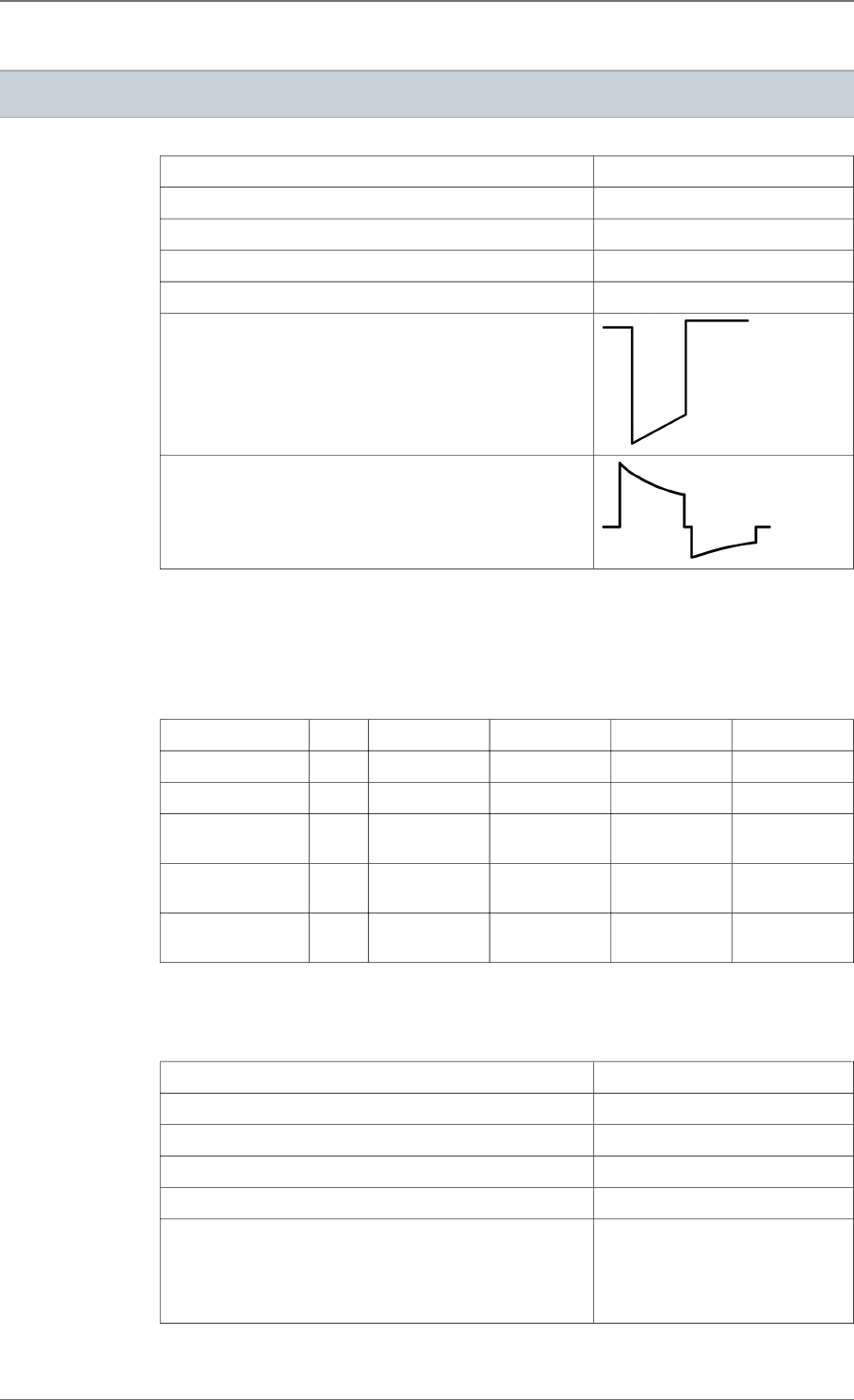
20. ELECTRICAL CHARACTERISTICS
Atrial input impedance 80 kilohms ± 30 %
Ventricular input impedance 80 kilohms ± 30 %
D.C. capacitance 149 µF ± 8 %
Capacitor reformation No reformation required
Rate limit 192 ppm ± 10 ppm
Pacing waveform
Defibrillation waveform
TABLE OF DELIVERED SHOCK ENERGY AND VOLTAGE
The relationship between stored energies, maximum voltages and delivered energies (at 37
°C, 50 ohm load) for the minimum, low, mean and maximum programmed energy values is
as follows:
Stored energy (J) 0.5 10 20 34 42
V1 (Volt) 71 332 471 617 686
V2 (Volt) 35 167 235 309 342
Delivered E:
Phase 1 (J)
0.32 6.94 14.0 23.8 29.6
Delivered E:
Phase 2 (J)
0.08 1.75 3.4 6.0 7.4
Delivered E: Total
(J)
0.4 8.7 17.4 30 37
Tolerances are 12% for voltage (25% at 0.5 J) and 30% for energy.
BATTERY
Manufacturer Greatbatch
Type Quasar High Rate (QHR)
Model GB 3070
Number of batteries 1
Total capacity 2192 mAh
Usable capacity Between BOS and RRT:
1530 mAh.
Between BOS and EOS:
1910 mAh.
20.1.
20.2.
20. ELECTRICAL CHARACTERISTICS
SORIN – PLATINIUM 4LV SonR CRT-D 1844 – U906A 53

Voltage BOS: 3.24 V. RRT: 2.62 V. EOS:
2.5 V.
LONGEVITY
The longevities are calculated by taking into account 6 months storage with the following
conditions:
― Mode: DDD
― Basic rate: 60 ppm
― Pulse width (A, RV, LV): 0.35 ms
― EGM:ON
― SonR: ON
― MP: OFF
― 2 battery reformings per year (at 34J), replaced by shocks if any
― Remote monitoring: ON, daily check, 4 follow-ups and 5 full alert reports per year
― RF telemetry: ON, 120min at implantation + 15min at discharge + 15min for in-clinic
quarterly follow-ups
Longevity projection at 500 Ω pacing impedance:
A pacing (%) 100 100 1 15 1 30 0
BiV pacing (%) 100 100 100 100 100 100 0
A, RV Pacing amplitude (V) 3.5 3.5 3.5 4.5 2.5 2.5 -
LV Pacing amplitude (V) 3.5 3.5 3.5 4.5 2.5 3.0 -
Sensor OFF ON ON ON OFF OFF OFF
Max shocks (42J) per year 4 4 4 4 0 3 4
Longevity (years) 6.8 6.7 7.8 6.3 11.1 9.6 12.2
Longevity projection at 600 Ω pacing impedance:
A pacing (%) 100 100 1 15 1 30 0
BiV pacing (%) 100 100 100 100 100 100 0
A, RV Pacing amplitude (V) 3.5 3.5 3.5 4.5 2.5 2.5 -
LV Pacing amplitude (V) 3.5 3.5 3.5 4.5 2.5 3.0 -
Sensor OFF ON ON ON OFF OFF OFF
Max shocks (42J) per year 4 4 4 4 0 3 4
Longevity (years) 7.3 7.1 8.2 6.7 11.6 10.0 12.2
Longevity projection at 700 Ω pacing impedance:
A pacing (%) 100 100 1 15 1 30 0
BiV pacing (%) 100 100 100 100 100 100 0
A, RV Pacing amplitude (V) 3.5 3.5 3.5 4.5 2.5 2.5 -
LV Pacing amplitude (V) 3.5 3.5 3.5 4.5 2.5 3.0 -
Sensor OFF ON ON ON OFF OFF OFF
Max shocks (42J) per year 4 4 4 4 0 3 4
Longevity (years) 7.6 7.5 8.5 7.1 11.9 10.3 12.2
20.3.
20. ELECTRICAL CHARACTERISTICS
54 SORIN – PLATINIUM 4LV SonR CRT-D 1844 – U906A
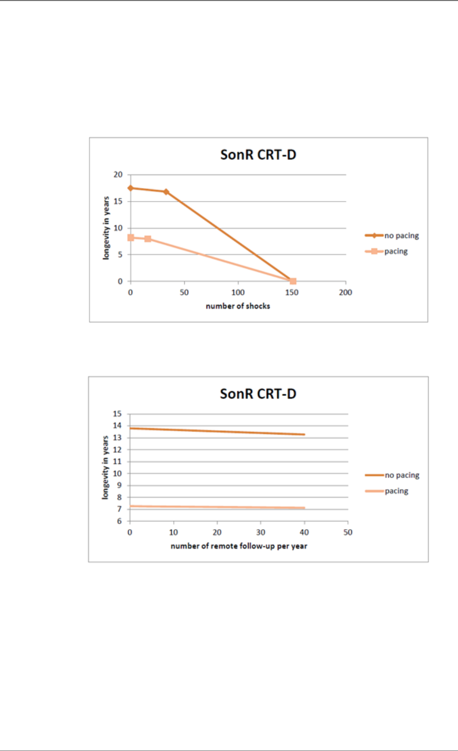
If Multipoint LV Pacing (MP) is set to ON, an additional LV pacing vector is activated.
Consequently, the device longevity is reduced from 0.8 to 1.6 year dependent on the device
operating under the conditions described in the tables above, with MP activated for the
entire lifetime of the device from implant to explant, with the same LV pacing parameters (LV
amplitude, LV pulse width) and impedance applied on both LV vectors (MP1 and MP2).
1h of additional RF programming session reduces the device longevity from 1 to 2 weeks
depending on the device functioning mode (no pacing, 100% pacing). The mean longevity as
a function of shocks delivered at maximum energy, with and without pacing, is as follows:
The mean longevity as a function of yearly remote follow-ups1, with and without pacing, is as
follows:
1. An excessive number of remote follow-ups can have a non-negligible impact on device
longevity.
20. ELECTRICAL CHARACTERISTICS
SORIN – PLATINIUM 4LV SonR CRT-D 1844 – U906A 55
21. PROGRAMMABLE PARAMETERS
Measured at 37 °C under a 500 ohm load.
ANTIBRADYCARDIA PACING
Basic parameters Values Nominal value "As shipped"
value
Mode VVI-VVIR-DDD-DDDR-DDD/DDIR-DDI-
DDIR-SafeR (AAI <=> DDD)-
SafeR-R (AAIR <=> DDDR)-DOO-VOO-
OOO
VVI DDD
Basic rate (ppm) (1) From 30 to 90 by steps of 5 (± 4 %) 60 60
Maximum rate (ppm) From 100 to 145 by steps of 5 (± 6 %) 120 120
Rate hysteresis (%) 0-5-10-20-35 (± 18 ms) 0 0
Rest AV delay (ms) 30-40-45-55-65-70-80-85-95-100-110-
115-125-135-140-150-155-165-170-180-
190-195-205-210-220-225-235-250
(± 19 ms)
125 125
Exercise AV delay
(ms)
30-40-45-55-65-70-80-85-95-100-110-
115-125-135-140-150-155-165-170-180-
190-195-205-210-220-225-235-250
(± 19 ms)
80 80
AVD Paced/Sensed
Offset (ms)
0-10-15-25-30-40-45-55-65-70-80-85-95
-100-110-115-125 (± 1 ms)
65 65
(1) The corresponding periods are (in ms):
2000-1714-1500-1333-1200-1091-1000-923-857-800-750-706-667 ms.
Special features Values Nominal value "As shipped"
value
Rate smoothing OFF-Very slow-Slow-Medium-Fast OFF OFF
Mode Switch ON-OFF ON ON
Physical activity Very low-Low-Medium-High-Very high Medium Medium
Exercise AV opt. rate
(ppm)
From 70 to 120 by steps of 5 90 90
CRT optimization OFF-Monitor-AV-AV+VV OFF OFF
21.1.
21. PROGRAMMABLE PARAMETERS
56 SORIN – PLATINIUM 4LV SonR CRT-D 1844 – U906A
Pacing/Sensing Values Nominal value "As shipped"
value
Atrial sensitivity (mV)
(1) From 0.2 to 4 by steps of 0.2 (± 50 %) 0.4 0.4
Atrial amplitude (V)
(2) 1-1.5-2-2.5-3-3.5-4-4.5-5-6 (± 20 %) 5 3.5
Atrial pulse width
(ms)
0.12-0.25-0.35-0.5-0.6-0.75-0.85-1
(± 10 %)
0.35 0.35
Ventricular sensitivity
(mV) (1) From 0.4 to 4 by steps of 0.2 (± 50 %) 0.4 0.4
RV amplitude (V) (2) 1-1.5-2-2.5-3-3.5-4-4.5-5-6 (± 20 %) 5 3.5
RV pulse width (ms) 0.12-0.25-0.35-0.5-0.6-0.75-0.85-1
(± 10 %)
0.35 0.35
LV amplitude (V) (2) 0.1-0.25-0.35 (± 80 %)
0.5-0.6-0.75-0.85 (± 30 %)
1-1.1-1.25-1.35-1.5-1.6-1.75-1.85-2-2.1-
2.25-2.35-2.5-2.6-2.75-2.85-3-3.1-3.25-
3.35-3.5-3.6-3.75-3.85-4-4.1-4.25-4.35-
4.5-4.6-4.75-4.85-5-5.1-5.25-5.35-5.5-
5.6-5.75-5.85-6-6.1-6.25-6.35-6.5-6.6-
6.75-6.85-7 (± 20 %)
5 3.5
LV pulse width (ms) 0.12-0.25-0.35-0.5-0.6-0.75-0.85-1-1.1-
1.25-1.35-1.5-1.6-1.75-1.85-2 (± 10 %)
0.35 0.35
LV pacing polarity [LV tip1-CAN]-[LV tip1-LV2]-
[LV tip1-RV ring]-[LV tip1-RV coil]-
[LV tip1-LV4]-[LV2-CAN]-[LV2- RV coil]-
[LV2 -LV4]-[LV3-CAN]-[LV3-LV4]-
[LV3-LV2]-[LV3-RV ring]-[LV3-RVcoil]-
[LV4-RV coil]
[LV tip1-LV2] [LV tip1-LV2]
Multipoint LV Pacing
(MP)
ON-OFF OFF OFF
V chambers Right-R+L-L+R R+L R+L
VV delay (ms) 0-16-24-32-40-48-56-64 (± 3 ms) 0 0
(1) Values are measured using a positive and negative triangular signal of 2/13 ms.
(2) The correlation between the programmed amplitudes, the stored amplitudes and the mid-pulse
delivered amplitudes under a 500 ohm load are given in the following table:
Programmed
amplitude
(V)
Stored
amplitude
(V)
Mid-pulse
delivered
amplitude
(V)
0.10* 0.20 0.19
0.25* 0.26 0.22
0.35* 0.39 0.33
0.50* 0.52 0.44
0.60* 0.72 0.61
0.75* 0.85 0.72
0.85* 0.98 0.83
1.00 1.11 0.94
Programmed
amplitude
(V)
Stored
amplitude
(V)
Mid-pulse
delivered
amplitude
(V)
1.10* 1.24 1.05
1.25* 1.37 1.16
1.35* 1.50 1.27
1.50 1.63 1.38
1.60* 1.76 1.49
1.75* 1.89 1.60
1.85* 2.02 1.71
2.00 2.10 1.78
21. PROGRAMMABLE PARAMETERS
SORIN – PLATINIUM 4LV SonR CRT-D 1844 – U906A 57
Programmed
amplitude
(V)
Stored
amplitude
(V)
Mid-pulse
delivered
amplitude
(V)
2.10* 2.21 1.87
2.25* 2.34 1.98
2.35* 2.47 2.09
2.50 2.60 2.20
2.60* 2.73 2.31
2.75* 2.87 2.42
2.85* 3.00 2.53
3.00 3.15 2.67
3.10* 3.26 2.76
3.25* 3.39 2.87
3.35* 3.52 2.98
3.50 3.65 3.09
3.60* 3.78 3.20
3.75* 3.91 3.31
3.85* 4,04 3.42
4.00 4.20 3.55
4.10* 4.30 3.64
4.25* 4.43 3.75
4.35* 4.56 3.86
4.50 4.69 3.97
Programmed
amplitude
(V)
Stored
amplitude
(V)
Mid-pulse
delivered
amplitude
(V)
4.60* 4.82 4.08
4.75* 4.95 4.19
4.85* 5.08 4.30
5.00 5.25 4.44
5.10* 5.34 4.52
5.25* 5.47 4.63
5.35* 5.60 4.74
5.50* 5.73 4.85
5.60* 5.86 4.96
5.75* 5.99 5.07
5.85* 6.12 5.18
6.00 6.30 5.33
6.10* 6.38 5.40
6.25* 6.51 5.51
6.35* 6.64 5.62
6.50* 6.77 5.73
6.60* 6.90 5.84
6.75* 7.03 5.95
6.85* 7.16 6.06
7.00* 7.35 6.22
* For left ventricular amplitude only.
If Multipoint LV Pacing (MP) is set to ON, LV pacing parameters (LV amplitude, LV pulse width
and LV pacing polarity) are replaced by the following parameters:
21. PROGRAMMABLE PARAMETERS
58 SORIN – PLATINIUM 4LV SonR CRT-D 1844 – U906A

Pacing/Sensing Values Nominal value "As shipped"
value
LV amplitude – MP1
(V) (1) 0.1-0.25-0.35 (± 80 %)
0.5-0.6-0.75-0.85 (± 30 %)
1-1.1-1.25-1.35-1.5-1.6-1.75-1.85-2-2.1-
2.25-2.35-2.5-2.6-2.75-2.85-3-3.1-3.25-
3.35-3.5-3.6-3.75-3.85-4-4.1-4.25-4.35-
4.5-4.6-4.75-4.85-5-5.1-5.25-5.35-5.5-
5.6-5.75-5.85-6-6.1-6.25-6.35-6.5-6.6-
6.75-6.85-7- (± 20 %)
5 3.5
LV pulse width –
MP1 (ms)
0.12-0.25-0.35-0.5-0.6-0.75-0.85-1-1.1-
1.25-1.35-1.5-1.6-1.75-1.85-2 (± 10 %)
0.35 0.35
LV pacing polarity –
MP1
[LV tip1-CAN]-[LV tip1-LV2]-
[LV tip1-RV ring]-[LV tip1-RV coil]-
[LV tip1-LV4]-[LV2-CAN]-[LV2- RV coil]-
[LV2 -LV4]
[LV tip1-LV2] [LV tip1-LV2]
LV amplitude – MP2
(V) (1) 0.1-0.25-0.35 (± 80 %)
0.5-0.6-0.75-0.85 (± 30 %)
1-1.1-1.25-1.35-1.5-1.6-1.75-1.85-2-2.1-
2.25-2.35-2.5-2.6-2.75-2.85-3-3.1-3.25-
3.35-3.5-3.6-3.75-3.85-4-4.1-4.25-4.35-
4.5-4.6-4.75-4.85-5-5.1-5.25-5.35-5.5-
5.6-5.75-5.85-6-6.1-6.25-6.35-6.5-6.6-
6.75-6.85-7- (± 20 %)
5 3.5
LV amplitude – MP2
(ms)
0.12-0.25-0.35-0.5-0.6-0.75-0.85-1-1.1-
1.25-1.35-1.5-1.6-1.75-1.85-2 (± 10 %)
0.35 0.35
LV pacing polarity –
MP2
[LV3-CAN]-[LV3-LV4]-[LV3-LV2]-
[LV3-RV ring]-[LV3-RVcoil]-[LV4-RV coil]
[LV3-LV4] [LV3-LV4]
(1) The correlation between the programmed amplitudes, the stored amplitudes and the mid-pulse
delivered amplitudes under a 500 ohm load are given in the table above.
Ventricular arrhyth-
mia algorithms
Values Nominal value "As shipped"
value
Atrial pacing on PVC Yes-No No No
Post extrasystolic
pause suppression
Yes-No No No
Acceleration on PVC Yes-No No No
Max acceleration
rate (ppm)
From 60 to 145 by steps of 5 100 100
21. PROGRAMMABLE PARAMETERS
SORIN – PLATINIUM 4LV SonR CRT-D 1844 – U906A 59

Post-shock mode Values Nominal value "As shipped"
value
Mode OFF-VVI-DDI-DDD OFF OFF
Duration 10s-20s-30s-1min-2min-3min-4min-5min 20s 20s
Basic rate (ppm) From 50 to 90 by steps of 5 (± 4 %) 60 60
Rest AV delay (ms) 30-40-45-55-65-70-80-85-95-100-110-
115-125-135-140-150-155-165-170-180-
190-195-205-210-220-225-235-250
(± 19 ms)
125 125
Exercise AV delay
(ms)
30-40-45-55-65-70-80-85-95-100-110-
115-125-135-140-150-155-165-170-180-
190-195-205-210-220-225-235-250
(± 19 ms)
80 80
AVD Paced/Sensed
Offset (ms)
0-10-15-25-30-40-45-55-65-70-80-85-95
-100-110-115-125 (± 1 ms)
65 65
A amplitude (V) 1-1.5-2-2.5-3-3.5-4-4.5-5-6 (± 20 %) 5 3.5
A pulse width (ms) 0.12-0.25-0.35-0.5-0.6-0.75-0.85-1
(± 10 %)
0.35 0.35
RV amplitude (V) 1-1.5-2-2.5-3-3.5-4-4.5-5-6 (± 20 %) 5 3.5
RV pulse width (ms) 0.12-0.25-0.35-0.5-0.6-0.75-0.85-1
(± 10 %)
0.35 0.35
LV amplitude (V) 0.1-0.25-0.35 (± 80 %)
0.5-0.6-0.75-0.85 (± 30 %)
1-1.1-1.25-1.35-1.5-1.6-1.75-1.85-2-2.1-
2.25-2.35-2.5-2.6-2.75-2.85-3-3.1-3.25-
3.35-3.5-3.6-3.75-3.85-4-4.1-4.25-4.35-
4.5-4.6-4.75-4.85-5-5.1-5.25-5.35-5.5-
5.6-5.75-5.85-6-6.1-6.25-6.35-6.5-6.6-
6.75-6.85-7 (± 20 %)
5 3.5
LV pulse width (ms) 0.12-0.25-0.35-0.5-0.6-0.75-0.85-1-1.1-
1.25-1.35-1.5-1.6-1.75-1.85-2 (± 10 %)
0.35 0.35
If Multipoint LV Pacing (MP) is set to ON, LV pacing parameters (LV amplitude, LV pulse width
and LV pacing polarity) are replaced by the following parameters:
21. PROGRAMMABLE PARAMETERS
60 SORIN – PLATINIUM 4LV SonR CRT-D 1844 – U906A
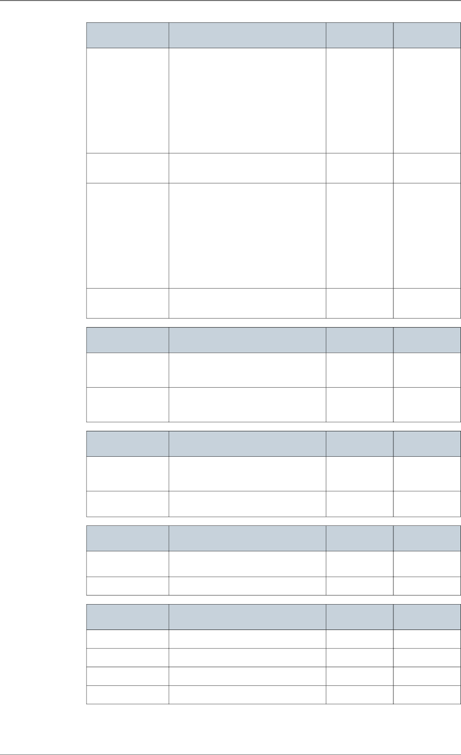
Post-shock mode Values Nominal value "As shipped"
value
LV amplitude – MP1
(V)
0.1-0.25-0.35 (± 80 %)
0.5-0.6-0.75-0.85 (± 30 %)
1-1.1-1.25-1.35-1.5-1.6-1.75-1.85-2-2.1-
2.25-2.35-2.5-2.6-2.75-2.85-3-3.1-3.25-
3.35-3.5-3.6-3.75-3.85-4-4.1-4.25-4.35-
4.5-4.6-4.75-4.85-5-5.1-5.25-5.35-5.5-
5.6-5.75-5.85-6-6.1-6.25-6.35-6.5-6.6-
6.75-6.85-7 (± 20 %)
5 3.5
LV pulse width –
MP1 (ms)
0.12-0.25-0.35-0.5-0.6-0.75-0.85-1-1.1-
1.25-1.35-1.5-1.6-1.75-1.85-2 (± 10 %)
0.35 0.35
LV amplitude – MP2
(V)
0.1-0.25-0.35 (± 80 %)
0.5-0.6-0.75-0.85 (± 30 %)
1-1.1-1.25-1.35-1.5-1.6-1.75-1.85-2-2.1-
2.25-2.35-2.5-2.6-2.75-2.85-3-3.1-3.25-
3.35-3.5-3.6-3.75-3.85-4-4.1-4.25-4.35-
4.5-4.6-4.75-4.85-5-5.1-5.25-5.35-5.5-
5.6-5.75-5.85-6-6.1-6.25-6.35-6.5-6.6-
6.75-6.85-7 (± 20 %)
5 3.5
LV amplitude – MP2
(ms)
0.12-0.25-0.35-0.5-0.6-0.75-0.85-1-1.1-
1.25-1.35-1.5-1.6-1.75-1.85-2 (± 10 %)
0.35 0.35
Refractory periods Values Nominal value "As shipped"
value
Atrial refractory peri-
od post ventricular
sensing (ms)
45-65-80-95-110-125-140-155 (± 16 ms) 45 45
Atrial refractory peri-
od post ventricular
pacing (ms)
80-95-110-125-140-155 (± 4 ms) 80 80
Sensitivity margins Values Nominal value "As shipped"
value
Atrial post pac-
ing/sensing margin
(mV)
From 0 to 1 by steps of 0.2 0.4 0.4
Ventricular post pac-
ing margin (mV)
From 0 to 2 by steps of 0.2 0.8 0.8
Response to noise Values Nominal value "As shipped"
value
Automatic sensitivity
on noise
ON-OFF ON ON
V pacing on noise ON-OFF OFF OFF
SafeR parameters Values Nominal value "As shipped"
value
AVB I switch Rest+Exercise-Exercise Exercise Rest+Exercise
Long PR: max (ms) From 200 to 500 by steps of 50 450 450
Long PR: min (ms) From 200 to 500 by steps of 50 250 250
Max. pause (s) 2-3-4 3 3
21. PROGRAMMABLE PARAMETERS
SORIN – PLATINIUM 4LV SonR CRT-D 1844 – U906A 61

VENTRICULAR TACHYARRHYTHMIA DETECTION
Therapy zones Values Nominal value "As shipped"
value
Slow VT detection
zone
Slow VT ON-Slow VT OFF Slow VT OFF Slow VT OFF
VT detection zone VT ON-VT OFF VT OFF VT OFF
Fast VT / VF detec-
tion zone
Fast VT+VF ON-VF ON VF ON VF ON
Slow VT rate (lower
limit) (ppm)
From 100 to 200 by steps of 5 190 190
VT rate (lower limit)
(ppm)
130-135-140-145-150-155-160-165-170-
175-180-185-190-195-200-210-220-230
190 190
VF rate (lower limit)
(ppm)
150-155-160-165-170-175-180-185-190-
195-200-210-220-230-240
190 190
Fast VT rate (upper
limit) (ppm)
155-160-165-170-175-180-185-190-195-
200-210-220-230-240-255
190 190
Slow VT persistence
(cycles)
4-6-8-12-16-20-30-50-100-200 12 12
VT persistence (cy-
cles)
4-6-8-12-16-20-30-50-100-200 12 12
VF persistence (cy-
cles)
From 4 to 20 by steps of 1 6 6
Detection criteria Values Nominal value "As shipped"
value
Slow VT and VT de-
tection criteria
Rate Only-Stability-Stability+-
Stability/Acc-Stability+/Acc-PARAD-
PARAD+
PARAD PARAD
Fast VT detection
criteria
Rate+Stability-Rate Only Rate+Stability Rate+Stability
Majority: (X/Y), Y
(cycles)
8-12-16 8 8
Majority: (X/Y), X (%) 65-70-75-80-90-95-100 75 75
Window of RR stabil-
ity for Slow VT and
VT (ms)
30-45-65-80-95-110-125 65 65
Window of RR stabil-
ity for fast VT (ms)
30-45-65 30 30
Acceleration (%) 6-13-19-25-31-38-44-50 25 25
Long cycle persis-
tence extension (cy-
cles)
From 0 to 16 by steps of 1 10 10
Long cycle gap (ms) 15-30-45-65-80-95-110-125-140-155-
170-190-205
170 170
Atrial monitoring Yes-No Yes Yes
21.2.
21. PROGRAMMABLE PARAMETERS
62 SORIN – PLATINIUM 4LV SonR CRT-D 1844 – U906A
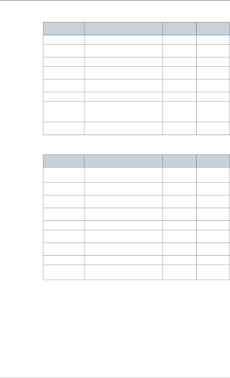
VENTRICULAR TACHYARRHYTHMIA THERAPIES
Common parame-
ters
Values Nominal value "As shipped"
value
Enable ATP therapy Yes-No No No
Enable shock thera-
py
Yes-No Yes No
ATP pacing chamber Right-R+L-L+R Right Right
Polarity alternation
(42J)
Yes-No No No
Atrial coil (SVC) pre-
sent
Yes-No Yes
Active case Yes-No Yes
Shock configuration
(+ --> -)
Case to RV-SVC to RV-
Case + SVC to RV-RV to Case-
RV to SVC-RV to Case + SVC
RV to Case +
SVC
RV to Case +
SVC
SVC exclusion
(shock < 15J)
Yes-No No No
Therapy parameters in slow VT zone
ATP 1 program Values Nominal value "As shipped"
value
ATP program OFF-Burst-Burst+Scan-Ramp-
Ramp+Scan
OFF OFF
Number of se-
quences
1-2-3-4-5-6-7-8-9-10-11-12-13-14-15 3 3
Cycles in first se-
quence
1-2-3-4-5-6-7-8-9-10-11-12-13-14-15 8 8
Cycles added per
sequence
0-1-2-3-4-5-6-7-8-9-10-11-12-13-14-15 0 0
Coupling interval (%) 50-55-60-65-70-75-80-85-90-95 80 80
Ramp decrement
(per cycle) (ms)
0-4-8-12-16-20-30-40-50-60 0 0
Scan decrement (per
sequence) (ms)
0-4-8-12-16-20-30-40-50-60 8 8
Time limit (min) 0.5-1-1.5-2-2.5-3-3.5-4 2 2
Minimum cycle
length (ms)
95-110-125-140-155-170-190-205-220-
235-250-265-280-295-310
220 220
21.3.
21.3.1.
21. PROGRAMMABLE PARAMETERS
SORIN – PLATINIUM 4LV SonR CRT-D 1844 – U906A 63

ATP 2 program Values Nominal value "As shipped"
value
ATP program OFF-Burst-Burst+Scan-Ramp-
Ramp+Scan
OFF OFF
Number of se-
quences
1-2-3-4-5-6-7-8-9-10-11-12-13-14-15 3 3
Cycles in first se-
quence
1-2-3-4-5-6-7-8-9-10-11-12-13-14-15 6 6
Cycles added per
sequence
0-1-2-3-4-5-6-7-8-9-10-11-12-13-14-15 1 1
Coupling interval (%) 50-55-60-65-70-75-80-85-90-95 85 85
Ramp decrement
(per cycle) (ms)
0-4-8-12-16-20-30-40-50-60 8 8
Scan decrement (per
sequence) (ms)
0-4-8-12-16-20-30-40-50-60 0 0
Time limit (min) 0.5-1-1.5-2-2.5-3-3.5-4 2 2
Minimum cycle
length (ms)
95-110-125-140-155-170-190-205-220-
235-250-265-280-295-310
220 220
Shock program Values Nominal value "As shipped"
value
Shock 1 (J) OFF-0.5-0.8-1-1.3-1.5-2-2.5-3-3.5-4-5-6-
7-8-9
10-12-14-16-18-20-22-24-26-28-30-32-
34-42
OFF OFF
Shock 2 (J) OFF-0.5-0.8-1-1.3-1.5-2-2.5-3-3.5-4-5-6-
7-8-9
10-12-14-16-18-20-22-24-26-28-30-32-
34-42
OFF OFF
Number of Max.
Shock (42 J)
OFF-1-2-3-4 OFF OFF
21. PROGRAMMABLE PARAMETERS
64 SORIN – PLATINIUM 4LV SonR CRT-D 1844 – U906A

Therapy parameters in VT zone
ATP 1 program Values Nominal value "As shipped"
value
ATP program OFF-Burst-Burst+Scan-Ramp-
Ramp+Scan
Burst+Scan Burst+Scan
Number of se-
quences
1-2-3-4-5-6-7-8-9-10-11-12-13-14-15 3 3
Cycles in first se-
quence
1-2-3-4-5-6-7-8-9-10-11-12-13-14-15 8 8
Cycles added per
sequence
0-1-2-3-4-5-6-7-8-9-10-11-12-13-14-15 0 0
Coupling interval (%) 50-55-60-65-70-75-80-85-90-95 80 80
Ramp decrement
(per cycle) (ms)
0-4-8-12-16-20-30-40-50-60 0 0
Scan decrement (per
sequence) (ms)
0-4-8-12-16-20-30-40-50-60 8 8
Time limit (min) 0.5-1-1.5-2-2.5-3-3.5-4 0.5 2
Minimum cycle
length (ms)
95-110-125-140-155-170-190-205-220-
235-250-265-280-295-310
220 220
ATP 2 program Values Nominal value "As shipped"
value
ATP program OFF-Burst-Burst+Scan-Ramp-
Ramp+Scan
Ramp Ramp
Number of se-
quences
1-2-3-4-5-6-7-8-9-10-11-12-13-14-15 3 3
Cycles in first se-
quence
1-2-3-4-5-6-7-8-9-10-11-12-13-14-15 6 6
Cycles added per
sequence
0-1-2-3-4-5-6-7-8-9-10-11-12-13-14-15 1 1
Coupling interval (%) 50-55-60-65-70-75-80-85-90-95 85 85
Ramp decrement
(per cycle) (ms)
0-4-8-12-16-20-30-40-50-60 8 8
Scan decrement (per
sequence) (ms)
0-4-8-12-16-20-30-40-50-60 0 0
Time limit (min) 0.5-1-1.5-2-2.5-3-3.5-4 0.5 2
Minimum cycle
length (ms)
95-110-125-140-155-170-190-205-220-
235-250-265-280-295-310
220 220
21.3.2.
21. PROGRAMMABLE PARAMETERS
SORIN – PLATINIUM 4LV SonR CRT-D 1844 – U906A 65

Shock program Values Nominal value "As shipped"
value
Shock 1 (J) OFF-0.5-0.8-1-1.3-1.5-2-2.5-3-3.5-4-5-6-
7-8-9
10-12-14-16-18-20-22-24-26-28-30-32-
34-42
OFF OFF
Shock 2 (J) OFF-0.5-0.8-1-1.3-1.5-2-2.5-3-3.5-4-5-6-
7-8-9
10-12-14-16-18-20-22-24-26-28-30-32-
34-42
OFF OFF
Number of Max.
Shock (42 J)
OFF-1-2-3-4 4 4
Therapy parameters in fast VT / VF zone
ATP 1 program Values Nominal value "As shipped"
value
ATP program OFF-Burst-Burst+Scan-Ramp-
Ramp+Scan
Burst Burst
Number of se-
quences
1-2-3-4-5-6-7-8-9-10-11-12-13-14-15 1 1
Cycles in first se-
quence
1-2-3-4-5-6-7-8-9-10-11-12-13-14-15 8 8
Cycles added per
sequence
0-1-2-3-4-5-6-7-8-9-10-11-12-13-14-15 0 0
Coupling interval (%) 50-55-60-65-70-75-80-85-90-95 80 80
Ramp decrement
(per cycle) (ms)
0-4-8-12-16-20-30-40-50-60 0 0
Scan decrement (per
sequence) (ms)
0-4-8-12-16-20-30-40-50-60 0 0
Time limit 10s-20s-30s-1min-1.5min-2min 30s 30s
Minimum cycle
length (ms)
95-110-125-140-155-170-190-205-220-
235-250-265-280-295-310
205 205
Shock program Values Nominal value "As shipped"
value
Shock 1 (J) OFF-0.5-0.8-1-1.3-1.5-2-2.5-3-3.5-4-5-6-
7-8-9
10-12-14-16-18-20-22-24-26-28-30-32-
34-42
OFF OFF
Shock 2 (J) OFF-0.5-0.8-1-1.3-1.5-2-2.5-3-3.5-4-5-6-
7-8-9
10-12-14-16-18-20-22-24-26-28-30-32-
34-42
OFF OFF
Number of Max.
Shock (42 J)
1-2-3-4 4 4
REMOTE ALERTS AND WARNINGS
The device routinely performs security self-checks and technical measurements to ensure
system integrity. When system integrity is found to be at risk outside a follow-up, alerts are
stored in the device memory. When system integrity is found to be at risk during a follow-
21.3.3.
21.4.
21. PROGRAMMABLE PARAMETERS
66 SORIN – PLATINIUM 4LV SonR CRT-D 1844 – U906A
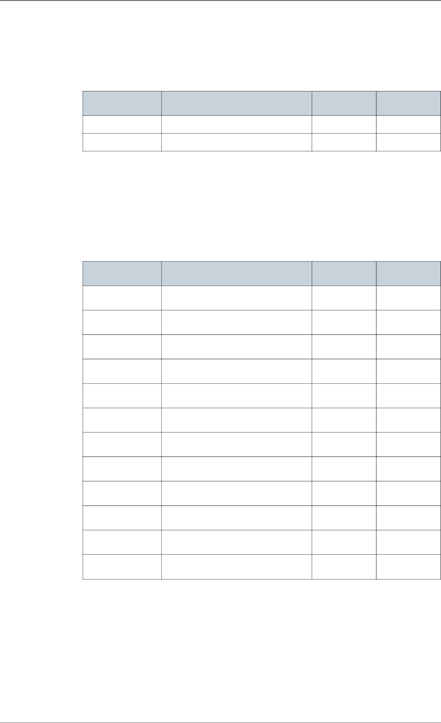
up, the information is managed by a warning (pop-up message) to immediately notify the
user. For example, the following types of events can trigger a warning or an alert: technical
problem during a shock, pacing lead impedance or coil impedance measurements out-of-
range, battery depletion, etc. The Remote tab presents an overview of all the alerts managed
by the device.
General parameters Values Nominal value "As shipped"
value
RF communication (1) ON-OFF ON OFF
Alerts (1) ON-OFF ON ON
(1) RF and Remote alerts are turned on automatically if Shocks are programmed ON.
When Alerts are programmed "On", the following System Alerts are automatically activated:
― “Battery depletion – RRT”
― “Device reset”
― “Excessive charge time (>25s)”
― “System integrity”
Lead Alerts Values Nominal value "As shipped"
value
Abnormal A lead im-
pedance
ON-OFF ON ON
Abnormal A lead low
limit (Ohm)
200-250-300-350-400-450-500 200 200
Abnormal A lead
high limit (Ohm)
1500-1750-2000-2500-3000 3000 3000
Abnormal RV lead
impedance
ON-OFF ON ON
Abnormal RV lead
low limit (Ohm)
200-250-300-350-400-450-500 200 200
Abnormal RV lead
high limit (Ohm)
1500-1750-2000-2500-3000 3000 3000
Abnormal LV lead
impedance
ON-OFF ON ON
Abnormal LV lead
low limit (Ohm)
200-250-300-350-400-450-500 200 200
Abnormal LV lead
high limit (Ohm)
1500-1750-2000-2500-3000 3000 3000
Abnormal RV coil im-
pedance
ON-OFF ON ON
Abnormal SVC coil
impedance
ON-OFF ON ON
Abnormal Shock im-
pedance (1) ON-OFF ON ON
(1) Normal impedance range [20 Ohm-200 Ohm]
21. PROGRAMMABLE PARAMETERS
SORIN – PLATINIUM 4LV SonR CRT-D 1844 – U906A 67

Clinical status Values Nominal value "As shipped"
value
V oversensing ON-OFF OFF OFF
High AT/AF burden ON-OFF OFF OFF
AT/AF limit (on 24h)
(h)
0.5-1-3-6-12-24 6 6
Fast V Rate during
AT/AF
ON-OFF OFF OFF
Fast V Rate limit
(ppm)
80-90-100-110-120 100 100
Fast V Duration limit
(h)
0.5-1-3-6-12-24 1 1
Limited % of V pac-
ing in CRT
ON-OFF OFF OFF
Limited % of V pac-
ing (%)
50-70-80-85-90-95 80 80
Therapy informa-
tion
Values Nominal value "As shipped"
value
Shock disabled ON-OFF ON ON
Shocks delivered OFF-All shocks-Inefficient shock-
Inefficient max shock
All shocks All shocks
ATP delivered ON-OFF OFF OFF
21. PROGRAMMABLE PARAMETERS
68 SORIN – PLATINIUM 4LV SonR CRT-D 1844 – U906A
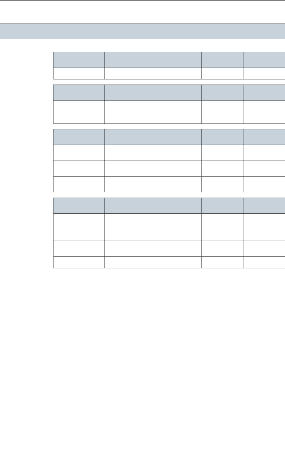
22. NON PROGRAMMABLE PARAMETERS
Interval Values Nominal value "As shipped"
value
Committed period 95 ms (± 5 ms)
Atrial refractory pe-
riods
Values Nominal value "As shipped"
value
Post atrial sensing 47 ms (± 16 ms)
Post atrial pacing 109 ms (± 4 ms)
Ventricular refrac-
tory periods
Values Nominal value "As shipped"
value
Post ventricular
sensing
95 ms (± 16 ms)
Post ventricular pac-
ing
220 ms (± 4 ms)
Post atrial pacing
(blanking)
16 ms (± 3 ms)
Therapies Values Nominal value "As shipped"
value
Waveform (1) Constant tilt (50% - 50%)
Stored energy for the
Max. shock
42 J
Pacing amplitude
during ATP therapies
7 V (Actual value at 300 ms: 5.3 V )
Anti-PMT protection Termin
(1) The device has 50% tilt in each phase thus delivers 94% of stored energy. Each phase is limited
to 10 ms duration.
22. NON PROGRAMMABLE PARAMETERS
SORIN – PLATINIUM 4LV SonR CRT-D 1844 – U906A 69

23. LIMITED WARRANTY
The PLATINIUM implantable cardioverter defibrillator is the result of highly advanced
research and all components have been selected after exhaustive testing.
The terms of the limited warranty are available upon request from your Sorin representative.
23. LIMITED WARRANTY
70 SORIN – PLATINIUM 4LV SonR CRT-D 1844 – U906A

24. PATENTS
The PLATINIUM model described in this manual is covered by the following US patents:
5 713 928, 5 741 315, 5 776 164, 5 776 165, 5 818 703, 5 836 980, 5 868 793, 5 891 170,
5 891 184, 5 899 931, 5 931 856, 5 935 153, 5 954 660, 5 978 708, 6 181 968, 6 230 058,
6 236 111, 6 251 703, 6 256 206, 6 307 261, 6 337 996, 6 397 105, 6 408 209, 6 487 451, 6
487 452, 6 505 068, 6 532 238, 6 556 866, 6 604 002, 6 622 039, 6 625 491, 6 711 441, 6
738 665, 6 830 548, 6 889 080, 6 898 845, 6 912 421, 6 937 898, 6 975 905, 7 065 402, 7
072 716, 7 076 297, 7 113 826, 7 142 924, 7 164 946, 7 251 526, 7 366 566, 7 400 921, 7
400 922, 7 953 483, 8 064 992, 8 043 225, 7 792 582, 8 798 748, 7 890 168, 8 195 293, 7
966 068, 8 768 464, 8 874 209, 8 554 313, 8 214 036, 8 233 981, 8 554 319, 7 966 065, 8
253 279, 8 874 210, 8 219 193, 8 391 976, 8 855 764, 8 359 096, 8 494 629, 8 359 091, 8
489 188, 8 712 526, 8 862 230, 8 641 436, 8 718 765, 8 798 771, 8 868 170, 8 678 843 , 8
694 098, 8 938 286, 8 874 212.
24. PATENTS
SORIN – PLATINIUM 4LV SonR CRT-D 1844 – U906A 71
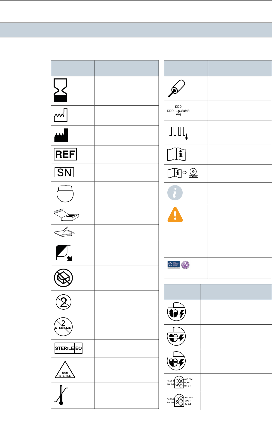
25. EXPLANATION OF SYMBOLS
List of applicable symbols for High-voltage Sorin devices.
General sym-
bols
Explanation of symbols
Use by
Date of manufacture
Manufacturer
Catalogue number
Serial number
Implantable device un-
coated
Package content
Sterile package content
Open here
Do not use if the package
is damaged
Do not reuse
Do not resterilize
Sterilised using ethylene
oxide
Non sterile
Temperature limitation
General sym-
bols
Explanation of symbols
Screwdriver
Mode
Basic rate
Consult instructions for
use
Instructions for use in the
CD-ROM
This icon is used to call
your attention to a partic-
ularly important point.
This icon alerts you to a
hazard that may result in
equipment damage or
personal injury.
Carefully read the in-
structions provided with
this icon.
Eucomed / Advamed
Code of Ethical Business
Practice
Defibrillator
symbols
Explanation of symbols
ICD (CRT-D, RA, RV, LV)
ICD (dual chamber, RA, RV)
ICD (single chamber, RV)
SonR, CRT-D DF-1 connec-
tors
CRT-D DF-1 connectors
25. EXPLANATION OF SYMBOLS
72 SORIN – PLATINIUM 4LV SonR CRT-D 1844 – U906A
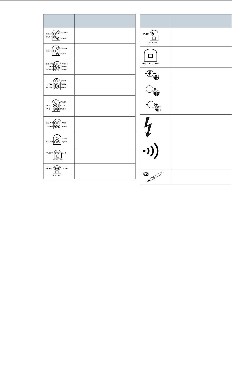
Defibrillator
symbols
Explanation of symbols
DR DF-1 connectors
VR DF-1 connectors
SonR, Tri-V DF-1 connec-
tors
SonR, CRT-D DF-1 connec-
tors
CRT-D DF-1 connectors
DR DF-1 connectors
VR DF-1 connectors
SonR, CRT-D DF4 (IS-1)
connectors
CRT-D DF4 (IS-1) connec-
tors
Defibrillator
symbols
Explanation of symbols
DR DF4 (IS-1) connectors
VR DF4 connector
Shocks
ATP
ATP Anti-tachycardia pacing,
RV, LV
ATP
ATP Anti-tachycardia pacing,
RV
High voltage
Ready for wireless interroga-
tion and programming by Or-
chestra Plus programmer
equipped with ORCHESTRA
PLUS LINK accessory
DF-1 defibrillating connector
insulating plug
Last revision date of this implant manual: 2016-06
25. EXPLANATION OF SYMBOLS
SORIN – PLATINIUM 4LV SonR CRT-D 1844 – U906A 73

Sorin Group Italia S.r.l.
Via Crescentino S.N.
13040 Saluggia (VC)
Italy
Tel: +39 0161 487095
Fax: +39 0161 487524
manufac tured
in ita ly by
www.l iva n ova.com
2016-06
u906a
Sorin CRM USA, Inc.
14401 West 65th Way
Arvada, CO 80004
USA
Tel: 877.663.7674
dis trib u ted
by
CAUTION: FEDERAL LAW RESTRICTS THIS DEVICE TO SALE BY OR ON THE ORDER OF A PHYSICIAN