SORIN CRM DR9550 Implantable cardioverter defibrillator User Manual
SORIN CRM Implantable cardioverter defibrillator Users Manual
UserManual.wiki
>
SORIN CRM
>
DR9550 User Manual
Users Manual
Navigation menu
Upload a User Manual
Namespaces
Wiki Guide
HTML
PDF
Info
Views
User Manual
Discussion / Help
Navigation
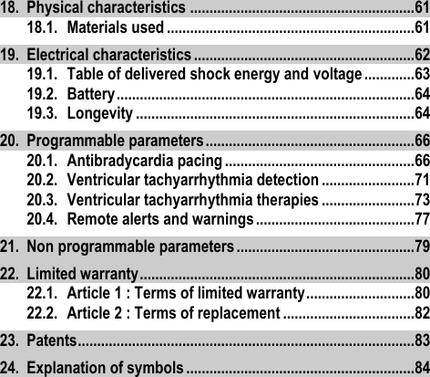
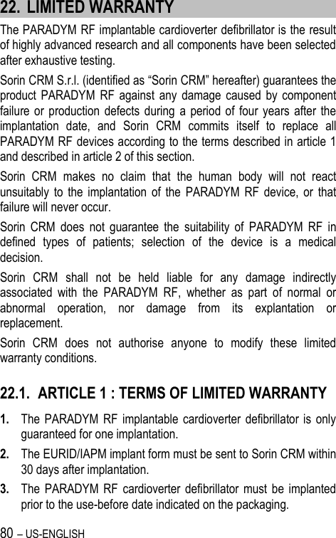
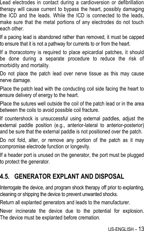
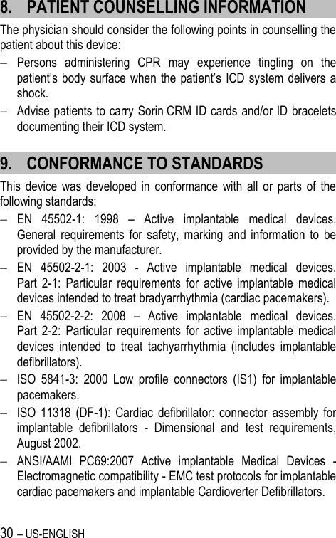
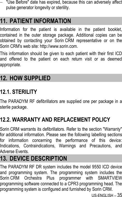
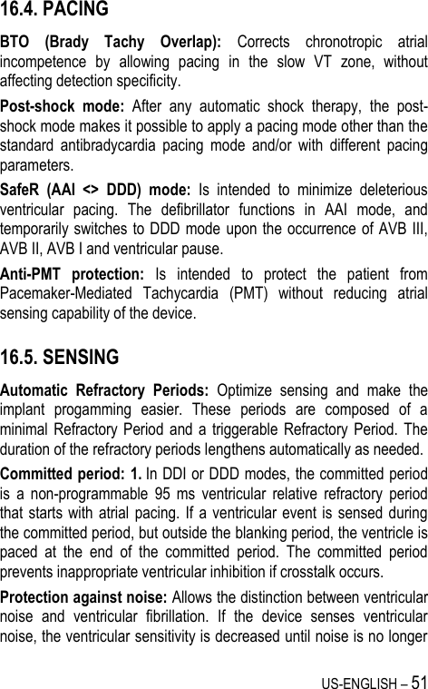
![US-ENGLISH – 9 Electrocautery or diathermy device: Diathermy and electrocautery equipment should not be used. If such devices must be used: 1. Keep the current path and ground plate as far away from the device and the leads as possible (a minimum of 15 cm [six inches]). 2. Before procedure, deactivate ATP and shock therapies. 3. During the procedure, keep the electrocautery device as far as possible from the cardiac defibrillator. Set it at minimum intensity. Use it briefly. 4. After the procedure, check for proper implant function. The device should never be exposed directly to the diathermy source. External defibrillation: PARADYM RF DR 9550 is protected from external defibrillation shocks. Before external defibrillation, deactivate ATP and shock therapies. During external defibrillation, it is advisable to avoid placing the defibrillating paddles directly over the casing or over the leads. The defibrillating paddles should preferably be placed in an anteroposterior position. Avoid any direct contact between the defibrillation paddles and the conductive parts of the implanted leads or casing of the implanted device. After external defibrillation, check for proper device function. Radiation therapy: Avoid exposure to ionizing radiation. Betatrons are contraindicated. If high doses of radiation therapy cannot be avoided, the defibrillator should be protected from direct exposure with a screen. ATP and shock therapies should be disabled during exposure and proper device function should be checked regularly afterwards. Resulting damage may not be immediately detectable. If irradiation of tissues close to the implantation site is necessary, it is recommended that the cardiac defibrillator be moved. As a safety measure, an external defibrillator should be immediately available. Lithotripsy: Lithotripsy may permanently damage the device if this one is at the focal point of the lithotripsy beam. If lithotripsy must be used, keep the defibrillator at least 2.5 to 5 cm (1-2 inches) away from the focal point of the lithotripsy beam.](https://usermanual.wiki/SORIN-CRM/DR9550/User-Guide-1735576-Page-9.png)
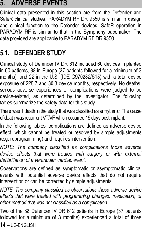
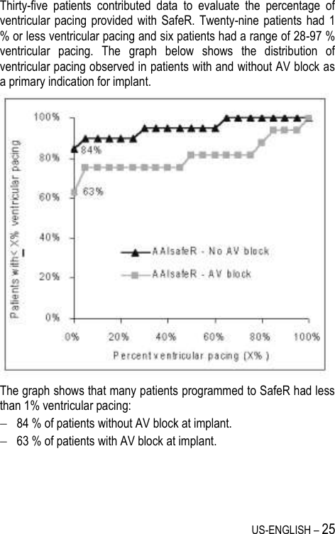
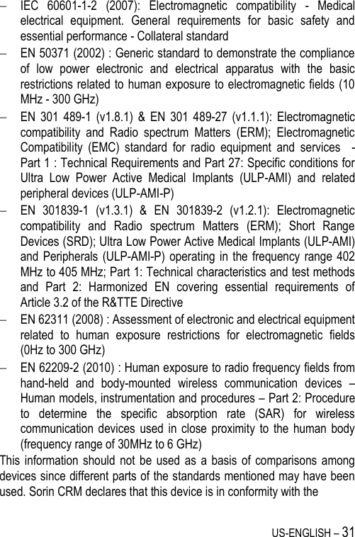

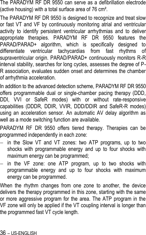
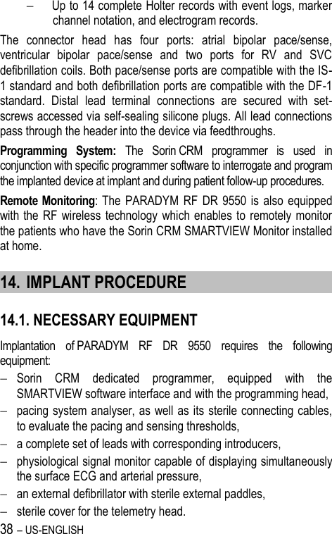
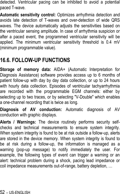
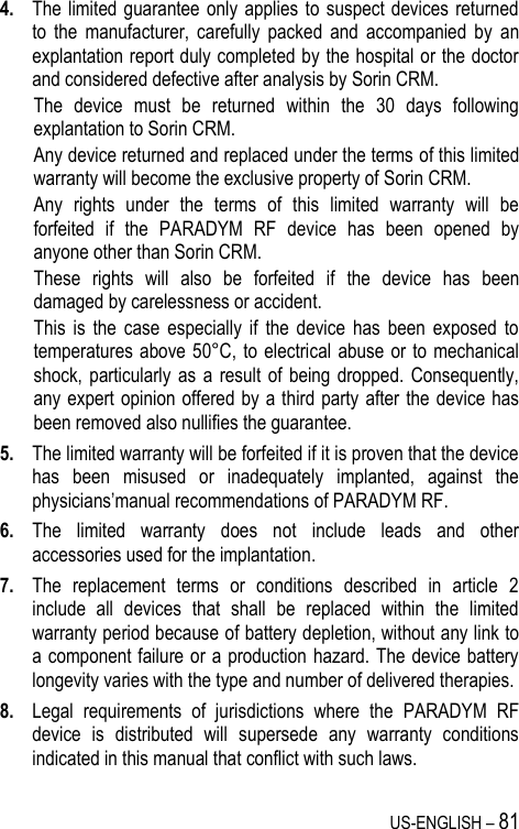
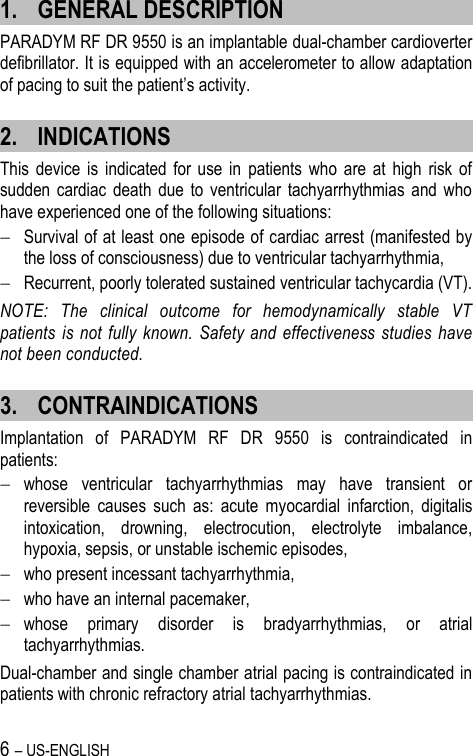
![78 – US-ENGLISH Lead Alerts Values Abnormal A lead impedance ON-OFF Abnormal A lead low limit (Ohm) 200-250-300-350-400-450-500 Abnormal A lead high limit (Ohm) 1500-1750-2000-2500-3000 Abnormal V lead impedance ON-OFF Abnormal V lead low limit (Ohm) 200-250-300-350-400-450-500 Abnormal V lead high limit (Ohm) 1500-1750-2000-2500-3000 Abnormal RV coil impedance ON-OFF Abnormal SVC coil impedance ON-OFF Abnormal Shock impedance (1) ON-OFF (1) Normal impedance range [20 Ohm-200 Ohm] Clinical status Values V oversensing ON-OFF High AT/AF burden ON-OFF AT/AF limit (on 24h) (h) 0.5-1-3-6-12-24 Fast V Rate during AT/AF ON-OFF Fast V Rate limit (min-1) 80-90-100-110-120 Fast V Duration limit (h) 0.5-1-3-6-12-24 Therapy information Values Shock disabled ON-OFF Shocks delivered OFF-All shocks-Inefficient shock-Inefficient max shock](https://usermanual.wiki/SORIN-CRM/DR9550/User-Guide-1735576-Page-78.png)