SORIN CRM VR1210 Implantable cardioverter defibrillator with RF wireless communication availability User Manual
SORIN CRM Implantable cardioverter defibrillator with RF wireless communication availability
User manual
Implantable cardioverter defibrillator
VR models
Implant manual
blank
blank

TABLE OF CONTENTS
1. General description................................................................................................................ 5
2. Indications............................................................................................................................... 6
3. Contraindications....................................................................................................................7
4. Warnings and precautions.....................................................................................................8
4.1. Risks related to medical environment.......................................................................................9
4.2. Sterilization, storage and handling..........................................................................................10
4.3. Implantation and device programming....................................................................................10
4.4. Lead evaluation and lead connection......................................................................................11
4.5. Generator explant and disposal..............................................................................................12
5. Adverse events...................................................................................................................... 13
5.1. Defender study........................................................................................................................ 13
6. Clinical studies...................................................................................................................... 15
6.1. Defender study........................................................................................................................ 15
7. Patient selection and treatment...........................................................................................18
7.1. Individualization of treatment..................................................................................................18
7.2. Specific patient populations....................................................................................................19
8. Patient counselling information..........................................................................................20
9. Declaration of conformity.....................................................................................................21
10. Physician guidelines.............................................................................................................23
10.1. Physician training.................................................................................................................... 23
10.2. Directions for use.................................................................................................................... 23
10.3. Maintaining device quality.......................................................................................................23
11. Patient information............................................................................................................... 24
12. How supplied......................................................................................................................... 25
12.1. Sterility.................................................................................................................................... 25
12.2. Warranty and replacement policy............................................................................................25
13. Device description................................................................................................................ 26
14. Implant procedure................................................................................................................. 28
14.1. Necessary equipment.............................................................................................................28
14.2. Packaging............................................................................................................................... 28
14.3. Optional equipment.................................................................................................................28
14.4. Before opening the package...................................................................................................29
14.5. Prior to implantation................................................................................................................29
14.6. Device placement.................................................................................................................... 29
14.7. Choosing the type of lead.......................................................................................................29
14.8. Shock configuration (+ -> -).....................................................................................................30
14.9. Measurement of thresholds at implant....................................................................................30
14.10.Lead connection ..................................................................................................................... 31
14.11. Device implantation.................................................................................................................32
14.12.Tests and programming...........................................................................................................32
15. Special modes....................................................................................................................... 34
15.1. Safety mode (nominal values).................................................................................................34
15.2. Magnet mode.......................................................................................................................... 34
15.3. Response in the presence of disturbance...............................................................................34
SORIN – PLATINIUM VR – U461A 3

15.4. Detection characteristics in the presence of electromagnetic fields........................................34
15.5. Protection against short-circuits..............................................................................................35
16. Main functions....................................................................................................................... 36
16.1. Automatic lead measurements................................................................................................36
16.2. Ventricular tachyarrhythmia management...............................................................................36
16.3. Pacing..................................................................................................................................... 37
16.4. Sensing................................................................................................................................... 37
16.5. Follow-up function................................................................................................................... 37
16.6. Remote Monitoring function....................................................................................................37
17. Patient follow-up................................................................................................................... 40
17.1. Follow-up recommendations...................................................................................................40
17.2. Holter Function........................................................................................................................ 40
17.3. Recommended Replacement Time (RRT)..............................................................................41
17.4. Explantation............................................................................................................................ 41
17.5. Defibrillator identification.........................................................................................................42
18. Physical characteristics.......................................................................................................43
18.1. Materials used......................................................................................................................... 43
19. Electrical characteristics......................................................................................................44
19.1. Table of delivered shock energy and voltage..........................................................................44
19.2. Battery..................................................................................................................................... 44
19.3. Longevity................................................................................................................................. 45
20. Programmable parameters...................................................................................................47
20.1. Antibradycardia pacing............................................................................................................47
20.2. Ventricular tachyarrhythmia detection.....................................................................................49
20.3. Ventricular tachyarrhythmia therapies.....................................................................................50
20.4. Remote alerts and warnings...................................................................................................53
21. Non programmable parameters...........................................................................................55
22. Limited warranty................................................................................................................... 56
23. Patents................................................................................................................................... 57
24. Explanation of symbols........................................................................................................58
4SORIN – PLATINIUM VR – U461A

1. GENERAL DESCRIPTION
1. GENERAL DESCRIPTION
PLATINIUM VR is an implantable single-chamber cardioverter defibrillator. It is equipped
with an accelerometer to allow adaptation of pacing to suit the patient’s activity.
PLATINIUM VR is also equipped with the RF wireless technology which enables:
─Remote monitoring of patients who have the Sorin SMARTVIEW Monitor installed at
home,
─wireless interrogation and device programming by Orchestra Plus programmer equipped
with ORCHESTRA PLUS LINK accessory.
PLATINIUM VR provides high energy shocks (42 J) for enhanced safety, as well as
automatic lead measurements to monitor system integrity.
PLATINIUM VR is protected against high-frequency signals emitted by cellular telephones.
Device and lead connections:
PLATINIUM VR 1210 1*IS-1 bipolar, 2*DF-1
PLATINIUM VR 1240 1*DF4
SORIN – PLATINIUM VR – U461A 5

2. INDICATIONS
2. INDICATIONS
PLATINIUM VR is indicated for use in patients who are at high risk of sudden cardiac death
due to ventricular tachyarrhythmias and who have experienced one of the following
situations:
─Survival of at least one episode of cardiac arrest (manifested by the loss of
consciousness) due to ventricular tachyarrhythmia,
─Recurrent, poorly tolerated sustained ventricular tachycardia (VT).
6SORIN – PLATINIUM VR – U461A
NOTE: The clinical outcome for hemodynamically stable VT patients is not fully known.
Safety and effectiveness studies have not been conducted.

3. CONTRAINDICATIONS
3. CONTRAINDICATIONS
Implantation of PLATINIUM VR is contraindicated in patients:
─whose ventricular tachyarrhythmias may have transient or reversible causes such as:
acute myocardial infarction, digitalis intoxication, drowning, electrocution, electrolyte
imbalance, hypoxia, sepsis, or unstable ischemic episodes,
─who present incessant tachyarrhythmia,
─who have an internal pacemaker,
─whose primary disorder is bradyarrhythmias, or atrial tachyarrhythmias.
SORIN – PLATINIUM VR – U461A 7

4. WARNINGS AND PRECAUTIONS
4. WARNINGS AND PRECAUTIONS
The patient should be warned of the potential risks of defibrillator malfunction if he is
exposed to external magnetic, electrical, or electromagnetic signals.
These potential interference sources may cause conversion to inhibited mode (because of
noise detection), erratic delivery of VT or VF therapies, nominal programming, or much more
rarely, irreversible damage to the device’s circuits.
The main sources of high magnitude disturbance are: powerful radiofrequency equipment
(radar), industrial motors and transformers, induction furnaces, resistance, arc-welding
equipment and high power loudspeakers.
Electrical Isolation:
Do not permit the patient to contact grounded equipment that could produce hazardous
leakage current. Ensuing arrhythmia induction could result in the patient’s death.
Antitheft gates:
Since antitheft devices at the entrance to stores are not subject to any safety standards, it is
advisable to spend as little time as possible in their vicinity.
Airport detection systems:
Since airport detection systems are not subject to any safety standards, it is advisable to
spend as little time as possible in their vicinity.
Work environment:
The patient's work environment may be an important source of disturbance. In that case,
specific recommendations may be required.
High voltage power transmission lines:
High voltage power transmission lines may generate enough disturbance to interfere with
defibrillator operation if approached too closely.
Communication equipment:
Communication equipment such as microwave transmitters, linear power amplifiers, or high-
power amateur transmitters may generate enough disturbance to interfere with defibrillator
operation if approached too closely.
Home appliances:
Home appliances that are in good working order and properly grounded do not usually
produce enough disturbance to interfere with defibrillator operation. However, there are
reports of device interferences caused by electric hand tools or electric razors used directly
over the device implant site. Patient should also avoid using induction ovens and cookers.
8SORIN – PLATINIUM VR – U461A
CAUTION: Do not tap sharply on the ICD can after implant, because the ICD's sensing
circuits can detect this as R-waves, and such oversensing could result in inappropriate
pacing, inhibition, or therapy. Normal activities after implant do not result in such
oversensing.

4. WARNINGS AND PRECAUTIONS
4.1. RISKS RELATED TO MEDICAL ENVIRONMENT
It is advisable to carefully monitor defibrillator operation prior to and after any medical
treatment during which an electrical current from an external source passes through the
patient's body.
Magnetic Resonance Imaging:
MRI is strictly contraindicated in cardiac defibrillator patients.
Radiofrequency ablation:
A radiofrequency ablation procedure in a patient with a generator may cause device
malfunction or damage. RF ablation risks may be minimized by:
1. Programming Shock Therapy and ATP to OFF.
2. Avoiding direct contact between the ablation catheter and the implanted lead or generator.
3. Positioning the ground, placing it so that the current pathway does not pass through or
near the device, i.e. place the ground plate under the patient’s buttocks or legs.
4. Having external defibrillation equipment available.
Electrocautery or diathermy device:
Diathermy and electrocautery equipment should not be used. If such devices must be used:
1. Keep the current path and ground plate as far away from the device and the lead as
possible (a minimum of 15 cm [six inches]).
2. Before procedure, deactivate ATP and shock therapies.
3. During the procedure, keep the electrocautery device as far as possible from the cardiac
defibrillator. Set it at minimum intensity. Use it briefly.
4. After the procedure, check for proper implant function. The device should never be
exposed directly to the diathermy source.
External defibrillation:
PLATINIUM VR is protected from external defibrillation shocks.
1. Before external defibrillation, deactivate ATP and shock therapies.
2. During external defibrillation, it is advisable to avoid placing the defibrillating paddles
directly over the casing or over the lead. The defibrillating paddles should preferably be
placed in an anteroposterior position.
3. Avoid any direct contact between the defibrillation paddles and the conductive parts of the
implanted leads or casing of the implanted device.
4. After external defibrillation, check for proper device function.
Radiation therapy:
Avoid exposure to ionizing radiation. Betatrons are contraindicated. If high doses of radiation
therapy cannot be avoided, the defibrillator should be protected from direct exposure with a
protection shield. ATP and shock therapies should be disabled during exposure and proper
device function should be checked regularly afterwards. Resulting damage may not be
immediately detectable. If irradiation of tissues close to the implantation site is necessary, it
is recommended that the cardiac defibrillator be moved. As a safety measure, an external
defibrillator should be immediately available.
Lithotripsy:
Lithotripsy may permanently damage the device if it is at the focal point of the lithotripsy
beam. If lithotripsy must be used, keep the defibrillator at least 2.5 to 5 cm (1-2 inches) away
from the focal point of the lithotripsy beam.
SORIN – PLATINIUM VR – U461A 9

4. WARNINGS AND PRECAUTIONS
Diagnostic ultrasound (echography):
The defibrillator is not affected by ultrasound imaging devices.
Scales with body fat monitors and electronic muscle stimulators:
A patient with an implanted PLATINIUM VR should not use these devices.
4.2. STERILIZATION, STORAGE AND HANDLING
Resterilization:
Do not resterilize and re-implant explanted ICDs.
"Use Before" Date:
A "Use Before" date is printed on the outer storage package and on the sterile package. Do
not implant the device after this date because the battery may have reduced longevity and
sterility may be affected. It should be returned to Sorin.
If Package is damaged:
Do not use the device or accessories if the packaging is wet, punctured, opened or
damaged because the integrity of the sterile packaging may be compromised. Return the
device to the manufacturer.
Device Storage:
Store the device in a clean area, away from magnets, kits containing magnets, and sources
of electromagnetic disturbance to avoid device damage. Store the device between 0 - 50 °C
(32 - 122 °F). Temperatures outside the specified range may damage the device.
Equilibration:
Allow the device to reach room temperature before programming or implanting the device
because rapid temperature changes may affect initial device function.
4.3. IMPLANTATION AND DEVICE PROGRAMMING
Use only a Sorin programmer to communicate with the device.
Do not inadvertently position any magnet over the ICD; this suspends tachyarrhythmia
detection and treatment.
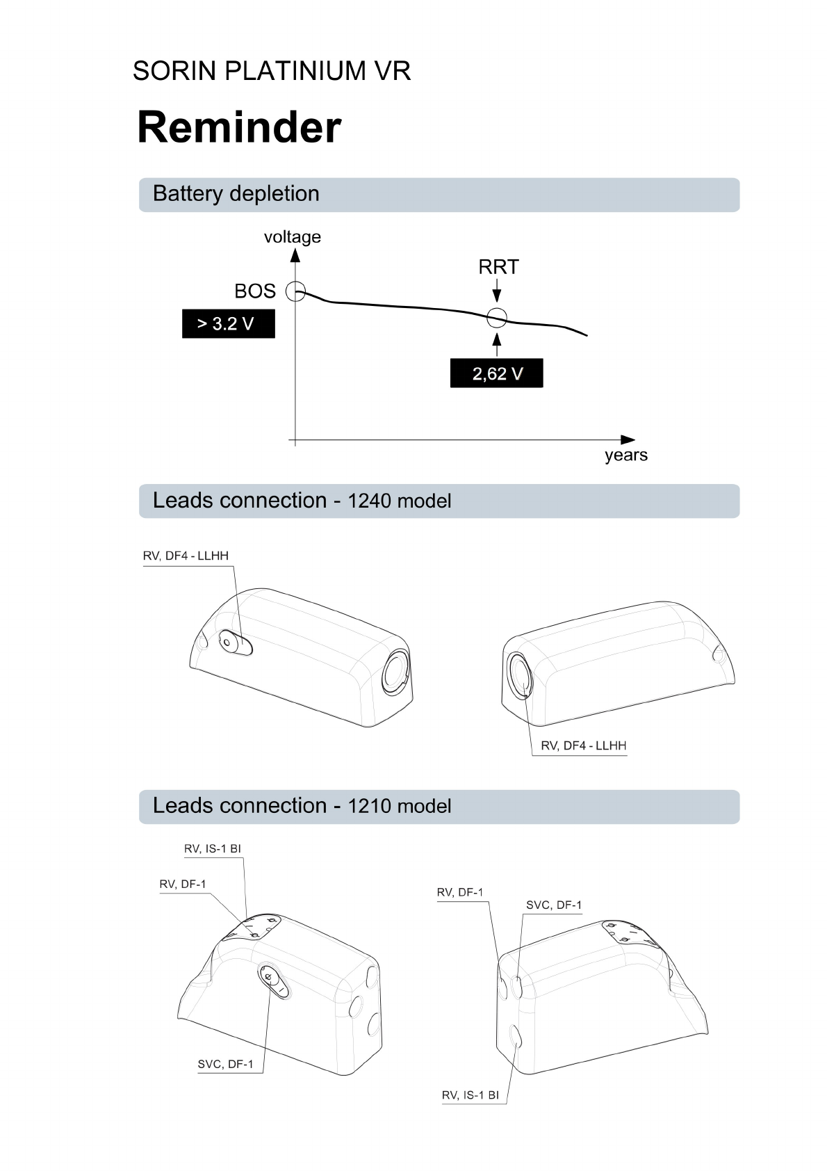
Replace the device when the RRT (Recommended Replacement Time*) point (defined by a
battery voltage of 2.66 ± 0.01 V or a magnet rate lower than or equal to 80 bpm) is reached.
Program device parameters such as sensitivity threshold and VT and VF detection intervals
as specified in the device manuals.
Lead System:
Do not use a lead system other than those with demonstrated compatibility because
undersensing cardiac activity and failure to deliver necessary therapy may result.
In situations where an ICD and a pacemaker are implanted in the same patient, interaction
testing should be completed. If the interaction between the ICD and the pacemaker cannot
be resolved through repositioning of the leads or reprogramming of either the pacemaker or
the ICD, the pacemaker should not be implanted (or should be explanted if previously
implanted).
Failure to properly insert the torque screwdriver into the perforation at an angle
perpendicular to the connector receptacle may result in damage to the sealing system and
its self-sealing properties.
10 SORIN – PLATINIUM VR – U461A

4. WARNINGS AND PRECAUTIONS
In the event of a warning on a low shock impedance, and after lead replacement or
reconnection: it is recommended to check the system integrity (sensing and pacing
thresholds and the impedance of the shock electrodes)
It is recommended that a security margin of at least 10 J be demonstrated between the
effective shock energy and maximum programmable energy. Carefully confirm that true
ventricular fibrillation has been induced because the DFT for ventricular tachycardia or flutter
may be lower.
The defibrillator should be implanted with the engraved side facing outwards in order to
facilitate telemetric communication with the programming head and to display the
radiographic identification correctly.
*: corresponds to ERI (Elective Replacement Indicator) previously used.
4.4. LEAD EVALUATION AND LEAD CONNECTION
PLATINIUM VR 1210 has two DF-1 and one IS-1 connector ports.
PLATINIUM VR 1240 has one DF4 connector port.
IS-1 refers to the international standard whereby leads and generators from different
manufacturers are assured a basic fit (ISO 5841-1:2000).
DF-1 refers to the international standard for defibrillation lead connectors (ISO 11318:2002).
DF4 refers to the international standard for defibrillation lead connectors (ISO 27186:2010).
Use only DF4-LLHH or DF4-LLHO standard lead connector types according to ISO 27186:
2010.
Do not tie a ligature directly to the lead body, tie it too tightly, or otherwise create excessive
strain at the insertion site as this may damage the lead. Use the lead stabilizer to secure the
lead lateral to the venous entry site.
Do not immerse the lead in mineral oil, silicone oil, or any other liquid.
Do not grip the lead with surgical instruments.
Do not use excessive force or surgical instruments to insert a stylet into a lead.
Use ventricular transvenous leads with caution in patients with either a mechanical or
bioprosthetic tricuspid valvular prosthesis.
Use the correct suture sleeve (when needed), to immobilize the lead and protect it against
damage from ligatures.
Never implant the system with a lead system that has a measured shock impedance of less
than 30 ohms. A protection circuit in the defibrillator prevents shock delivery when
impedance is too low. If the shock impedance is less than 30 ohms, reposition the lead
system to allow a greater distance between the electrodes.
Do not kink leads. Kinking leads may cause additional stress on the leads, possibly resulting
in lead fracture.
Do not insert a lead connector pin into the connector block without first visually verifying that
the setscrews are sufficiently retracted. Do not tighten the setscrews unless a lead
connector pin is inserted because it could damage the connector block.
Lead electrodes in contact during a cardioversion or defibrillation therapy will cause current
to bypass the heart, possibly damaging the ICD and the lead. While the ICD is connected to
the lead, make sure that the metal portions of any electrodes do not touch each other.
If a pacing lead is abandoned rather than removed, it must be capped to ensure that it is not
a pathway for currents to or from the heart.
If a thoracotomy is required to place epicardial patches, it should be done during a separate
procedure to reduce the risk of morbidity and mortality.
SORIN – PLATINIUM VR – U461A 11

4. WARNINGS AND PRECAUTIONS
Do not place the patch lead over nerve tissue as this may cause nerve damage.
Place the patch lead with the conducting coil side facing the heart to ensure delivery of
energy to the heart.
Place the sutures well outside the coil of the patch lead or in the area between the coils to
avoid possible coil fracture.
If countershock is unsuccessful using external paddles, adjust the external paddle position
(e.g., anterior-lateral to anterior-posterior) and be sure that the external paddle is not
positioned over the patch.
Do not fold, alter, or remove any portion of the patch as it may compromise electrode
function or longevity.
If a header port is unused on the generator, the port must be plugged to protect the
generator.
4.5. GENERATOR EXPLANT AND DISPOSAL
Interrogate the device, and program shock therapy off prior to explanting, cleaning or
shipping the device to prevent unwanted shocks.
Return all explanted generators and leads to the manufacturer.
Never incinerate the device due to the potential for explosion. The device must be explanted
before cremation.
12 SORIN – PLATINIUM VR – U461A

5. ADVERSE EVENTS
5. ADVERSE EVENTS
Clinical data presented in this section are from the Defender study.
PLATINIUM VR is similar in design and function to the Defender devices.
The data provided are applicable to PLATINIUM VR.
5.1. DEFENDER STUDY
Clinical study of Defender IV DR 612 included 60 devices implanted in 60 patients, 38 in
Europe (37 patients followed for a minimum of 3 months), and 22 in the U.S. (IDE
G970282/S15) with a total device exposure of 228.7 and 30.3 device months, respectively.
No deaths, serious adverse experiences or complications were judged to be device-related,
as determined by the investigator. The following tables summarize the safety data for this
study.
There was 1 death in the study that was classified as arrhythmic. The cause of death was
recurrent VT/VF which occurred 19 days post implant.
In the following tables, complications are defined as adverse device effect, which cannot be
treated or resolved by simple adjustments (e.g. reprogramming) and requires intervention.
Observations are defined as symptomatic or asymptomatic clinical events with potential
adverse device effects that do not require intervention or can be corrected by simple
adjustments.
Two of the 38 Defender IV DR 612 patients in Europe (37 patients followed for a minimum of
3 months) experienced a total of three complications, including device failures and
replacements. Fourteen of the 38 Defender IV DR 612 patients experienced a total of 18
observations. Complications and observations are reported in Tables 1 and 2. It should be
noted that a patient can have more than one observation or complication. There were no
observations or complications in the U.S.
Table 1: Summary of European Clinical Complications
(Including Device Failures and Replacements)
All complications, 2 of 38 Defender IV DR 612 patients in Europe
Event # of Patients % of Patients # of Events Events/100
Device-Years*
Hematoma 1 2.6 1 5.2
Ventricular lead
migration/dislodgment
2 5.3 2 10.5
SORIN – PLATINIUM VR – U461A 13
NOTE: The company classified as complications those adverse device effects that were
treated with surgery or with external defibrillation of a ventricular cardiac event.
NOTE: The company classified as observations those adverse device effects that were
treated with programming changes, medication, or other method that was not classified as a
complication.

5. ADVERSE EVENTS
* There were 228.7 device months in this study.
Table 2: Summary of European Clinical Complications
(Including Patient Complaints)
All complications, 14 of 38 Defender IV DR 612 patients in Europe
Event # of Patients* % of Patients # of Events Events/100
Device-
Years**
Change in ventricular sensing
threshold
1 2.6 1° 5.2
Device reset*** 1 2.6 1° 5.2
Inappropriate therapy for EMI 1 2.6 1° 5.2
Pneumothorax 1 2.6 1° 5.2
Pocket hematoma 2 5.3 2° 10.5
Pocket infection/hematoma 1 2.6 1° 5.2
Pocket infection from previous
pacemaker
1 2.6 1° 5.2
Prolonged implant procedure 1 2.6 1 5.2
Sensor acceleration during
telemetry***
1 2.6 1 5.2
Shock for VT in VF Zone 1 2.6 1° 5.2
Slow VT not converted by ATP
therapy
1 2.6 2° 10.5
Unsatisfactory sensing
threshold test***
2 5.3 2 10.5
Ventricular oversensing 3 7.9 3 15.7
* A patient can have more than one observation.
** There were 228.7 device months in this study.
***These observations would not have happened with the currently marketed device and
programmer.
°Investigator indicated that Defender IV DR did not cause or contribute to the event.
14 SORIN – PLATINIUM VR – U461A

6. CLINICAL STUDIES
6. CLINICAL STUDIES
Clinical data presented in this section are from the Defender study.
PLATINIUM VR is similar in design and function to the Defender devices.
The data provided are applicable to PLATINIUM VR.
6.1. DEFENDER STUDY
Objectives:
The primary objectives of this study were to demonstrate a complication free rate (CFR)
comparable to that of historical controls, to demonstrate, using a chronotropic assessment
exercise protocol (CAEP), a rate response proportional to and appropriate for the level of
exercise, and to evaluate and report the incidence of adverse events.
Materials:
Each patient received one Defender IV DR 612 defibrillator, an atrial pacing and sensing
lead, and a Medtronic, Angeion, or Biotronik defibrillation lead in the U.S. or any
commercially available defibrillator lead outside the U.S.
Methods:
Investigators selected patients who survived at least one episode of cardiac arrest
(manifested by loss of consciousness) presumably due to a ventricular tachyarrhythmia or
exhibited recurrent, poorly tolerated, sustained ventricular tachycardia (VT). The protocol
required evaluation of performance and adverse events at pre-discharge, one month, three
months, six months, and (in the U.S.) every three months thereafter. At the one-month visit,
eligible patients performed a chronotropic assessment exercise protocol (CAEP) maximal
exercise test.
Study Population.
The table below summarizes inclusions.
Region Date of first
implant
Date of last
implant
Data cut-off
date
Number of
centers
Number of
patients
US 14-Dec-99 08-Mar-00 14-Mar-00 6 22
Europe 04-May-99 26-Jul-99 14-Apr-00 11 38
All 04-May-99 08-Mar-00 14-Apr-00 (Eur),
14-Mar-00 (US)
17 60
6.1.1. Complication-free rate
Only European patients followed for at least 3 months:
Symbol Parameter Defender IV DR 612
N Overall number of patients 37
Pe*N Number of successes 35
SORIN – PLATINIUM VR – U461A 15

6. CLINICAL STUDIES
Pe Observed experimental
proportion
0.95
Ps Null hypothesis success rate 0.76
ES Estimated standard error of Pe 0.04
z´ Test statistic (1) 4.75
p Associated p-value < 0,0001
(1) Statistical test: z´ = (Pe-Ps)/SE where SE = sqrt(Pe(1-Pe)/N)
6.1.2. Rate response
European patients only:
GROUP Number of
patients
included
Mean slope
%SRR on
%MR
STD of
slopes
%SRR on
%MR
SE of mean
slope %SRR
on %MR
Lower 95%
CI
Upper 95%
CI
Europe 20 0.77 0.17 0.04 0.69 0.84
Small
Centers
9 0.79 0.18 0.06 0.67 0.91
Large
Centers
11 0.75 0.15 0.05 0.66 0.84
Males 17 0.77 0.16 0.04 0.70 0.85
Females 3 0.73 0.22 0.13 0.47 0.98
SRR: Sensor Rate Reserve
MR: Metabolic Reserve
STD: Standard Deviation
SE: Standard Error
CI: Confidence Interval
6.1.3. Adverse events
Event US (N=22) Number of events* Number of patients Percent of patients
Intent to treat but did
not
0 0 0.0
Non-device related
death
0 0 0.0
Explant 0 0 0.0
Complication 0 0 0.0
Observation 0 0 0.0
Serious non-related
other than death
1 1 4.5
16 SORIN – PLATINIUM VR – U461A

6. CLINICAL STUDIES
Event Europe (N=38) Number of events* Number of patients Percent of patients
Intent to treat but did
not
0 0 0.0
Non-device related
death
1 1 2.6
Explant 1 1 2.6
Complication 3 2 5.3
Observation 18 14 36.8
Serious non-related
other than death
12 7 18.4
Event All (N=60) Number of events* Number of patients Percent of patients
Intent to treat but did
not
0 0 0.0
Non-device related
death
1 1 1.7
Explant 1 1 1.7
Complication 3 2 3.3
Observation 18 14 23.3
Serious non-related
other than death
13 8 13.3
* A patient can have more than one complication, observation, or serious adverse event, not
device-related.
Device Failures and Replacements:
No device failures or replacements occurred with Defender IV DR 612 during the study.
SORIN – PLATINIUM VR – U461A 17

7. PATIENT SELECTION AND TREATMENT
7. PATIENT SELECTION AND TREATMENT
7.1. INDIVIDUALIZATION OF TREATMENT
Exercise stress testing:
If the patient’s condition permits, use exercise stress testing to:
─Determine the maximum rate of the patient’s normal rhythm,
─Identify any supraventricular tachyarrhythmias,
─Identify exercise-induced tachyarrhythmias.
The maximum exercise rate or the presence of supraventricular tachyarrhythmias may
influence selection of programmable parameters. Holter monitoring or other extended ECG
monitoring also may be helpful.
Electrophysiologic (EP) testing:
EP testing may be useful for ICD candidates.
EP testing may identify the classifications and rates of all the ventricular and atrial
arrhythmias, whether spontaneous or during EP testing.
Drug resistant supraventricular tachyarrhythmias (SVTs):
Drug resistant supraventricular tachyarrhythmias (SVTs) may initiate frequent unwanted
device therapy.
A careful choice of programming options is necessary for such patients.
Antiarrhythmic drug therapy:
If the patient is being treated with antiarrhythmic or cardiac drugs, the patient should be on a
maintenance drug dose rather than a loading dose at the time of ICD implantation. If
changes to drug therapy are made, repeated arrhythmia inductions are recommended to
verify ICD detection and conversion. The ICD also may need to be reprogrammed.
Changes in a patient’s antiarrhythmic drug or any other medication that affects the patient’s
normal cardiac rate or conduction can affect the rate of tachyarrhythmias and/or efficacy of
therapy.
Direct any questions regarding the individualization of patient therapy to Sorin’s
representative.
18 SORIN – PLATINIUM VR – U461A
CAUTION: To avoid inappropriate therapy during an exercise stress test, do not reprogram
any parameter during the test. When a parameter is reprogrammed, algorithm forces
acceleration to "ventricular". During conducted sinus tachycardia within the programmed
Tachy zone, the device detects a 1:1 fast rhythm. Assuming that acceleration was set to
ventricular by reprogramming, the device may identify this as a VT, and may immediately
apply the corresponding therapy.

7. PATIENT SELECTION AND TREATMENT
7.2. SPECIFIC PATIENT POPULATIONS
Pregnancy:
If there is a need to image the device, care should be taken to minimize radiation exposure
to the foetus and the mother.
Nursing Mothers:
Although appropriate biocompatibility testing has been conducted for this implant device,
there has been no quantitative assessment of the presence of leachables in breast milk.
Pediatric Patients:
This device has not been studied in patients younger than 18 years of age.
Geriatric Patients:
Most of the patients receiving this device in clinical studies were over the age of 60 years.
Handicapped and Disabled Patients:
Special care is needed in using this device for patients using an electrical wheel chair or
other electrical (external or implanted) devices.
SORIN – PLATINIUM VR – U461A 19

8. PATIENT COUNSELLING INFORMATION
8. PATIENT COUNSELLING INFORMATION
The physician should consider the following points in counselling the patient about this
device:
─Persons administering CPR may experience tingling on the patient’s body surface when
the patient’s ICD system delivers a shock.
─Advise patients to carry Sorin ID cards and/or ID bracelets documenting their ICD
system.
20 SORIN – PLATINIUM VR – U461A

9. DECLARATION OF CONFORMITY
9. DECLARATION OF CONFORMITY
Sorin declares that this device is in conformity with the essential requirements of Directive
1999/5/EC on Radio and Telecommunications Terminal Equipment, with the mutual
recognition of their conformity (R&TTE).
Federal Communication Commission Interference Statement 47 CFR Section 15.19
and 15.105(b)
The FCC product ID is :
─PLATINIUM VR 1210: YSGVR1210
─PLATINIUM VR 1240: YSGVR1240
This equipment has been tested and found to comply with the limits for a Class B digital
device, pursuant to Part 15 of the FCC Rules. These limits are designed to provide
reasonable protection against harmful interference in a residential installation. This
equipment generates uses and can radiate radio frequency energy and, if not installed and
used in accordance with the instructions, may cause harmful interference to radio
communications. However, there is no guarantee that interference will not occur in a
particular installation.
This device complies with Part 15 of the FCC Rules. Operation is subject to the following
two conditions: (1) This device may not cause harmful interference, and (2) this device must
accept any interference received, including interference that may cause undesired
operation.
FCC Interference Statement 47 CFR Section 15.21 - No Unauthorized Modifications
Identification of the equipment according Section 95.1217(a)
This transmitter is authorized by rule under the Medical Device Radiocommunication Service
(in part 95 of the FCC Rules) and must not cause harmful interference to stations operating
in the 400.150-406.00 MHz band in the Meteorological Aids (i.e., transmitters and receivers
used to communicate weather data), the Meteorological Satellite, or the Earth Exploration
Satellite Services and must accept interference that may be caused by such stations,
including interference that may cause undesired operation. This transmitter shall be used
only in accordance with the FCC Rules governing the Medical Device Radiocommunication
Service. Analog and digital voice communications are prohibited. Although this transmitter
has been approved by the Federal Communications Commission, there is no guarantee that
it will not receive interference or that any particular transmission from this transmitter will be
free from interference.
IC Requirements for Canada
The FCC product ID is :
─PLATINIUM VR 1210: 10270A-VR1210
─PLATINIUM VR 1240: 10270A-VR1240
This class B digital apparatus meets all requirements of the Canadian Interference- causing
equipment regulations.
SORIN – PLATINIUM VR – U461A 21
CAUTION: This equipment may not be modified, altered, or changed in any way without
signed written permission from SORIN. Unauthorized modification may void the equipment
authorization from the FCC and will void the SORIN warranty.

9. DECLARATION OF CONFORMITY
This device complies with Industry Canada licence-exempt RSS standard(s). Operation is
subject to the following two conditions: (1) this device may not cause interference, and (2)
this device must accept any interference, including interference that may cause undesired
operation of the device.
Under Industry Canada regulations, this radio transmitter may only operate using an
antenna of a type and maximum (or lesser) gain approved for the transmitter by Industry
Canada. To reduce potential radio interference to other users, the antenna type and its gain
should be so chosen that the equivalent isotropically radiated power (e.i.r.p.) is not more
than that necessary for successful communication.
This device may not interfere with stations operating in the 400.150–406.000 MHz band in
the Meteorological Aids, Meteorological Satellite, and Earth Exploration Satellite Services
and must accept any interference received, including interference that may cause undesired
operation.
Cet appareil numérique de la classe B respecte toutes les exigences du règlement sur le
matériel brouilleur du Canada.
Le présent appareil est conforme aux CNR d’Industrie Canada applicables aux appareils
radio exempts de licence. L’exploitation est autorisée aux deux conditions suivantes: (1) il ne
doit pas produire de brouillage, et (2) l’utilisateur du dispositif doit être prêt a accepter tout
brouillage radioélectrique reçu, même si ce brouillage est susceptible de compromettre le
fonctionnement du dispositif.
Conformément à la réglementation d’Industrie Canada, le présent émetteur radio peut
fonctionner avec une antenne d’un type et d’un gain maximal (ou inférieur) approuvé pour
l’émetteur par Industrie Canada. Dans le but de réduire les risques de brouillage
radioélectrique à l’ intention d’autres utilisateurs, il faut choisir le type d’antenne et son gain
de sorte que la puissance isotrope rayonnée équivalente (p.i.r.e.) ne dépasse pas l’intensité
nécessaire à l’établissement d’une communication satisfaisante.
Le présent dispositif ne doit pas causer de brouillage aux stations du service des auxiliaires
de la météorologie, des satellites météorologiques, du service d’exploration de la terre par
satellite, exploitées dans la bande 400,150-406,000 MHz, et il doit accepter tout brouillage
reçu, y compris le brouillage pouvant entraîner un mauvais fonctionnement du dispositif.
22 SORIN – PLATINIUM VR – U461A

10. PHYSICIAN GUIDELINES
10. PHYSICIAN GUIDELINES
10.1. PHYSICIAN TRAINING
Physicians should be familiar with sterile pulse generator implant procedure and familiar with
follow-up evaluation and management of patients with an implantable defibrillator (or referral
to such a physician).
10.2. DIRECTIONS FOR USE
ICD operating characteristics should be verified at the time of implantation and recorded in
the patient file. Complete the Patient Registration Form and return it to Sorin, as it provides
necessary information for warranty purposes and patient tracking.
Additional programming instructions can be found by accessing Online Help (click the “?” on
the screen) on the Sorin dedicated programmer. Paper copies of Online Help can be
obtained by contacting your Sorin representative.
10.3. MAINTAINING DEVICE QUALITY
This device is FOR SINGLE USE ONLY. Do not resterilize and reimplant explanted ICDs.
Do not implant the device when:
─It has been dropped on a hard surface because this could have damaged pulse
generator components.
─Its sterility indicator within the inner package is not green, because it might not have
been sterilized.
─Its storage package has been pierced or altered, because this could have rendered it
non-sterile.
─It has been stored or transported outside the environmental temperature limits: 32 °F (0
°C) to 122 °F (50 °C) as an electrical reset condition may occur.
─"Use Before" date has expired, because this can adversely affect pulse generator
longevity or sterility.
SORIN – PLATINIUM VR – U461A 23

11. PATIENT INFORMATION
11. PATIENT INFORMATION
Information for the patient is available in the patient booklet, contained in the outer storage
package. Additional copies can be obtained by contacting your Sorin representative.
This information should be given to each patient with their first ICD and offered to the patient
on each return visit or as deemed appropriate.
24 SORIN – PLATINIUM VR – U461A

12. HOW SUPPLIED
12. HOW SUPPLIED
12.1. STERILITY
The PLATINIUM defibrillators are supplied one per package in a sterile package.
12.2. WARRANTY AND REPLACEMENT POLICY
Sorin warrants its defibrillators. Refer to the section "Warranty" for additional information.
Please see the following labelling sections for information concerning the performance of
this device: Indications, Contraindications, Warnings and Precautions, and Adverse Events.
SORIN – PLATINIUM VR – U461A 25

13. DEVICE DESCRIPTION
13. DEVICE DESCRIPTION
The PLATINIUM VR ICD device and programming system. The programming system
includes the Sorin dedicated programmer with the SMARTVIEW programming software
connected to a CPR3 programming head. The programming system is configured and
furnished by Sorin.
The PLATINIUM VR can serve as a defibrillation electrode (active housing) with a total
surface area of 63 cm².
The PLATINIUM VR is designed to recognize and treat slow or fast VT and VF by
continuously monitoring ventricular activity to identify persistent ventricular arrhythmias and
to deliver appropriate therapies. PLATINIUM VR features DISCRIMINATION algorithm,
which is specifically designed to differentiate ventricular tachycardias from fast rhythms of
supraventricular origin. DISCRIMINATION continuously monitors R-R interval stability,
searches for long cycles and evaluates sudden onset.
In addition to the advanced detection scheme, PLATINIUM VR offers programmable single-
chamber pacing therapy with or without rate-responsive capabilities using an acceleration
sensor.
PLATINIUM VR offers tiered therapy. Therapies can be programmed independently in each
zone:
─in the Slow VT and VT zones: two ATP programs, up to two shocks with programmable
energy and up to four shocks with maximum energy can be programmed;
─in the VF zone: one ATP program, up to two shocks with programmable energy and up
to four shocks with maximum energy can be programmed.
When the rhythm changes from one zone to another, the device delivers the therapy
programmed in this zone, starting with the same or more aggressive program for the area.
The ATP program in the VF zone will only be applied if the VT coupling interval is longer
than the programmed fast VT cycle length.
The PLATINIUM VR offers biphasic shocks with a maximum stored energy of 42 J. The
shock configuration (electrodes used to apply the shock) can be chosen by programming
one of the following combinations: can and one coil, can and two coils, two coils only.
Other features are as follows:
─Automatic ventricular sensitivity control
─Non-committed shocks
─Electrophysiological studies (EPS) with real-time markers or electrograms:
─Programmer-controlled VT induction sequences,
─Programmer-controlled VF inductions (30 Hz rapid pacing or shock on T),
─Programmable electrogram vectors (RV coil-CAN / SVC coil-CAN /RV coil-SVC
coil /RV tip-CAN / RV ring-CAN) and RV EGM,
─Real-time annotations displayed with the markers and indicating the majority rhythm,
─Manual ATP sequences,
─Manual shocks.
─Rescue shock
─Follow-up tests:
─Pacing lead impedance,
26 SORIN – PLATINIUM VR – U461A

13. DEVICE DESCRIPTION
─Coil impedance,
─Capacitor charge time,
─Pacing threshold tests.
─Data storage:
─Therapy History Report,
─Statistics (pace/sense, therapy, shocks, and battery voltage),
─Up to 16 complete Holter records with event logs, marker channel notation, and
electrogram records.
The PLATINIUM VR 1210 connector has three ports:
─ventricular bipolar pace/sense and
─two ports for RV and SVC defibrillation coils.
The PLATINIUM VR 1240 connector head has one port: ventricular bipolar pace/sense and
RV & SVC defibrillation coils.
The pace/sense port is compatible with the IS-1 standard and both defibrillation ports are
compatible with the DF-1 standard.
The defibrillation port is compatible with the DF-1 standard.
Distal lead terminal connections are secured with set-screws accessed via self-sealing
silicone plugs. All lead connections pass through the header into the device via
feedthroughs.
Programming System:
The Sorin programmer is used in conjunction with specific programmer software to
interrogate and program the implanted device at implant and during patient follow-up
procedures.
Remote Monitoring:
PLATINIUM VR is also equipped with the RF wireless technology which enables to remotely
monitor the patients who have the Sorin SMARTVIEW Monitor installed at home.
SORIN – PLATINIUM VR – U461A 27

14. IMPLANT PROCEDURE
14. IMPLANT PROCEDURE
14.1. NECESSARY EQUIPMENT
Implantation of PLATINIUM VR requires the following equipment:
─Sorin ORCHESTRA programmer, equipped with the SMARTVIEW software interface
and inductive telemetry head,
─Sorin ORCHESTRA PLUS programmer, equipped with the SMARTVIEW software
interface, inductive telemetry head and optionally ORCHESTRA PLUS LINK,
─pacing system analyzer, as well as its sterile connecting cables, to evaluate the pacing
and sensing thresholds,
─a ventricular pacing and defibrillation lead,
─physiological signal monitor capable of displaying simultaneously the surface ECG and
arterial pressure,
─an external defibrillator with sterile external paddles,
─sterile cover for the telemetry head.
14.2. PACKAGING
14.2.1. Contents
PLATINIUM VR and its accessories are ethylene oxide sterilized and hermetically sealed in
two-ply clear packaging meeting international requirements.
The sterile packaging contains:
─the defibrillator
─a ratcheting screwdriver
─a DF-1 defibrillating connector insulating plug for 1210 model
Once delivered, PLATINIUM VR is programmed to as-shipped values that are different from
nominal values (see Chapter “Programmable Parameters” for details).
14.3. OPTIONAL EQUIPMENT
The following equipment may be required during implantation of PLATINIUM VR:
─a DF4/DF-1 adaptor in case of replacement and use of DF-1 lead in a DF4 connector
─sterile water to clean traces of blood. Any parts cleaned with sterile water must be
thoroughly dried.
─mineral oil to lubricate if necessary
─a lead cap to isolate a lead which is not used
28 SORIN – PLATINIUM VR – U461A
NOTE: In case you’re implanting a DF4 lead, please verify its compatibility with standard
alligators pin; please refer to the lead user’s manual for more details.

14. IMPLANT PROCEDURE
14.4. BEFORE OPENING THE PACKAGE
Before opening the package, check the "Use Before" date printed on the labels on the box
and on the sterile package. Defibrillators that have not been implanted before that date
should be returned to Sorin.
Interrogate the device:
─if a warning is displayed, do not implant the device and contact your Sorin
representative.
─if battery voltage is below 3V, and if the last reforming/charge occurred more than one
week ago, do not implant the device. Otherwise wait for one more week before checking
the voltage.
NOTE : The battery voltage can decrease before the expiration date is reached. However,
the battery voltage should be equal to or higher than 3V at the time of implant.
Devices MUST NOT be interrogated and programmed within the vicinity of other devices.
Also check the integrity of the sterile package. The sterility of the contents is no longer
guaranteed if the package has been pierced or altered. If the defibrillator is no longer sterile,
it should be returned in its packaging to Sorin. Any re-sterilization of the unit is at the
discretion of Sorin.
14.5. PRIOR TO IMPLANTATION
Use the programmer to verify the defibrillator can be interrogated before implantation.
Verify all shock therapies are disabled in order to avoid accidental discharge during
implantation.
It is not advisable to program the Smoothing function before implantation, since the
defibrillator may detect noise and pace at a rate higher than the programmed basic rate.
14.6. DEVICE PLACEMENT
The pocket should be prepared in the left pectoral position, either subcutaneously or
submuscularly. Subcutaneous device implantation is recommended for optimal RF
communication efficacy.
Implantation in an abdominal position is not advisable.
In its final position, the defibrillator should be no more than 4 cm below the skin surface.
14.7. CHOOSING THE TYPE OF LEAD
The defibrillator should be connected to:
─one right ventricular lead with bipolar sensing/pacing electrodes and one or two
defibrillation coils
SORIN – PLATINIUM VR – U461A 29
CAUTION:
Do not shake or tap sharply on the ICD package with the ICD inside, because the ICD's
sensing circuits can interpret this as R-waves and record these as an arrhythmia episode.
High voltage capacitors charge performed on ICD without connected leads using wireless
telemetry can generate false R-waves detection.
It is recommended to reset the memory data and statistics before implanting the ICD.
14. IMPLANT PROCEDURE
Connectors:
PLATINIUM VR 1210:
The pacing/sensing connector is compatible with the IS-1 standard and the right ventricular
defibrillation connectors are compatible with DF-1 standard.
PLATINIUM VR 1240:
The quadripolar right ventricular connector is compatible with the DF4 standard.
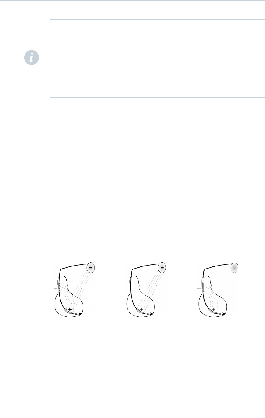
14.8. SHOCK CONFIGURATION (+ -> -)
The shock configuration is the energy pathway between the defibrillation electrodes. If an
atrial coil is present, the shock configuration can be programmed for bi-directional shocks.
Programming:
When active case and SVC are both programmed to Yes, the shock configuration can be
programmed to:
─RV to Case (or Case to RV),
─or RV to SVC (or SVC to RV),
─or RV to Case+SVC (or Case+SVC to RV).
RV to Case+SVC RV to Case RV to SVC
The polarity of shock is determined by the parameter itself.
14.9. MEASUREMENT OF THRESHOLDS AT IMPLANT
Pacing and sensing thresholds should be measured at implant.
Pacing threshold:
Acute threshold should be lower than 1 V (or 2 mA) for a 0.35 ms pulse width.
30 SORIN – PLATINIUM VR – U461A
NOTE 1: Please note that DF-1 standard compliant lead is not compatible with DF4
connector. In the reverse, DF4 standard compliant lead is not compatible with DF-1
connector. In case of defibrillator replacement, choose the appropriate device compatible
with DF-1 or DF4 leads. For any other lead type that require an adaptor for this device,
please contact your Sorin representative for any information on lead / connector
compatibility question.
NOTE 2: In the event of a warning on a low shock impedance, and after lead replacement or
reconnection: it is recommended to check the system integrity (sensing and pacing
thresholds and the impedance of the shock electrodes).

14. IMPLANT PROCEDURE
Sensing threshold:
For appropriate ventricular sensing, the amplitude of the R-wave should be greater than 5
mV.
Pacing impedance measurement:
Ventricular pacing impedance should range from 200 to 3000 ohms (refer to the lead
characteristics, especially if high impedance lead is used).
Please refer to the lead user manual for more details on the expected electrical
performances of the leads.
14.10. LEAD CONNECTION
Implant the ventricular lead.
The lead must be connected to the corresponding connector port. The position of each
connector is indicated on the casing.
Tighten only the distal insert.
To connect the lead, proceed as follows:
1. Clean the lead terminal pins thoroughly, if necessary (device replacement).
2. Lubricate the lead terminal pins with sterile water, if necessary.
3. Do not insert a lead connector pin into the connector block without first visually verifying
that the lead port is not filled with any obstacle.
4. Insert the screwdriver into the pre-inserted screw socket of the appropriate port (in order
to allow excess air to bleed out and to make the insertion of the lead pin easier).
5. Insert the lead pin all the way into the port (check that the pin protrudes beyond the distal
insert).
6. Tighten, check the tightness and ensure the lead pin still protrudes beyond the distal
insert, and has not move.
1. Do not tighten the pre-inserted screws when there is no lead (this could damage the
connector).
2. Do not loosen the screws before inserting the connector (subsequent risk of being unable
to reinsert the screw).
3. When mineral oil or sterile water is used to make lead insertion easier, the screwdriver
should remain inserted into the pre-inserted screw socket when checking the tightness.
As a matter of fact, when the lead port is filled with a liquid, the physics piston effect can
give the feeling the lead is properly tightened.
4. One single set screw is located on the side of the connection header.
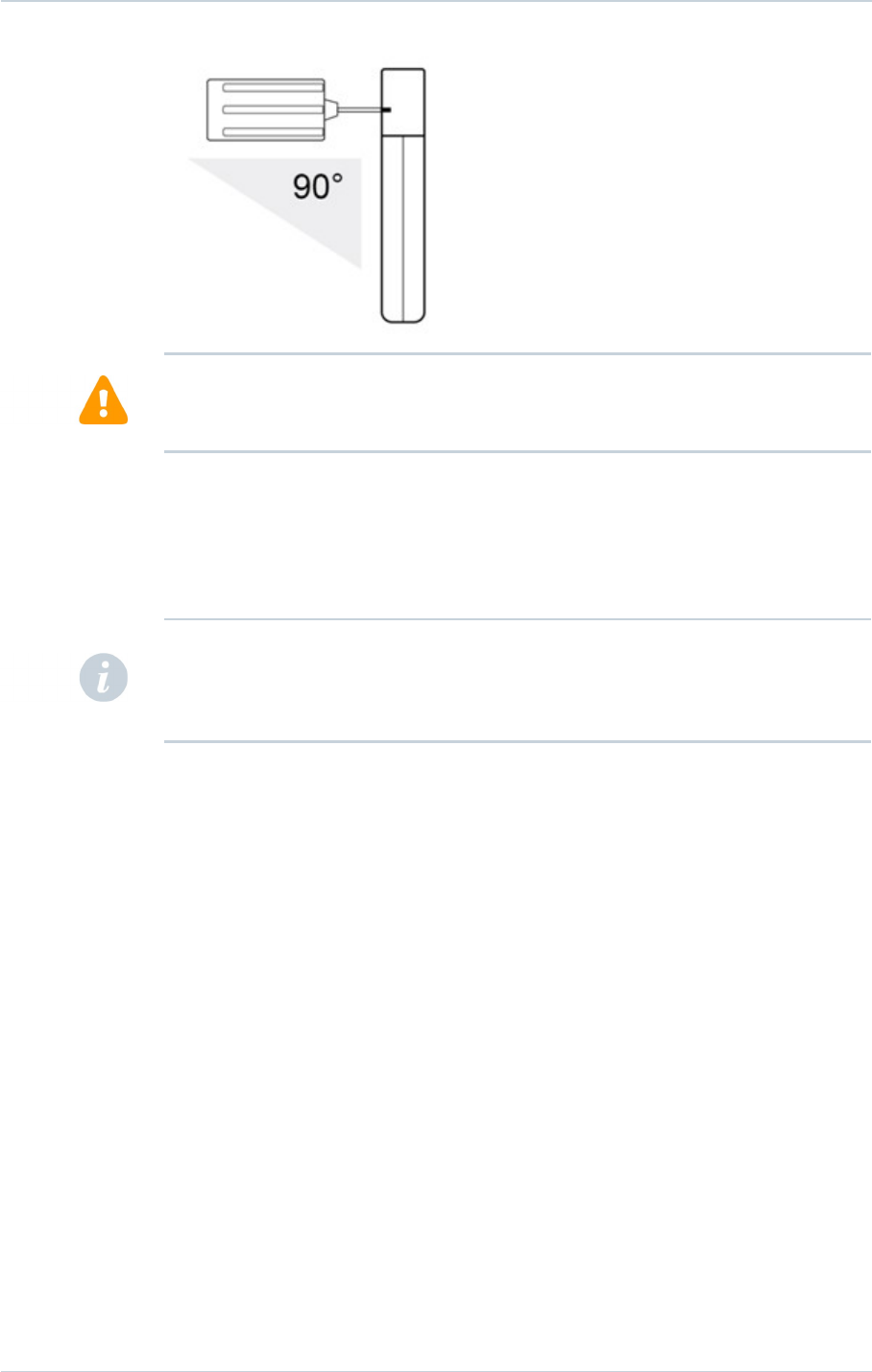
5. Use only the screwdriver provided with the defibrillator. Keep the screwdriver's shaft
perpendicular to the plane of the defibrillator (see figure below).
6. Removing the screwdriver: to avoid all risk of loosening screws during removal, hold the
screwdriver by its metal part and not by the handle.
SORIN – PLATINIUM VR – U461A 31
CAUTION:
CAUTION:
14. IMPLANT PROCEDURE
To ensure full insertion, push the screwdriver's hex tip smoothly into the setscrew until it
reaches the bottom of the hex chamber in the screw, which can be felt as a solid metallic
contact. Do not implant the defibrillator if there is no feeling of solid metallic contact. Do not
implant the defibrillator if the wrench does not click when attempting to tighten the setscrew
on the lead pin.
In the case of an external defibrillation shock delivered to the patient, always check the
programming and functioning of the device, in particular its capacity to deliver shocks.
14.11. DEVICE IMPLANTATION
PLATINIUM VR should be implanted with the device identification engraved side facing
outwards for optimal communication with the programming head and radiographic
identification.
Carefully wind excess lead and place in a separate pocket to the side of the defibrillator.
It is recommended not to place any excess wire between the can and the heart.
Suture the casing connector to the muscle using the hole provided for this purpose, in order
to avoid potential migration of the device into the pectoral muscle.
14.12. TESTS AND PROGRAMMING
During the implant testing procedure:
It is recommended that a security margin of at least 10 J be demonstrated between the
effective shock energy and maximum programmable energy.
Enable shock therapies, then program the defibrillator.
Verify that the defibrillation lead impedance for each shock delivered is within the range of
30 to 150 ohms. Check the lead connection if the values are outside these boundaries.
32 SORIN – PLATINIUM VR – U461A
WARNING: Ensure that the screwdriver's tip is fully inserted in the setscrew; otherwise the
screwdriver can damage the setscrew and prevent connection with or disconnection from
the lead.
NOTE: To optimize cardioversion/defibrillation shocks, electrodes must be positioned so that
the electric field between anode(s) and cathode covers the largest myocardial mass. In
normal conditions, the anode and cathode are adequately separated. In case of a short-
circuit, the shock may be aborted to prevent damaging the defibrillator.

14. IMPLANT PROCEDURE
Save the programming data on the programmer’s hard disk and on an external storage
device (if desired).
Resuscitation Availability:
Do not perform device testing unless an external defibrillator is available and medical
personnel skilled in cardiopulmonary resuscitation (CPR) are present.
Disable the ICD During Handling:
Program Shock Therapy to OFF during surgical implant and explant or post mortem
procedures. The device can deliver a serious high energy shock should accidental contact
be made with the defibrillation electrodes, the device can deliver a very high energy shock.
SORIN – PLATINIUM VR – U461A 33

15. SPECIAL MODES
15. SPECIAL MODES
15.1. SAFETY MODE (NOMINAL VALUES)
Nominal values may be rapidly restored by pressing the following button on the
programming head or programmer keyboard:
or via the Emergency button on the SMARTVIEW screen.
In safety mode, the defibrillator operates with the parameters underlined in the table of
programmable parameters.
15.2. MAGNET MODE
When the magnet is applied:
─antiarrhythmia functions are inhibited (detection of rhythm disturbances, charging, and
therapy),
─pacing amplitude is set to 6 V,
─pulse width is set to maximum,
─the following functions are disabled: Smoothing, Rate Response.
When the magnet is removed:
─arrhythmia detection algorithms and sequential therapies are reinitialized,
─therapies start with the least aggressive program for each area.
The antiarrhythmia functions inhibition is extended after magnet removal if a charge
occurred just before the application of the magnet in order to ease the communication
between the device and the programmer.
The other parameters remain at their programmed value.
15.3. RESPONSE IN THE PRESENCE OF DISTURBANCE
If the defibrillator senses electrical noise at a frequency above 16 Hz, it switches to an
asynchronous mode at the basic rate. The programmed mode is restored as soon as the
noise is no longer detected.
Ventricular pacing may also be inhibited by ventricular noise. It can be restored by setting
the parameter V pacing on noise to Yes.
15.4. DETECTION CHARACTERISTICS IN THE PRESENCE OF
ELECTROMAGNETIC FIELDS
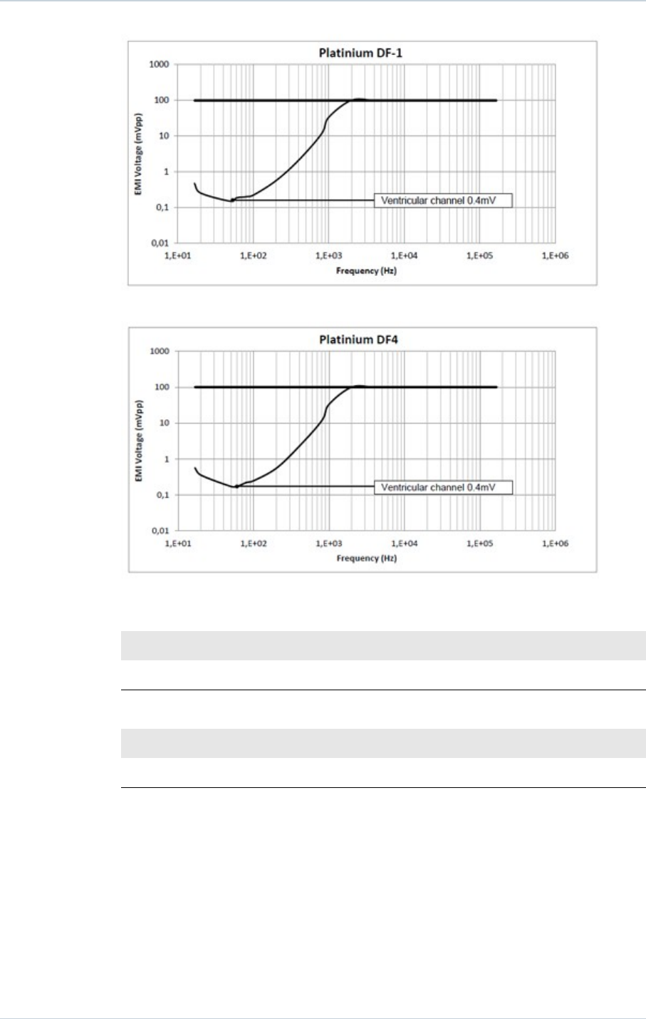
Per Clause 27.4 of Standard EN 45502-2-2, detection in the presence of electromagnetic
fields is characterized as follows:
─Differential mode:
For DF-1 models:
34 SORIN – PLATINIUM VR – U461A
15. SPECIAL MODES
For DF4 models:
─Common mode rejection ratio:
For DF-1 Models:
16.6 Hz 50 Hz 60 Hz
Ventricular channel ≥68 dB ≥68 dB ≥68 dB
For DF4 Models:
16.6 Hz 50 Hz 60 Hz
Ventricular channel ≥68 dB ≥68 dB ≥68dB
For ventricular sensitivity settings below 0.6mV, the ICD may detect noise lower than the
level specified in clause 27.5.1 of standard EN 45502-2-2 for frequencies below 200 Hz.
15.5. PROTECTION AGAINST SHORT-CIRCUITS
The defibrillator can undergo a short-circuit if the anode and cathode are not adequately
separated.
In this case, the shock is aborted to prevent damaging the defibrillator and a warning will
indicate that a short circuit (shock impedance < 20 ohms) was detected during the last
shock.
SORIN – PLATINIUM VR – U461A 35

16. MAIN FUNCTIONS
16. MAIN FUNCTIONS
16.1. AUTOMATIC LEAD MEASUREMENTS
Automatic pacing lead impedance measurement:
A lead impedance measurement is automatically performed on the lead every 6 hours.The
daily mean impedance is stored.
Automatic coil impedance measurement:
A continuity measurement is automatically performed on defibrillation coil(s) once per day.
The continuity is stored for each coil.
Automatic sensing measurement:
The amplitude of R waves are automatically measured at each cycle. Every 8.5 minutes, the
amplitude of the last 8 R detections are averaged and stored.
16.2. VENTRICULAR TACHYARRHYTHMIA MANAGEMENT
Arrhythmia discrimination algorithm Stability/Acceleration and
Stability+/Acceleration:
Stability/Acceleration is the algorithm used to discriminate sinus tachycardias (ST) and
supraventricular tachycardias (SVT) from ventricular tachycardias (VT).
Stability+/Acceleration is based on the Stability/Acceleration algorithm but additionally takes
into account the “AFdetect” discrimination criteria: the occurrence of a ‘long ventricular cycle’
characteristic for AF patients which is an additional arrhythmia classification criterion to
improve identification of atrial fibrillation and avoid inappropriate shocks.
Fast VT treatment:
Applies detection criteria on fast ventricular tachycardia that are different from those of the
VT zone, as well as different therapies. The fast VT zone is included in the VF zone: its
lower limit is determined by the programmed value for the VF zone and its upper limit by the
programmed value for the fast VT zone.
Polarity alternation on Max shock:
Reverses the programmed polarity of every second shock set at maximum energy. The
number, type, and energy of shocks is independently programmable by detection zone.
Defibrillation threshold (DFT):
Be aware that the changes in the patient’s condition, drug regimen, and other factors may
change the defibrillation threshold (DFT) which may result in non-conversion of the
arrhythmia post-operatively. Successful conversion of ventricular fibrillation or ventricular
tachycardia during arrhythmia conversion testing is no assurance that conversion will occur
post-operatively.
36 SORIN – PLATINIUM VR – U461A

16. MAIN FUNCTIONS
16.3. PACING
BTO (Brady Tachy Overlap):
Allows pacing in the slow VT zone, without affecting arrhythmia detection specificity.
Post-shock mode:
After any automatic shock therapy, the post-shock mode makes it possible to apply different
pacing parameters.
16.4. SENSING
Automatic Refractory Periods:
Optimize sensing and make the implant programming easier. These periods are composed
of a minimal Refractory Period and a triggerable Refractory Period. The duration of the
refractory periods lengthens automatically as needed.
Protection against noise:
Allows the distinction between ventricular noise and ventricular fibrillation. If the device
senses ventricular noise, the ventricular sensitivity is decreased until noise is no longer
detected. Ventricular pacing can be inhibited to avoid a potential paced T-wave.
Automatic sensitivity control:
Optimizes arrhythmia detection and avoids late detection of T-waves and over-detection of
wide QRS waves. The device automatically adjusts the sensitivities based on the ventricular
sensing amplitude. In case of arrhythmia suspicion or after a paced event, the programmed
ventricular sensitivity will be applied. The minimum ventricular sensitivity threshold is 0.4 mV
(minimum programmable value).
16.5. FOLLOW-UP FUNCTION
Storage of memory data:
AIDA+ (Automatic Interpretation for Diagnosis Assistance) software provides access up to 6
months of patient follow-up with day by day data collection, or up to 24 hours with hourly
data collection. Episodes of ventricular tachyarrhythmia are recorded with one
programmable EGM channel which can be selected, in addition to RV EGM.
Alerts / Warnings:
The device routinely performs security self-checks and technical measurements to ensure
system integrity. When system integrity is found to be at risk outside a follow-up, alerts are
stored in the device memory. When system integrity is found to be at risk during a follow-up,
the information is managed by a warning (pop-up message) to immediately notify the user.
For example, the following types of event can trigger a warning or an alert: technical
problem during a shock, lead impedance or shock continuity measurements out-of-range,
battery depletion, …
16.6. REMOTE MONITORING FUNCTION
Remote monitoring enables the automatic remote transmission of implant data to the
physician thanks to the wireless Radio Frequency (RF) communication ability of the implant
in order to provide a comprehensive report to the physician about device functioning and
patient cardiac status without having the patient physically in the clinic.
SORIN – PLATINIUM VR – U461A 37

16. MAIN FUNCTIONS
The data is transmitted from the implant to the SMARTVIEW monitor, a small transmitter
placed in the patient's home.
Implant data are first transmitted to the SMARTVIEW monitor via RF. Data are then rooted
through the phone line or via GPRS to an internet website. This website is responsible for
transforming the implant data into a comprehensive report that can be consulted by the
physician.
16.6.1. SMARTVIEW Monitor
The SMARTVIEW monitor is a small device equipped with an RF transmission module to
communicate with the implant and a modem to export data through the internet.
The SMARTVIEW monitor is delivered to the patient who has to install it at home. Preferably
the SMARTVIEW monitor will be placed on the nightstand of the patient, as close as
possible to the side of the bed where the patient usually sleeps. The SMARTVIEW monitor
connects to the phone line of the patient and the power plug. Regular transmissions are
done during the night when the patient is asleep next to the SMARTVIEW monitor without
any intervention from the patient.
16.6.2. Transmission trigger
There are 3 different triggers for a remote transmission:
─the remote follow-up transmission is scheduled by the physician to occur regularly
(according to the programming).
─the alert transmission will take place when the implant has recorded an abnormal
event. The list of abnormal event is available in a following paragraph. Alert conditions
are checked daily.
─the on-demand follow-up transmission is triggered by the patient himself through the
use of a specific button on the SMARTVIEW monitor.
16.6.3. Data transmitted
The data transmitted are identical to the data available during a standard interrogation with
the dedicated programmer. All counters, histograms, IEGMs and diagnosis available in the
device are transmitted containing (not exhaustive list):
─programmed parameters
─information on patient and system implanted
─battery status
─lead status (brady leads and defibrillation coils)
─pacing counters and mean heart rate (brady)
─ventricular arrhythmia counters and episodes
─ventricular therapy counters
Data are presented in the form of 2 reports to the physician: the first one contains a
summary of major counters, histograms, warnings and diagnosis. The second one presents
the most important IEGM episodes automatically selected based on the degree of severity
for the patient.
16.6.4. User website
On the website, the physician is able to:
38 SORIN – PLATINIUM VR – U461A

16. MAIN FUNCTIONS
─consult and schedule the remote follow-ups of their patient
─configure additional ways of being notified of alerts (for instance by SMS, fax or e-mail)
─consult, print and export patient reports
16.6.5. Alert system
The following set of alert trigger can be independently programmed ON/OFF by the
physician using the dedicated programmer and can trigger an alert transmission:
─Low or high impedance
─Abnormal coil impedance (shock lead)
─Low or High shock impedance
─Inefficient high energy shock
─All shocks programmed OFF
─Shock treated VT/VF
─ATP treated VT/VF
─Suspicion of noise on the V lead
The following set of alert trigger (system alerts) cannot be deactivated when the Alerts are
programmed “On” and can trigger an alert transmission:
─Battery depletion – RRT
─Device reset
─Excessive charge time (>25s)
─System integrity
SORIN – PLATINIUM VR – U461A 39
WARNING: The use of remote monitoring does not replace regular follow-up. Therefore,
when using remote monitoring, the time period between follow-ups visits may not be
extended.

17. PATIENT FOLLOW-UP
17. PATIENT FOLLOW-UP
17.1. FOLLOW-UP RECOMMENDATIONS
Before the patient is discharged and at each subsequent follow-up visit, it is advisable to:
─check the occurrence of system warnings
─check the battery status,
─check the integrity of the pacing and defibrillation leads,
─check for proper sensing (sensitivity) and pacing ; set the pacing amplitude to twice the
pacing threshold,
─interrogate the implant memories (AIDA+),
─check the efficacy of the therapies delivered,
─keep a printout of programmed parameters, test results, and memory data,
─reset the memory data and statistics.
These operations should be performed by medical personnel in an appropriate care unit,
with resuscitation equipment present.
It is recommended that a routine follow-up examination be done one month after discharge,
and then every three months until the device nears the replacement date.
Refer to the online help for a description of displayed warning, and the necessity to contact
Sorin for an evaluation.
Implant software upgrade:
In case a new implant software is downloaded in the device memory through the
programmer, a warning message could be displayed by the programmer to inform the user
and give the correct instructions to follow.
17.2. HOLTER FUNCTION
The Holter records markers and EGM on RV and on 1 programmable channel: RV coil –
Can / SVC coil – Can / RV coil - SVC coil / RV tip – Can / RV ring – Can
─Up to 10 episodes and 5 min EGM on significant events: lead impedance out of range.
─Up to 16 tachyarrhythmia episodes as well as the therapy history.
Stored Tachyarrythmia Episodes:
PLATINIUM VR stores up to 16 episodes (VF, VT, Slow VT, SVT/ST, non-sustained) with a
total of 25.6 min of high resolution EGM.
40 SORIN – PLATINIUM VR – U461A
NOTES:
If the last reforming, charge or shock occurred during the week preceding the interrogation,
the last battery value may be still impacted by the event. One week post event, the battery
will recover its steady state value.
Automatic capacitor charging may affect communication between the device and the
programmer.

17. PATIENT FOLLOW-UP
For each episode four levels of details are presented:
─Tachogram
─Event log for the entire episode:
─"Arrhythmia Discrimination" analysis for each majority,
─Delivered therapies,
─Markers: Ventricular markers, sensed, paced and in relative refractory periods,
─EGM: onset and detection of the arrhythmia, on two therapies, and the return to slow
rhythm by recording electrogram.
Therapy history
For each arrhythmia detection, each therapy delivered (either automatically or during an
electrophysiological study) and at the end of each arrhythmia, PLATINIUM VR records the
type of majority rhythm, the number of ATP sequences delivered, the energy and the
number of shocks delivered.
17.3. RECOMMENDED REPLACEMENT TIME (RRT)
Recommended Replacement Time (RRT)(1) is controlled by: battery voltage equal to 2.62 V
± 0.01 V
Between the RRT and the EOS (End of Service)(2), PLATINIUM VR can still function for:
─14 months (100% pacing in VVI mode, 500 ohms, with as shipped settings), and deliver
15 shocks at 34 J or
─10,4 months (0% pacing, sensors OFF, one shock every 2 weeks) and deliver 21 shocks
at 34 J.
Once the Recommended Replacement Time (RRT) point has been reached, the device
operates normally, except that the charge time increases. Under normal conditions (and
without programmer use) the charge times are as follows:
Shock energy Charge time (sec)
BOS(3) 42 J 10 (± 2)
RRT 42 J 13 (± 3)
(1) Recommended Replacement Time (RRT) corresponds to Elective Replacement
Indicators (ERI) previously used.
(2) End of Service (EOS) corresponds to End of Life (EOL) previously used.
(3) Beginning of Service (BOS) corresponds to Beginning of Life (BOL) previously used.
17.4. EXPLANTATION
The defibrillator should be explanted in the following cases:
─The Recommended Replacement Time (RRT) point is reached
─Confirmed malfunction
─Burial of the patient (for environmental reasons, the local regulation may require the
explantation of the devices containing a battery supply)
SORIN – PLATINIUM VR – U461A 41
CAUTION: The defibrillator should be replaced as soon as the Recommended Replacement
Time (RRT) point is reached.

17. PATIENT FOLLOW-UP
─Cremation of the patient (the defibrillator may explode if placed in an incinerator)
The explanted defibrillator should not be reused in another patient.
All explanted defibrillators should be returned to Sorin, carefully cleaned of all traces of
contamination. Cleaning may be done by immersing them in an aqueous sodium
hypochlorite containing at least 1% chlorine, followed by rinsing copiously with water.
The defibrillator should be protected against mechanical impact and the temperature
variations that may occur during shipping.
Before explantation, it is advisable to:
─Print out all programmed parameters, statistics and Holter function report,
─Save Patient data on floppy disk or hard disk,
─Disable shock therapies (VT and VF) to avoid any risk of untimely shock.
17.5. DEFIBRILLATOR IDENTIFICATION
The defibrillator can be interrogated and programmed via telemetry, using the programming
head interfaced with the Sorin dedicated programmer.
Position the programming head over the telemetry antenna located in the upper part of the
device, in order to communicate effectively via telemetry (see diagram below).
The device can be non-invasively identified as follows:
1. Take an x-ray to identify the name of the manufacturer and model, printed on the device
(X-ray ID is SEA for PLATINIUM range).
2. Interrogate the device using the Sorin dedicated programmer. The model and serial
number of the device are automatically displayed. The first figure in the serial number
corresponds to the last figure in the year of manufacture.
42 SORIN – PLATINIUM VR – U461A
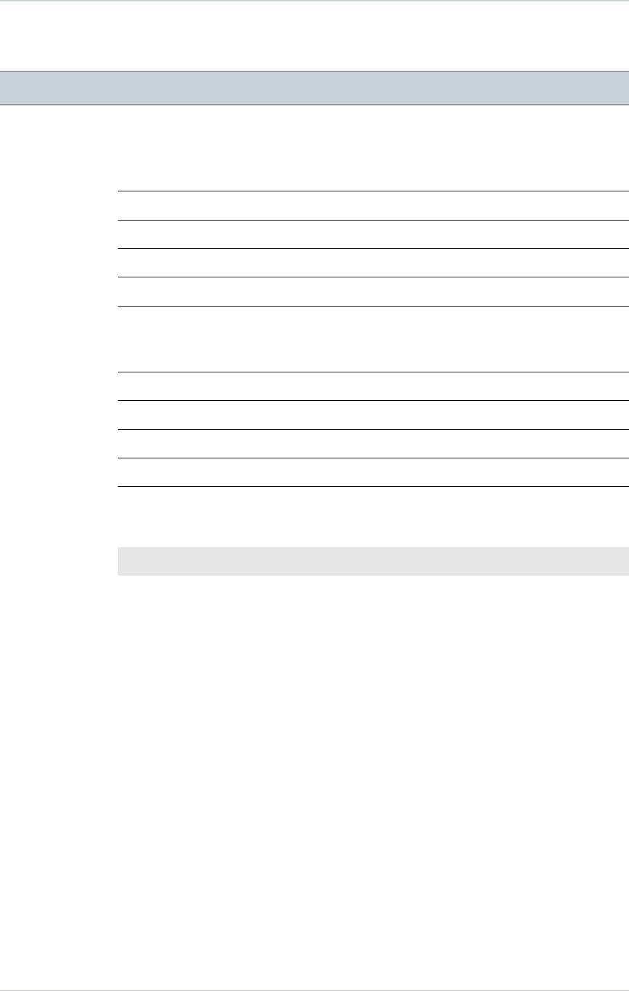
18. PHYSICAL CHARACTERISTICS
18. PHYSICAL CHARACTERISTICS
1210 MODEL:
Dimensions 73 x 54.3 x 11.1mm
Weight 85 g
Volume 33 cm3
Active surface area of casing 62.7cm2
Connector IS-1 bipolar, 2*DF-1.
1240 MODEL:
Dimensions 65.8 x 54.3 x 11.1 mm
Weight 84 g
Volume 31.2 cm3
Active surface area of casing 62.9cm2
Connector DF4.
18.1. MATERIALS USED
Active surface area of casing 99% pure titanium
Connectors Polyurethane* and silicone elastomer*
*Medical-grade materials that have undergone "in vitro" and "in vivo" qualifications.
SORIN – PLATINIUM VR – U461A 43
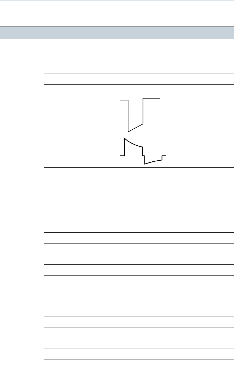
19. ELECTRICAL CHARACTERISTICS
19. ELECTRICAL CHARACTERISTICS
Ventricular input impedance 80 kilohms ± 30 %
D.C. capacitance 149 µF ± 8 %
Capacitor reformation No reformation required
Rate limit 192 ppm ± 10 ppm
Pacing waveform
Defibrillation waveform
19.1. TABLE OF DELIVERED SHOCK ENERGY AND VOLTAGE
The relationship between stored energies, maximum voltages and delivered energies (at 37
°C, 50 ohm load) for the minimum, low, mean and maximum programmed energy values is
as follows:
Stored energy (J) 0.5 10 20 34 42
V1 (Volt) 71 332 471 617 686
V2 (Volt) 35 167 235 309 342
Delivered E: Phase 1 (J) 0.32 6.94 14.0 23.8 29.6
Delivered E: Phase 2 (J) 0.08 1.75 3.4 6.0 7.4
Delivered E: Total (J) 0.4 8.7 17.4 30 37
Tolerances are 12% for voltage (25% at 0.5 J) and 30% for energy.
19.2. BATTERY
Manufacturer Greatbatch
Type Quasar High Rate (QHR)
Model GB 3070
Number of batteries 1
Total capacity 2192 mAh
44 SORIN – PLATINIUM VR – U461A

19. ELECTRICAL CHARACTERISTICS
Usable capacity Between BOS and RRT: 1530 mAh. Between BOS and EOS:
1910 mAh.
Voltage BOS: 3.24 V. RRT: 2.62 V. EOS: 2.5 V.
19.3. LONGEVITY
The longevities are calculated by taking into account 6 months storage with the following
conditions:
─Mode: VVI
─EGM:ON
─2 battery reformings per year (at 34J), replaced by shocks if any
─Remote monitoring: ON, daily check, 4 follow-ups and 5 full alert reports per year
─RF telemetry: ON, 45min at implantation + 15min at discharge + 15min for in-clinic
quarterly follow-ups
Longevity projection at 500 Ω pacing impedance:
Basic Rate (ppm) 60 60 60 60 60 40 60
V pacing (%) 100 100 1 15 15 6 0
Pacing amplitude (V) 3.5 3.5 3.5 4.5 2.5 2.5 -
Pulse width (ms) 0.35 0.35 0.35 0.50 0.35 0.35 -
Sensor OFF ON OFF OFF OFF OFF OFF
Max shocks (42J) per year 4 4 4 4 0 4 4
Longevity (years) 10.8 10.5 14 12.9 17.5 14.3 14.1
Longevity projection at 600 Ω pacing impedance:
Basic Rate (ppm) 60 60 60 60 60 40 60
V pacing (%) 100 100 1 15 15 6 0
Pacing amplitude (V) 3.5 3.5 3.5 4.5 2.5 2.5 -
Pulse width (ms) 0.35 0.35 0.35 0.50 0.35 0.35 -
Sensor OFF ON OFF OFF OFF OFF OFF
Max shocks (42J) per year 4 4 4 4 0 4 4
Longevity (years) 11.2 10.9 14.1 13.0 17.6 14.3 14.1
Longevity projection at 700 Ω pacing impedance:
SORIN – PLATINIUM VR – U461A 45
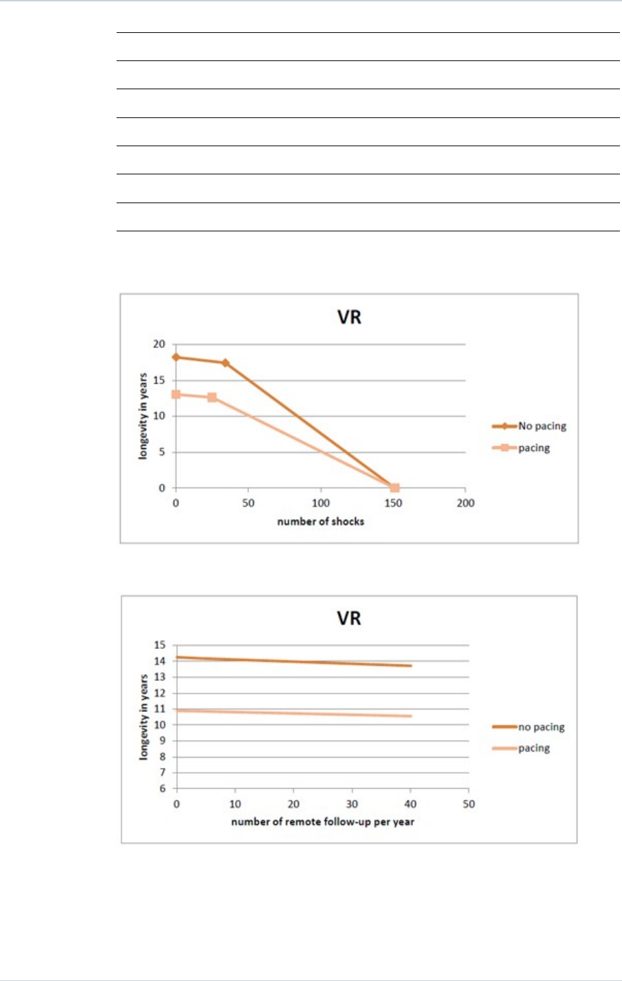
19. ELECTRICAL CHARACTERISTICS
Basic Rate (ppm) 60 60 60 60 60 40 60
V pacing (%) 100 100 1 15 15 6 0
Pacing amplitude (V) 3.5 3.5 3.5 4.5 2.5 2.5 -
Pulse width (ms) 0.35 0.35 0.35 0.50 0.35 0.35 -
Sensor OFF ON OFF OFF OFF OFF OFF
Max shocks (42J) per year 4 4 4 4 0 4 4
Longevity (years) 11.5 11.1 14.1 13.1 17.7 14.3 14.1
1h of additional RF programming session reduces the device longevity from 1 to 2 weeks
depending on the device functioning mode (no pacing, 100% pacing). The mean longevity
as a function of shocks delivered at maximum energy, with and without pacing, is as follows:
The mean longevity as a function of yearly remote follow-ups1, with and without pacing, is as
follows:
1. An excessive number of remote follow-ups can have a non-negligible impact on device
longevity.
46 SORIN – PLATINIUM VR – U461A
20. PROGRAMMABLE PARAMETERS
20. PROGRAMMABLE PARAMETERS
Measured at 37 °C under a 500 ohm load
Legend:
Value in bold: "as shipped" value
Underlined value: nominal value
20.1. ANTIBRADYCARDIA PACING
Basic parameters Values
Mode VVI-VVIR
Basic rate (ppm) (1) From 30 to 90 by steps of 5 ; 60 (± 4 %)
Maximum rate (ppm) From 100 to 145 by steps of 5 ; 120 (± 6 %)
Rate hysteresis (%) 0-5-10-20-35 (± 18 ms)
(1) The corresponding periods are (in ms): 2000-1714-1500-1333-1200-1091-1000-923-857-800-750-
706-667 ms.
Special features Values
Rate smoothing OFF-Very slow-Slow-Medium-Fast
Physical activity Very low-Low-Medium-High-Very high
Pacing/Sensing Values
Ventricular sensitivity (mV) (1) From 0.4 to 4 by steps of 0.2 ; 0.4 (± 50 %)
Ventricular amplitude (V) (2) 1-1.5-2-2.5-3-3.5-4-4.5-5-6 (± 20 %)
Ventricular pulse width (ms) 0.12-0.25-0.35-0.5-0.6-0.75-0.85-1 (± 10 %)
(1) Values are measured using a positive and negative triangular signal of 2/13 ms.
(2) The correlation between the programmed amplitudes, the stored amplitudes and the mid-pulse
delivered amplitudes under a 500 ohm load are given in the following table:
Programmed amplitude (V) Stored amplitude (V) Mid-pulse delivered amplitude
(V)
1 1,11 0,94
1,5 1,63 1,38
2 2,1 1,78
2,5 2,6 2,2
3 3,15 2,67
SORIN – PLATINIUM VR – U461A 47

20. PROGRAMMABLE PARAMETERS
3.5 3,65 3,09
4 4,2 3,55
4,5 4,69 3,97
5 5,25 4,44
6 6,3 5,33
Post-shock mode Values
Mode OFF-VVI
Duration 10s-20s-30s-1min-2min-3min-4min-5min
Basic rate (ppm) From 50 to 90 by steps of 5 ; 60 (± 4 %)
V amplitude (V) 1-1.5-2-2.5-3-3.5-4-4.5-5-6 (± 20 %)
V pulse width (ms) 0.12-0.25-0.35-0.5-0.6-0.75-0.85-1 (± 10 %)
Sensitivity margins Values
Ventricular post pacing margin (mV) From 0 to 2 by steps of 0.2 ; 0.8
Response to noise Values
Automatic sensitivity on noise ON-OFF
V pacing on noise ON-OFF
48 SORIN – PLATINIUM VR – U461A
20. PROGRAMMABLE PARAMETERS
20.2. VENTRICULAR TACHYARRHYTHMIA DETECTION
Therapy zones Values
Slow VT detection zone Slow VT ON-Slow VT OFF
VT detection zone VT ON-VT OFF
Fast VT / VF detection zone Fast VT+VF ON-VF ON
Slow VT rate (lower limit) (ppm) From 100 to 200 by steps of 5 ; 190
VT rate (lower limit) (ppm) 130-135-140-145-150-155-160-165-170-175-180-185-190-
195-200-210-220-230
VF rate (lower limit) (ppm) 150-155-160-165-170-175-180-185-190-195-200-210-220-
230-240
Fast VT rate (upper limit) (ppm) 155-160-165-170-175-180-185-190-195-200-210-220-230-
240-255
Slow VT persistence (cycles) 4-6-8-12-16-20-30-50-100-200
VT persistence (cycles) 4-6-8-12-16-20-30-50-100-200
VF persistence (cycles) From 4 to 20 by steps of 1 ; 6
Detection criteria Values
Slow VT and VT detection criteria Rate Only-Stability-Stability+-Stability/Acc-Stability+/Acc
Fast VT detection criteria Rate+Stability-Rate Only
Majority: (X/Y), Y (cycles) 8-12-16
Majority: (X/Y), X (%) 65-70-75-80-90-95-100
Window of RR stability for Slow VT
and VT (ms)
30-45-65-80-95-110-125
Window of RR stability for fast VT
(ms)
30-45-65
Acceleration (%) 6-13-19-25-31-38-44-50
Long cycle persistence extension
(cycles)
From 0 to 16 by steps of 1 ; 10
Long cycle gap (ms) 15-30-45-65-80-95-110-125-140-155-170-190-205
SORIN – PLATINIUM VR – U461A 49
20. PROGRAMMABLE PARAMETERS
20.3. VENTRICULAR TACHYARRHYTHMIA THERAPIES
Common parameters Values
Enable ATP therapy Yes-No
Enable shock therapy Yes-No
Polarity alternation (42J) Yes-No
Atrial coil (SVC) present Yes-No
Active case Yes-No
Shock configuration (+ --> -) Case to RV-SVC to RV-Case + SVC to RV-RV to Case-RV to
SVC-RV to Case + SVC
SVC exclusion (shock < 15J) Yes-No
20.3.1. Therapy parameters in slow VT zone
ATP 1 program Values
ATP program OFF-Burst-Burst+Scan-Ramp-Ramp+Scan
Number of sequences 1-2-3-4-5-6-7-8-9-10-11-12-13-14-15
Cycles in first sequence 1-2-3-4-5-6-7-8-9-10-11-12-13-14-15
Cycles added per sequence 0-1-2-3-4-5-6-7-8-9-10-11-12-13-14-15
Coupling interval (%) 50-55-60-65-70-75-80-85-90-95
Ramp decrement (per cycle) (ms) 0-4-8-12-16-20-30-40-50-60
Scan decrement (per sequence) (ms) 0-4-8-12-16-20-30-40-50-60
Time limit (min) 0.5-1-1.5-2-2.5-3-3.5-4
Minimum cycle length (ms) 95-110-125-140-155-170-190-205-220-235-250-265-280-
295-310
50 SORIN – PLATINIUM VR – U461A
20. PROGRAMMABLE PARAMETERS
ATP 2 program Values
ATP program OFF-Burst-Burst+Scan-Ramp-Ramp+Scan
Number of sequences 1-2-3-4-5-6-7-8-9-10-11-12-13-14-15
Cycles in first sequence 1-2-3-4-5-6-7-8-9-10-11-12-13-14-15
Cycles added per sequence 0-1-2-3-4-5-6-7-8-9-10-11-12-13-14-15
Coupling interval (%) 50-55-60-65-70-75-80-85-90-95
Ramp decrement (per cycle) (ms) 0-4-8-12-16-20-30-40-50-60
Scan decrement (per sequence) (ms) 0-4-8-12-16-20-30-40-50-60
Time limit (min) 0.5-1-1.5-2-2.5-3-3.5-4
Minimum cycle length (ms) 95-110-125-140-155-170-190-205-220-235-250-265-280-
295-310
Shock program Values
Shock 1 (J) OFF-0.5-0.8-1-1.3-1.5-2-2.5-3-3.5-4-5-6-7-8-9-
10-12-14-16-18-20-22-24-26-28-30-32-34-42
Shock 2 (J) OFF-0.5-0.8-1-1.3-1.5-2-2.5-3-3.5-4-5-6-7-8-9-
10-12-14-16-18-20-22-24-26-28-30-32-34-42
Number of Max. Shock (42 J) OFF-1-2-3-4
20.3.2. Therapy parameters in VT zone
ATP 1 program Values
ATP program OFF-Burst-Burst+Scan-Ramp-Ramp+Scan
Number of sequences 1-2-3-4-5-6-7-8-9-10-11-12-13-14-15
Cycles in first sequence 1-2-3-4-5-6-7-8-9-10-11-12-13-14-15
Cycles added per sequence 0-1-2-3-4-5-6-7-8-9-10-11-12-13-14-15
Coupling interval (%) 50-55-60-65-70-75-80-85-90-95
Ramp decrement (per cycle) (ms) 0-4-8-12-16-20-30-40-50-60
Scan decrement (per sequence) (ms) 0-4-8-12-16-20-30-40-50-60
Time limit (min) 0.5-1-1.5-2-2.5-3-3.5-4
Minimum cycle length (ms) 95-110-125-140-155-170-190-205-220-235-250-265-280-
295-310
SORIN – PLATINIUM VR – U461A 51
20. PROGRAMMABLE PARAMETERS
ATP 2 program Values
ATP program OFF-Burst-Burst+Scan-Ramp-Ramp+Scan
Number of sequences 1-2-3-4-5-6-7-8-9-10-11-12-13-14-15
Cycles in first sequence 1-2-3-4-5-6-7-8-9-10-11-12-13-14-15
Cycles added per sequence 0-1-2-3-4-5-6-7-8-9-10-11-12-13-14-15
Coupling interval (%) 50-55-60-65-70-75-80-85-90-95
Ramp decrement (per cycle) (ms) 0-4-8-12-16-20-30-40-50-60
Scan decrement (per sequence) (ms) 0-4-8-12-16-20-30-40-50-60
Time limit (min) 0.5-1-1.5-2-2.5-3-3.5-4
Minimum cycle length (ms) 95-110-125-140-155-170-190-205-220-235-250-265-280-
295-310
Shock program Values
Shock 1 (J) OFF-0.5-0.8-1-1.3-1.5-2-2.5-3-3.5-4-5-6-7-8-9-
10-12-14-16-18-20-22-24-26-28-30-32-34-42
Shock 2 (J) OFF-0.5-0.8-1-1.3-1.5-2-2.5-3-3.5-4-5-6-7-8-9-
10-12-14-16-18-20-22-24-26-28-30-32-34-42
Number of Max. Shock (42 J) OFF-1-2-3-4
20.3.3. Therapy parameters in fast VT / VF zone
ATP 1 program Values
ATP program OFF-Burst-Burst+Scan-Ramp-Ramp+Scan
Number of sequences 1-2-3-4-5-6-7-8-9-10-11-12-13-14-15
Cycles in first sequence 1-2-3-4-5-6-7-8-9-10-11-12-13-14-15
Cycles added per sequence 0-1-2-3-4-5-6-7-8-9-10-11-12-13-14-15
Coupling interval (%) 50-55-60-65-70-75-80-85-90-95
Ramp decrement (per cycle) (ms) 0-4-8-12-16-20-30-40-50-60
Scan decrement (per sequence) (ms) 0-4-8-12-16-20-30-40-50-60
Time limit 10s-20s-30s-1min-1.5min-2min
Minimum cycle length (ms) 95-110-125-140-155-170-190-205-220-235-250-265-280-
295-310
52 SORIN – PLATINIUM VR – U461A
20. PROGRAMMABLE PARAMETERS
Shock program Values
Shock 1 (J) OFF-0.5-0.8-1-1.3-1.5-2-2.5-3-3.5-4-5-6-7-8-9-
10-12-14-16-18-20-22-24-26-28-30-32-34-42
Shock 2 (J) OFF-0.5-0.8-1-1.3-1.5-2-2.5-3-3.5-4-5-6-7-8-9-
10-12-14-16-18-20-22-24-26-28-30-32-34-42
Number of Max. Shock (42 J) 1-2-3-4
20.4. REMOTE ALERTS AND WARNINGS
The device routinely performs security self-checks and technical measurements to ensure
system integrity. When system integrity is found to be at risk outside a follow-up, alerts are
stored in the device memory. When system integrity is found to be at risk during a follow-up,
the information is managed by a warning (pop-up message) to immediately notify the user.
For example, the following types of event can trigger a warning or an alert: technical
problem during a shock, pacing lead impedance or coil impedance measurements out-of-
range, battery depletion, etc. The Remote tab presents an overview of all the alerts
managed by the device.
General parameters Values
RF communication (1) ON-OFF
Alerts (1) ON-OFF
(1) RF and Remote alerts are turned on automatically if Shocks are programmed ON.
When Alerts are programmed "On", the following System Alerts are automatically activated:
─Battery depletion – RRT
─Device reset
─Excessive charge time (>25s)
─System integrity
Lead Alerts Values
Abnormal lead impedance ON-OFF
Abnormal lead low limit (Ohm) 200-250-300-350-400-450-500
Abnormal lead high limit (Ohm) 1500-1750-2000-2500-3000
Abnormal RV coil impedance ON-OFF
Abnormal SVC coil impedance ON-OFF
Abnormal Shock impedance (1) ON-OFF
(1) Normal impedance range [20 Ohm-200 Ohm]
Clinical status Values
V oversensing ON-OFF
SORIN – PLATINIUM VR – U461A 53

20. PROGRAMMABLE PARAMETERS
Therapy information Values
Shock disabled ON-OFF
Shocks delivered OFF-All shocks-Inefficient shock-Inefficient max shock
ATP delivered ON-OFF
54 SORIN – PLATINIUM VR – U461A

21. NON PROGRAMMABLE PARAMETERS
21. NON PROGRAMMABLE PARAMETERS
Ventricular refractory periods Values
Post ventricular sensing 95 ms (± 16 ms)
Post ventricular pacing 220 ms (± 4 ms)
Therapies Values
Waveform (1) Constant tilt (50% - 50%)
Stored energy for the Max. shock 42 J
Pacing amplitude during ATP
therapies
7 V (Actual value at 300 ms: 5.3 V )
(1) The device has 50% tilt in each phase thus delivers 94% of stored energy. Each phase is limited to
10 ms duration.
SORIN – PLATINIUM VR – U461A 55

22. LIMITED WARRANTY
22. LIMITED WARRANTY
The PLATINIUM implantable cardioverter defibrillator is the result of highly advanced
research and all components have been selected after exhaustive testing.
The terms of the limited warranty are available upon request from your Sorin representative
or on the CD-ROM of the package content.
56 SORIN – PLATINIUM VR – U461A

23. PATENTS
23. PATENTS
The PLATINIUM model described in this manual is covered by the following US patents:
5 713 928, 5 741 315, 5 776 164, 5 776 165, 5 818 703, 5 836 980, 5 868 793, 5 891 170, 5
891 184, 5 899 931, 5 931 856, 5 935 153, 5 954 660, 5 978 708, 6 181 968, 6 230 058, 6
236 111, 6 251 703, 6 256 206, 6 307 261, 6 337 996, 6 397 105, 6 408 209, 6 487 451, 6
487 452, 6 505 068, 6 532 238, 6 556 866, 6 604 002, 6 622 039, 6 625 491, 6 711 441, 6
738 665, 6 830 548, 6 889 080, 6 898 845, 6 912 421, 6 937 898, 6 975 905, 7 065 402, 7
072 716, 7 076 297, 7 113 826, 7 142 924, 7 164 946, 7 251 526, 7 366 566, 7 400 921, 7
400 922, 7 953 483, US8064992, US8043225, US7792582, US8798748, US7890168,
US8195293, US7966068, US8768464, US8874209, US8554313, US8214036, US8233981,
US8554319, US7966065, US8253279, US8874210, US8219193, US8391976, US8855764,
US8359096, US8494629, US8359091, US8489188, US8712526, US8862230, US8641436,
US8718765, US8798771, US8868170, US8678843 , US8694098, US8938286, US8874212.
SORIN – PLATINIUM VR – U461A 57
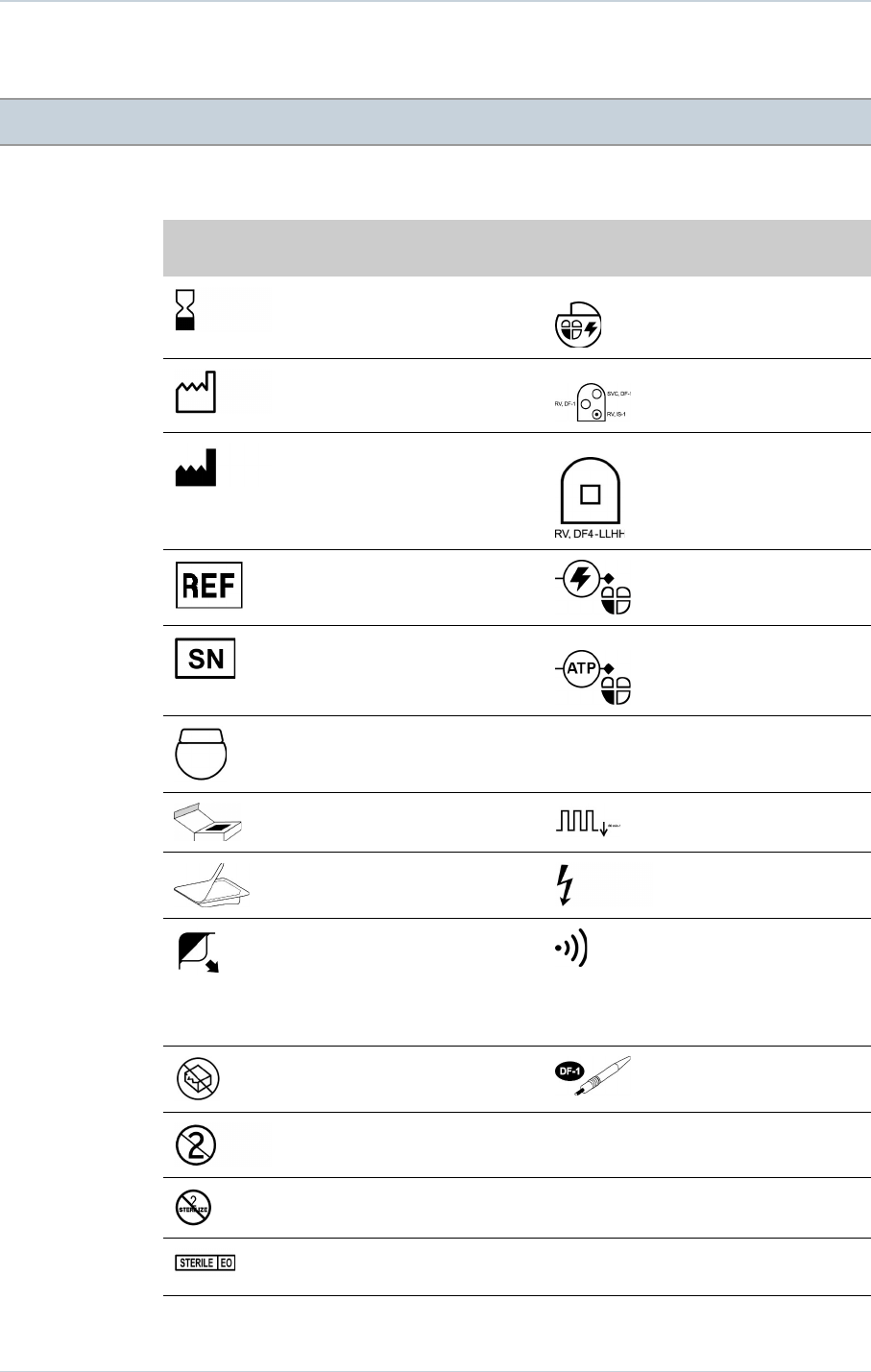
24. EXPLANATION OF SYMBOLS
24. EXPLANATION OF SYMBOLS
The symbols on product labelling have the following meaning:
General
symbols Explanation of symbols Defibrillator
symbols Explanation of symbols
Use by ICD (dual chamber, RV)
Date of manufacture VR DF-1 connectors
Manufacturer VR DF4 connectors
Catalogue number Shocks
Serial number ATP Anti-tachycardia pacing,
RV
Implantable device uncoated VVI As shipped mode
Package content Basic rate
Sterile package content High voltage
Open here Ready for wireless
interrogation and
programming by Orchestra
Plus programmer equipped
with ORCHESTRA PLUS
LINK accessory
Do not use if the package is
damaged
DF-1 defibrillating connector
insulating plug
Do not reuse
Do not resterilize
Sterilised using ethylene
oxide
58 SORIN – PLATINIUM VR – U461A
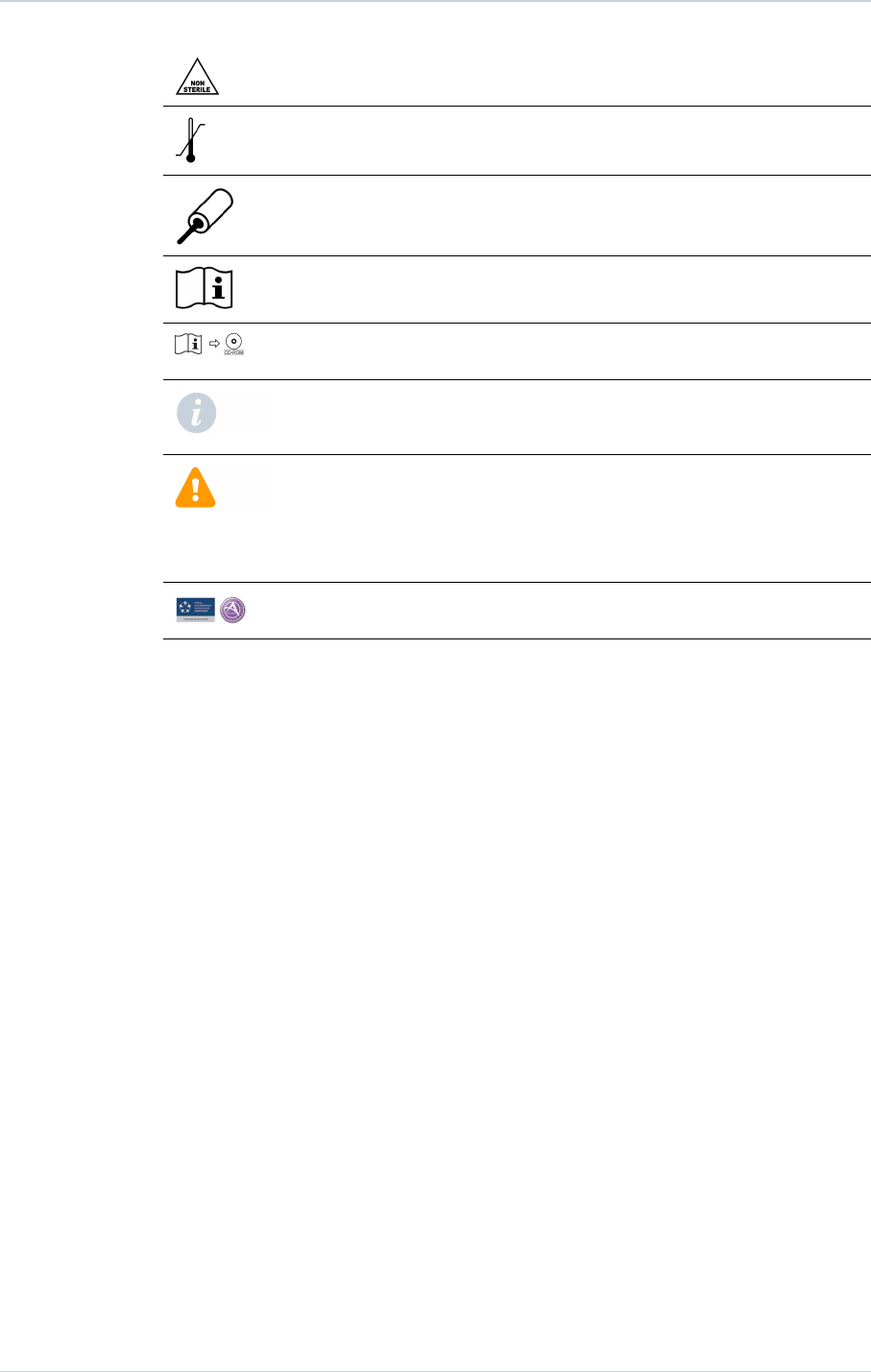
24. EXPLANATION OF SYMBOLS
Non sterile
Temperature limitation
Torque wrench
Consult instructions for use
Instructions for use in the
CD-ROM
This icon is used to call your
attention to a particularly
important point.
This icon alerts you to a
hazard that may result in
equipment damage or
personal injury. Carefully
read the instructions provided
with this icon.
Eucomed / Advamed Code of
Ethical Business Practice
Last revision date of this implant manual: 2015-03
SORIN – PLATINIUM VR – U461A 59
BACKCOVER
CAUTION: FEDERAL LAW RESTRICTS THIS DEVICE TO SALE BY OR ON THE ORDER OF A PHYSICIAN
2
0
1
5
-
0
3
U
4
6
1
A
© 2015 Sorin CRM SAS
2015-03
U461A