SOUTH NAVIGATION SOUTHGNSS-86 Survey Radio User Manual Manual
SOUTH NAVIGATION LIMITED Survey Radio Manual
Manual.pdf
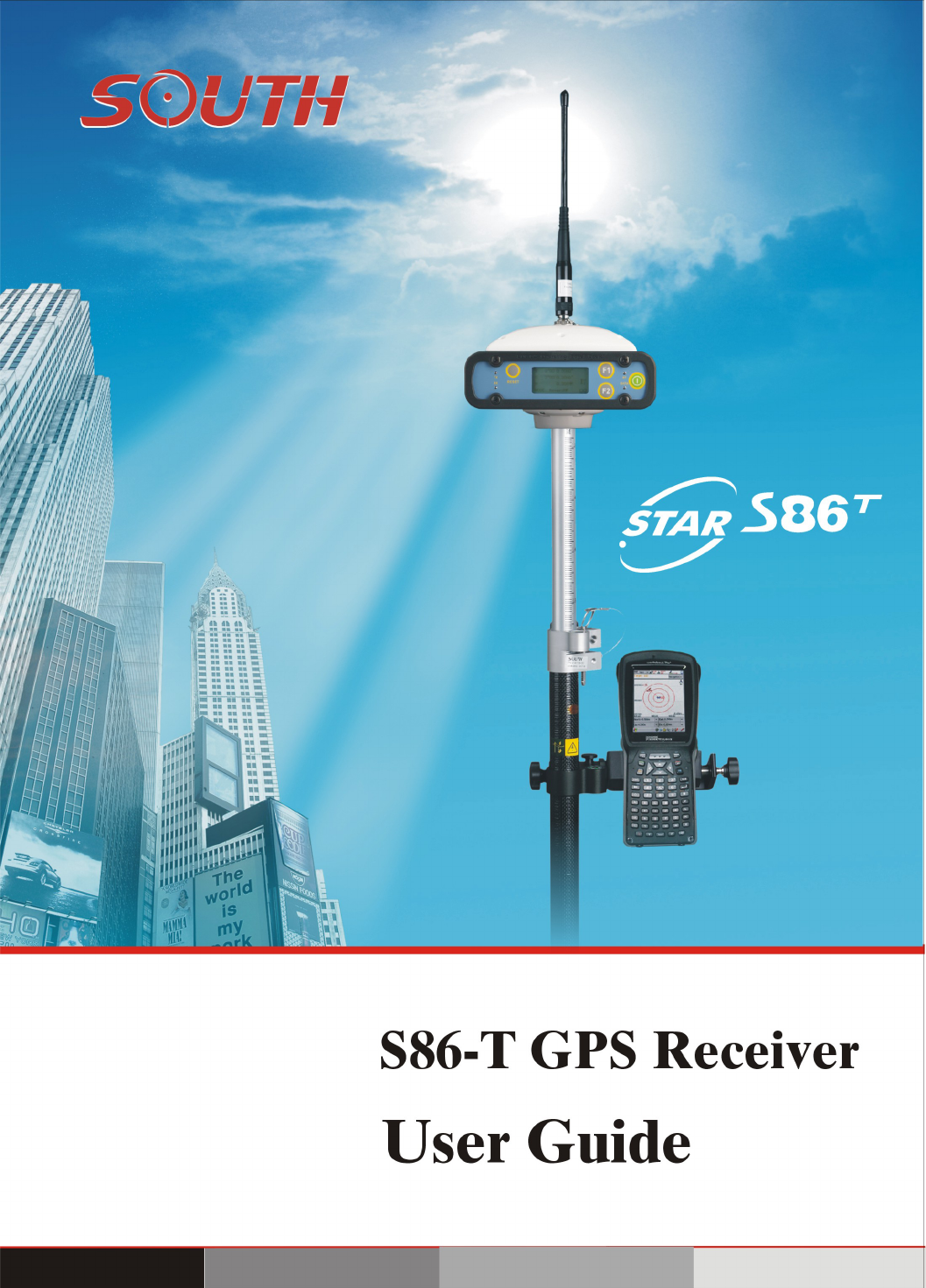

‐‐‐‐STARS86‐TGPSReceiver
UserManual
SOUTHCO.,Ltd.
www.southsurvey.com

2

3
CONTENTS
CONTENTS............................................................................................................3
Chapter1Introduction.........................................................................................1
1.1STARS86‐TGPSSystemSummary.............................................................1
1.2STARS86‐TGPSfeaturesandfunction......................................................1
1.3Technicalspecifications.............................................................................2
Chapter2TheHardwareofSTARS86‐T..............................................................5
2.1InterfaceofMainframe.............................................................................5
2.2Charging....................................................................................................
6
2.3CommunicationCable...............................................................................8
2.4Controller‐PCCable...................................................................................8
2.5Keysandindicatorlights............................................................................9
Chapter3AccessoriesofSTARS86‐T..................................................................12
3.1InstrumentCase......................................................................................12
3.2BatteryandchargerforController..........................................................13
3.3Transmitting/ReceivingantennaofDatalink..........................................14
3.4Cables......................................................................................................15
Chapter4Operation...........................................................................................18
4.1InstructionofSTARS86‐Tindicatorlight.................................................18
4.2Initializationinterface.............................................................................18
4.3Settingmode...........................................................................................18
4.4Collectionmode......................................................................................24
4.5Modulesetting........................................................................................28
Chapter5DataManageandTransfer.................................................................30

4
5.1Howtotransmitdata..............................................................................30
5.2Theuseofconfigurationfile....................................................................30
5.3Registerandupgrade..............................................................................31
Chapter6Statement..........................................................................................36
6.1FederalCommunicationCommissionInterferenceStatement...............36
6.2RadiationExposureStatement................................................................37

1
Chapter1Introduction
1.1STARS86‐TGPSSystemSummary
STARS86‐TcombinestheadvantagesofSOUTHseriesRTKproducts,followsadvancedtechnologyandthe
conceptofcontinuousinnovation,bringsthemostadvancedsurveyingsolutiontosurveyors,offershigher
precisionandmorereliability,makesthesurveyingworkeasierandsimpler.
1.2STARS86‐TGPSfeaturesandfunction
Thebuilt‐inradiomodulesintegrated in STAR S86Tsupportsa longer workdistancewiththemobilenetwork.
TheARMframeworkadoptedbySTAR86‐TintheCPUkernelenablestheoperatingspeedtoreach
400MHz,thusrealizingmulti‐taskingmainframe,fasterprocessingrate,andhigherrealtime.TheUSB
MASSSTORAGEstandardprotocolmakestheoperationfasterandmoreflexible.
STARS86‐Tmainfeatures:
1) Integrateddesign,highqualityscreen,andconvenientoperation.
2) Thecoretechnologyofdatalinkhasbeengreatlyimproved,basedontypicalRTKworkdistance,STAR
S86‐Trealizesthegoalofbuilt‐intransmitterradio,abandoningcablesandheavybatterycells.
3) Thebuilt‐inbatteriespackageintegratedinthemainframeensures12hoursworktime,andcanbe
chargedwithoutbeingtakenapart.
4) STARS86‐Tisintegratedwithbuiltinradiomodule, which can becustomizedbyusers.
5) STARS86‐TadoptsthenewestARM9CPU,whosespeedcanreach400MHzwithfasterprocessing
speed,biggermemorycapacity,andhigherrealtime.
6) TheOSisareal‐time,multi‐tasking,morepowerfulfunction,withthestandardcompactdiskfile
system;STARS86‐Tbecomesmorestable,reliable.Datamanagementandmaintenancebecomemore
convenient.
7) FilesystemadoptsUSBMASSSTORAGEstandardprotocol,whichenablesafasterdownloadingspeed.
8) All‐alloyfirmhousing,shockproof,dustproof,waterproof,morescientificstructure,muchsafer
shielding.

2
1.3Technicalspecifications
Channels:220
Satellitesignalstracked:
GPS:SimultaneousL1C/A,L2E,L2C,L5.
GLONASS:SimultaneousL1C/A,L1P,L2C/A(GLONASSMOnly),L2P.
SBAS:SimultaneousL1C/A,L5.
GIOVE‐A:SimultaneousL1BOC,E5A,E5B,E5AltBOC1.
GIOVE‐B:SimultaneousL1CBOC,E5A,E5B,E5AltBOC1.
COMPASS:(reserved):B1(QPSK),B1‐MBOC(6,1,1/11),B1‐2(QPSK),B2(QPSK),
B2‐BOC(10,5),B3(QPSK),B3BOC(15,2.5),L5(QPSK).
VerylownoiseGNSScarrierphasemeasurementswith<1mmprecisionina1Hzbandwidth.
Provenlowelevationtrackingtechnology.
Initializationtime:typically<8s.
Upto50Hzrawmeasurement&positionoutputs.
Signalrecapture:1sec.
RTKsignalinitializationtypically20sec.
Motherboard
InternalMemory:64Mb(25statichourswithfrequencyof1Hz)

3
Connectiondevices:
ConnectorsI/O:9‐pinsserialport(baudrateupto115.200kbps)and5‐pinsLEMOinterfaces.
MulticablewithUSBinterfaceforconnectingwithPC.
2.4GHzBluetoothdeviceclassII:maximumrangeis50m.
InternalRadio:maximumrange=10km.
Externalcell phonesupportforRTKandVRSoperation(optional).
Externalradio:frequency450MHz,emittingpowerandmaximumrangedependingonmodel,
maximumrange=22km.
Serialprotocols
Referenceoutputs:CMR+,CMRx,RTCM2.1,RTCM2.3,RTCM3.0,RTCM3.1.
Navigationoutputs:ASCII(NMEA‐0183GSV),AVR,RMC,HDT,VGK,VHD,ROT,GGK,GSA,ZDA,VTG,GST,
PJT,PJK,BPQ,GLL,GRS,GBS,GSOF.
Receiveraccuracy
Statichorizontalaccuracy=3mm±0.5ppm(RMS).
Staticverticalaccuracy=5mm±0.5ppm(RMS).
FixedRTKhorizontalaccuracy=8mm±1ppm(RMS).FixedRTKverticalaccuracy=15mm±1ppm
(RMS).
Codedifferentialpositioningaccuracy=0.45m(CEP).
StandAloneRTKpositioningaccuracy=1.5m(CEP).
SBASpositioningaccuracytypically<5m(3DRMS).
PowerSupply:
9toa15VDCexternalpowerinputwithover‐voltage.
Voltage:7.2V.
Workingtimeinstaticmode:typically6hours.
WorkingtimeinRTKrovermode:typically4hours.
ChargeTime:typically7hours.
Powerconsumption:<3.8W.
Remainingtimewithbatterylightblinking:1hour.

4
Physicalspecification:
Size:Height154mmx154mmx88mm.
Weight:1.2Kgwithinternalbattery,radiostandardUHFantenna.
Operatingtemperature:‐25°Cto60°C(‐13°Fto140°F)
Storagetemperature:‐55°Cto85°C(‐67°Fto185°F)
IP65
Waterproof:protectedfromtemporaryimmersiontodepthof1meterandfrom100%humidity.
Dustproof.
Shockresistance:designedtosurvivea2mfreedropontotheconcrete.
Vibrationresistance.
Note:Thespecificationscancomeuponlyifthelockedsatellitesarenotlessthan5,andmustfollowthe
recommendedprocedureinproductmanual.Severemulti‐patheffect,volatileionosphereenvironment
andHDOPvaluewillinfluencetheperformanceseverely.
5
Chapter2TheHardwareofSTARS86‐T
2.1InterfaceofMainframe
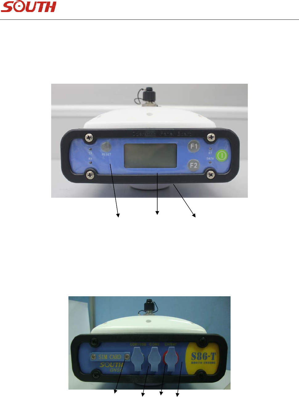
STARS86‐Tmainframeisasfollowingfigure2‐1,
(1)(2)(3)
Figure2‐1ScreenofMainframe
STARS86‐Treceiverisintegratedwithareceivingpart,adatacollectingpart,apowersupply,andaradio
module.WithhighqualityLCDscreen,all‐alloyhousing,and3proofdesign,STARS86‐Tcanwithstandthe
worstweather,roughestworkingconditions.
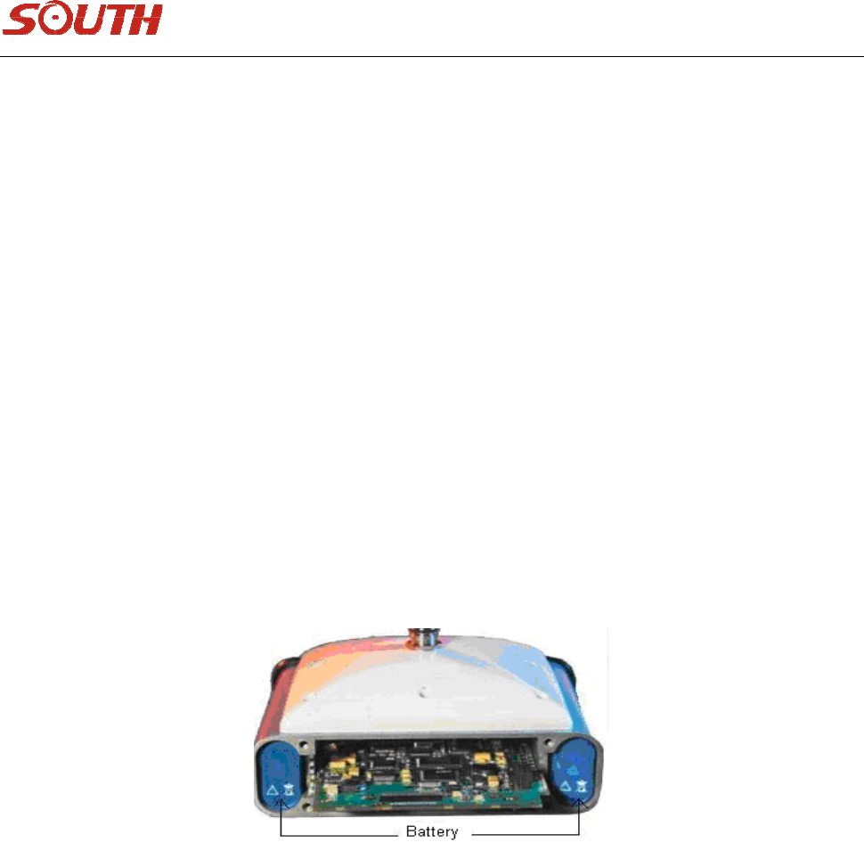
(4)(5)(6)(7)
Figure2‐2theportsideofSTARS86‐T
6
(1)‐‐‐‐‐‐‐‐‐‐‐OperationButton(referto3.1)
(2)‐‐‐‐‐‐‐‐‐‐‐LCDScreen(referto3.2)
(3)‐‐‐‐‐‐‐‐‐‐‐Slotforconnectingplummetandtribrach
(4)‐‐‐‐‐‐‐‐‐‐‐SlotforSIMCard
(5)‐‐‐‐‐‐‐‐‐‐‐Communicationport,7pins
(6)‐‐‐‐‐‐‐‐‐‐‐ExternalRadioport,5pins
(7)‐‐‐‐‐‐‐‐‐‐‐Charger&Externalpowersupplyport,4pins
Note:Com2isforexternalradio.Com1/USBisfordatatransferring.CH/BATisforchargingandexternal
powersupply.
2.2Charging
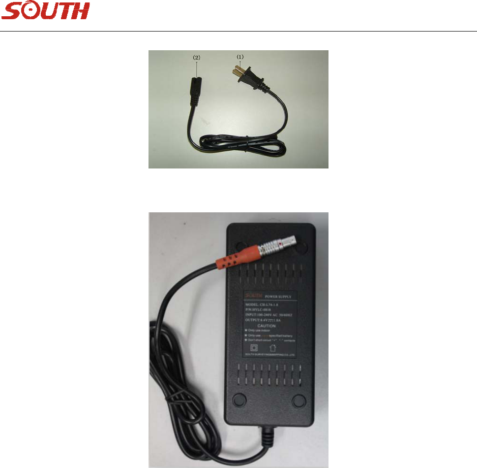
(1)STARS86‐Tbatterypackage
Thebatteriespackagesareembeddedonthetwoflanksofthemainframe.Afterbeingfully‐charged,the
built‐inradiocanworkcontinuouslyformorethan10hours.
Figure2‐3dualbatteriespackages
(2)ChargerofSTARS86‐T
ThechargerofSTARS86‐Tconsistsoftwoparts,ACadaptorcableandplug.Seeasfigure2‐4,2‐5.
7
Figure2‐4Powerplug
Figure2‐5ACAdaptorcable
①——220VACplug
②、③——Connectingpart
④——4pinsplug,insertittothechargingportonthemainframewhencharging.
⑤——Indicatorlightsofcharger.Whenthelight“CH1”、“CH2”turnsred,itmeansthebatteryisbeing
charged.Theindicator’sturninggreenmeansthebatteryisfullychargedordisconnectedwithmainframe.
Itdoesn’tmatterwhetheryouturnonthemainframeornotwhencharging.ourrecommendationisto
turnitoff.
8
2.3CommunicationCable
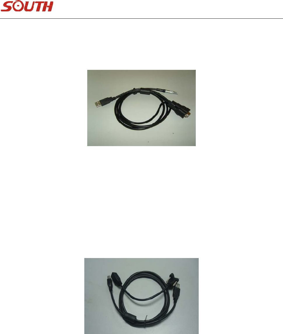
Datacommunicationcableisfordatadownloading,oneheadofitis7pinsport,theotherheadisUSB
plugandserialportplug,seeasfigure2‐6,
Figure2‐6Datacommunicationcable
Notice:whenyouinsertthe7pinsplugtothemainframe,makesuretheredpointontheplugisaligned
withtheredpointonthemainframe.Serialportplugisdesignedforspecialfunction.
2.4Controller‐PCCable
Controller‐PCcableisforthelinkbetweenPsioncontrollerandPC.It’scomposedbytwosections,oneis
connectedtocontroller,andtheotherisconnectedtoUSBportinPC.Seeasfigure2‐7.
Figure2‐7Controller‐PCcable
9
2.5Keysandindicatorlights
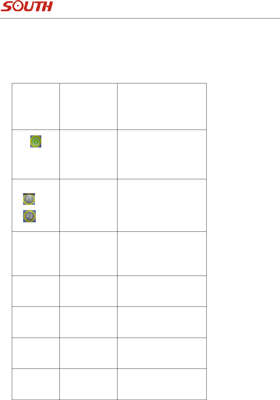
TXlightindicatesstatusofsignaltransmitting,RXlightindicatesstatusofsignalreceiving.BTlightis
Bluetoothlight,DATAlightisthedatatransmitting/receivinglight.ThekeysfromlefttorightareReset
key,twoFunctionkeysandPowerkey.Theindicatorinformationisasbelows.
FunctionFunctionorstatus
power
key
Poweron/off,
confirm,
modify
Poweron/offmainframe,
confirmedititems,select
modifieditems
&
Page
up/down,
return
Selectmodifieditemsor
returntopriormenus
ResetKey
Forceto
poweroff
Poweroffinspecial
condition,without
disturbingdatacollection
DATA
light
Dataindicator
light
blinkwhencollectingor
transmittingintervaltime
BTlight
Bluetooth
light
KeeponwhenBluetoothis
connected
RXlight
Receiving
signallight
Blinkwhenreceiving
intervaltime
TXlight
Transmitting
signallight
Blinkwhentransmitting
intervaltime

10
1. Staticmode
DATAlightblinkswhencollectingdataintervaltime.
2. Basemode(Radio)
TX,DATAlightsblinkwhentransmittingintervaltimesimultaneously.
3. Rovermode(Radio)
RXlightblinkswhentransmittingintervaltime.
DATAlightblinkswhentransmittingintervaltimeafterdifferentialsignalbeingreceived.
BTlightkeepsonshowsBluetoothisconnected.
4.Radio
(1)Built‐inradio(UHF)
STARS86‐Tisintegratedwitha0.5wor2wUHFbuilt‐intransmittingradio,withwhichthetypicalwork
distancecanreach2~5km,andnocableisneededinbasestation.Thebatterypackageinbasestation
enablesthebuilt‐inradiotoworkcontinuouslyfor10hours,meetingthedemandofsurveyors.

11
(2)Externalradio
WhenworkinginextensiveareawithSTARS86‐T,thebuilt‐inradiocannotcoverthelongdistance
betweenbaseandrover.thenyoucanchoosea2/5wor15/15wexternalradio.
Note:wheneveryoudebugtheradio,puttheradioantennaontopofit.Otherwise,theradiomightbe
broken.
(3)Module
STAR S86‐Tisintegrated built-in radiomodule, which canget accesstovariousCORS.
Itenormouslyextendsworkdistance,andimprovesaccuracyandreliability.
12
Chapter3AccessoriesofSTARS86‐T
3.1InstrumentCase
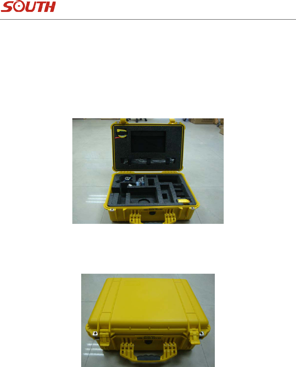
TheinstrumentcaseofSTARS86‐Tcontainstwolayers,theexternalishardblackcase,whichis
convenientforlongdistancetransport,theinnerisafoambox,withindividualsectionfordifferentparts
oftheinstrument.Seeasfigure3‐1.
Figure3‐1Instrumentcase
Thehardcaseisportable,durable,shockproof,andconvenienttoclean.Seeasfigure3‐2
Figure3‐2Hardcase
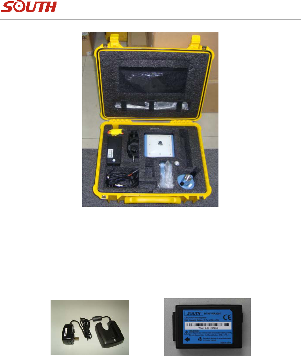
Thefoamboxisverylight,canholdmainframeandotheraccessories,youcanarrangethespacefreely.
Seeasfigure3‐3.
13
Figure3‐3Softbag
3.2BatteryandchargerforController
Aboutmainframebatteryandcharger,pleaserefertochapter2‐2.Aboutbatteryandchargerfor
controller,seeasfigure3‐4,3‐5.
Figure3‐4ChargerFigure3‐5Controllerbattery
14
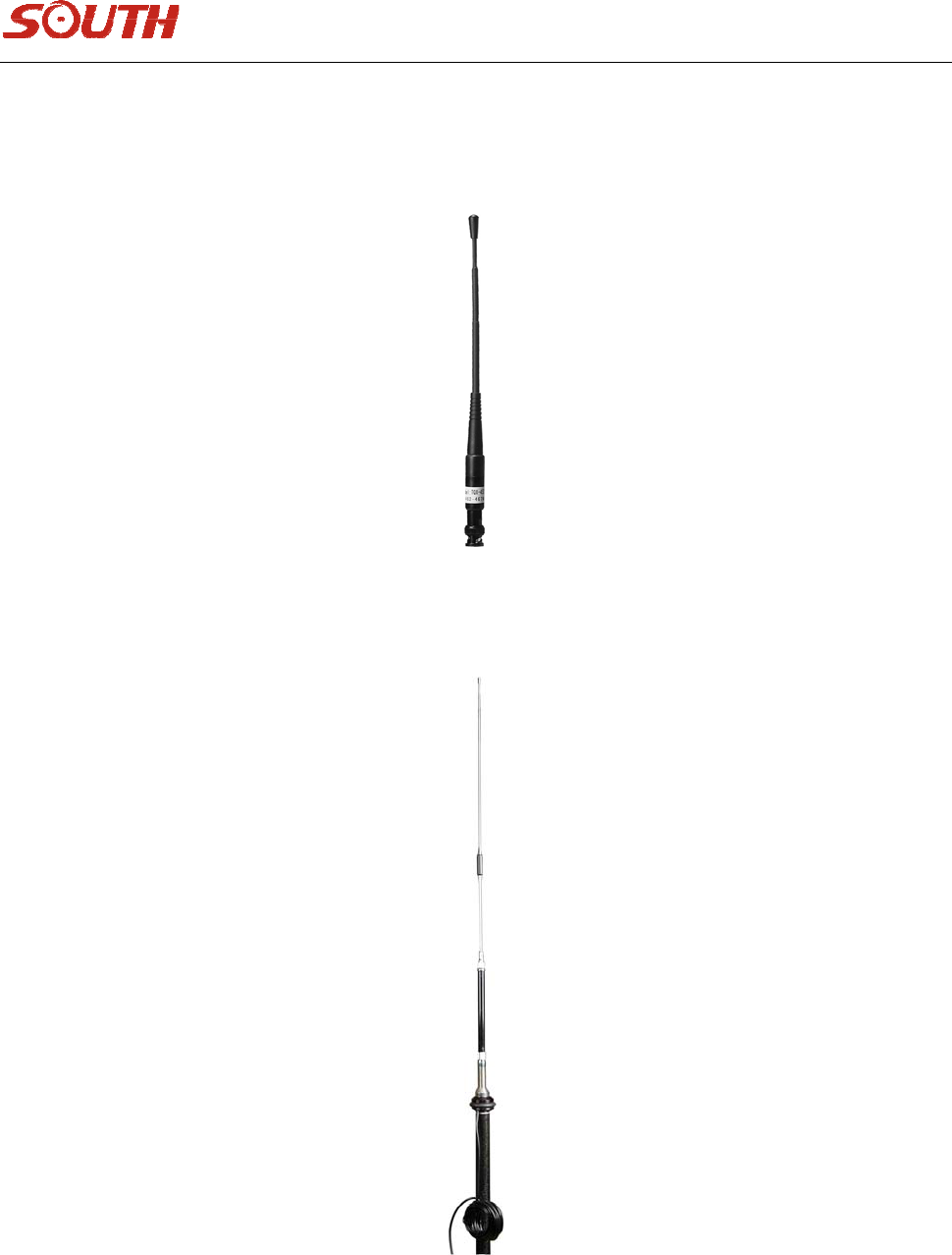
3.3Transmitting/ReceivingantennaofDatalink
STARS86‐Tadopts450MHzall‐directionantenna,whichcanworkbothastransmittingantennaand
receivingantenna.Seeasfigure3‐6.
Figure3‐6Receiving&TransmittingAntenna
Ifyouuseexternalradio,youneedanother5.5dball‐directionantenna,theappearanceisasfigure3‐7
Figure3‐7
15
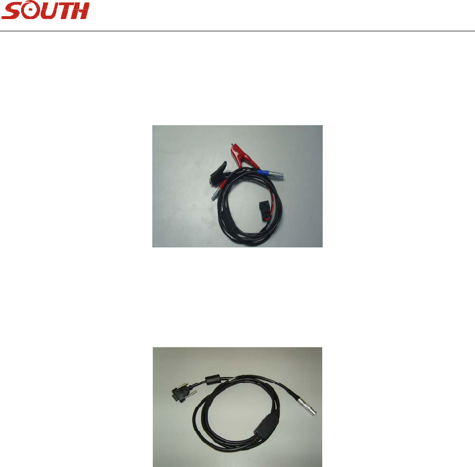
3.4Cables
1.Communicationcable
Communicationcableisforthelinkbetweenmainframeandexternalradio,alsoforpower
supplying,whichenablesalongerworkingtimeofthemainframeandexternalradio.Seeasfigure3‐8
Figure3‐8
2.Receiver‐controllercable
Receiver‐controllercableisforthelinkbetweenreceiverandcontroller,seeasfigure3‐9
Figure3‐9Receiver‐controllercable
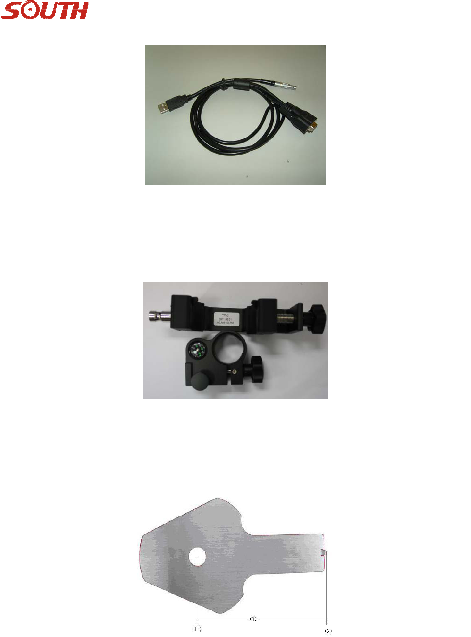
3.Multi‐communicationcable
Multi‐communicationcableisforthelinkbetweenreceivermainframeandPC.
Whichisusedforstaticdatadownloadingandfirmwareupdating.Seeasfigure3‐10
16
Figure3‐10Communicationcable
4.Otheraccessories
Bracketforcontroller
Figure3‐11Bracket
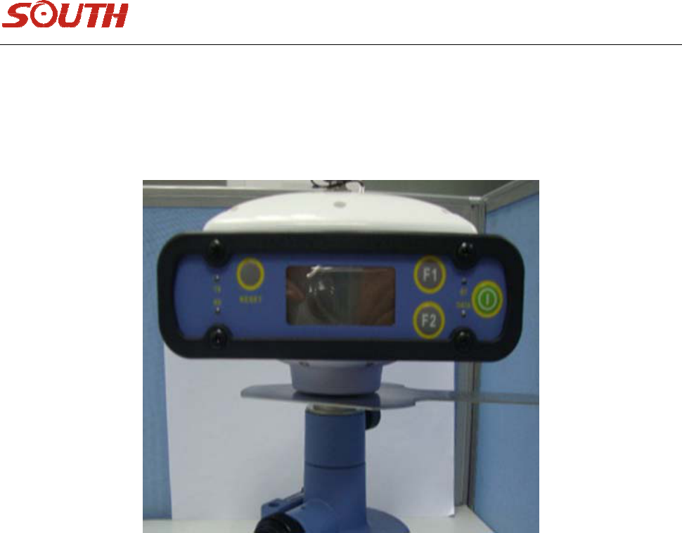
5.Himeasuringplate
helpmeasuringinstrumentheight,seeasfigure3‐12.
Figure3‐12Himeasuringplate
17
(1)—connectinghole
(2)—measuringedge
(3)—thedistanceisL=120mm
TheHImeasuringplateisplacedbetweenreceiverandconnector.Seeasfigure3‐13
Figure3‐13MeasureHeight
Afterplacinginstrument,usersneedtocheckoncebeforeandafteranobservationsession.Thewayisto
measurefromtheedgeofthemeasuringplatetothemarkpointcenteronground.Afterdatabeinginput
tothesoftware,itwillcalculatetherealheightoftheinstrument.
18
Chapter4Operation
4.1InstructionofSTARS86‐Tindicatorlight
1. inStaticmode
DATAindicatorlightblinkswhencollectingintervaltime.
2. inBasemode(Radio)
TX,DATAindicatorlightblinkwhentransmittingintervaltimesimultaneously.
3. inrovermode(Radio)
RXindicatorlightblinkwhentransmittingintervaltime.
DATAindicatorlightblinkwhentransmittingintervaltimeafterdifferentialdatabeingreceived.
BT(Bluetooth)indicatorlightkeepsonafterBluetoothbeingconnected.
4.2Initializationinterface
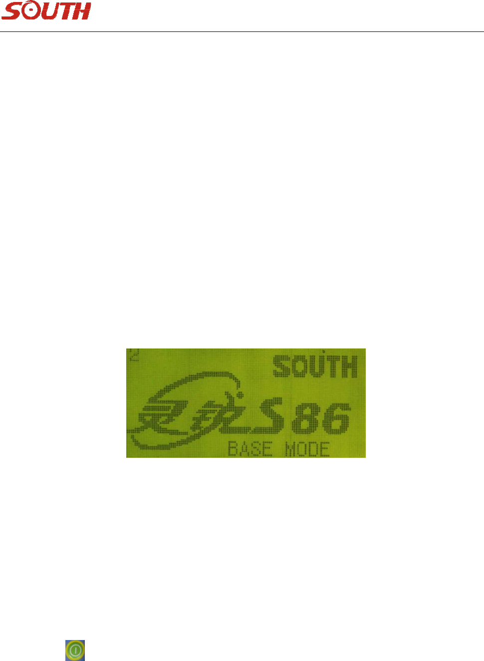
AfteryoupoweronSTARS86‐Treceiver,theinitializationinterfaceisasfollowingfigure,
Figure4‐1Initializationinterface
Youhavetwochoicesinthisinterface,settingmodeandcollectionmode.youcanclick“F2”toenter
settingmode,otherwise,itwillentercollectionmodeautomaticallyafterthecount‐down.
4.3Settingmode
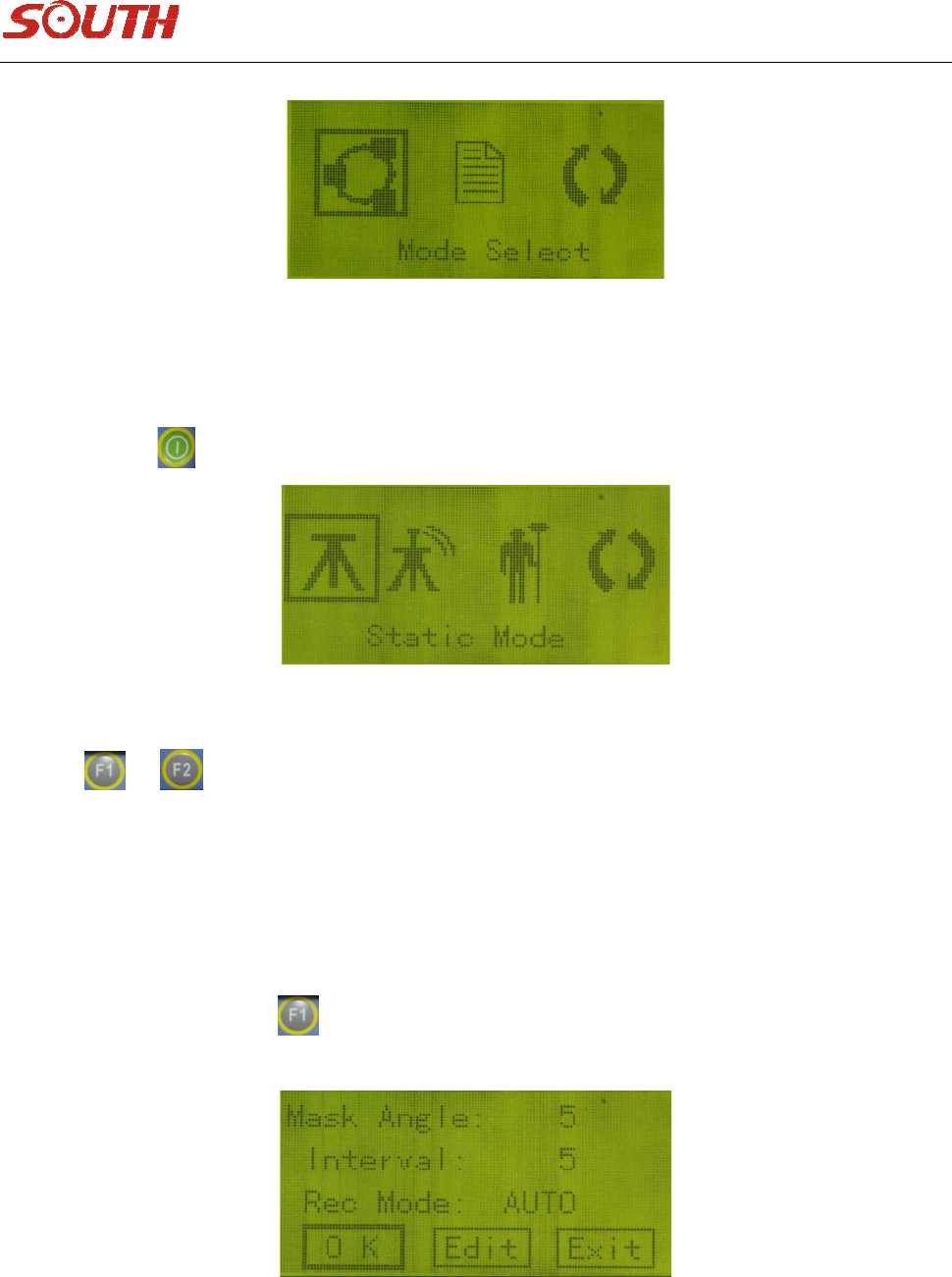
Thesettingmodeinterfaceincludestwomainmenusandaquitmenu.Thetwomainmenusaremode
selectmenuandsystemsettingmenu.youcanpressselectionbuttons(F1,F2)tochoosethemenu,
thenpresstoconfirm,seeasfigure4‐2.
19
Figure4‐2Settinginterface
4.3.1Modeselectmenu
Afterpressingbutton,youcanenterworkmodeselectinginterface,seeasfigure4‐3,
Figure4‐3
Therearethreekindsofworkmodestochoosefrom,staticmode,basemodeandrovermode.Youcan
pressorbuttontoselect,thelastmenuisforreturningtopriormenu.
(1) Parameterssettinginstaticmode
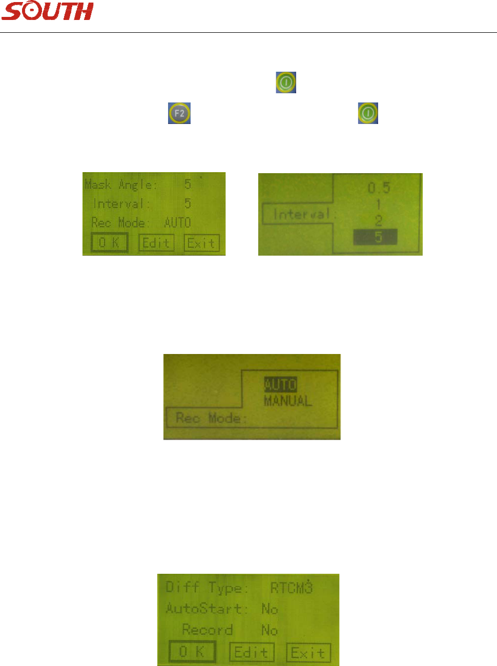
Afterenteringstaticmodeinterface,youcansetvariousparameters,suchasmaskangle,sampleinterval,
recordmode(therearetwoways,automaticandmanual.Whenyouselectautomaticway,thereceiver
willcollectstaticdataautomaticallyafterreceivingenoughsatellitesandgoodPDOPvalue.Ifyouselect
manualway,youneedpressbuttontostartafterreceivingenoughsatellitesandgoodPDOP),see
asfigure4‐4
Figure4‐4
20
Therearethreeoptionsatthebottomoftheinterface,OK,EditandExit.Ifyouwanttomodify
parameters,youcanmovethecursorto“Edit”,thenpressbuttontostartmodifyparameters.After
parametersbeingmodified,presstoreturnto“OK”,thenpressbuttontoconfirmit.Ifyou
don’twanttosavethemodifiedoperation,click“Exit”tocancelit.Thedetailedoperationsareasfollows,
Figure4‐5
Note:Thereare3specialintervalitems,0.1s,0.2sand0.5s,theGPSOEMmainboardareavailable,(extra
paymentneeded).
Figure4‐6
Note:You’dbettermakethesameparameterssettingwhenseveralSTARS86‐Tmainframesworking
together.
(2) Parameterssettinginbasemode
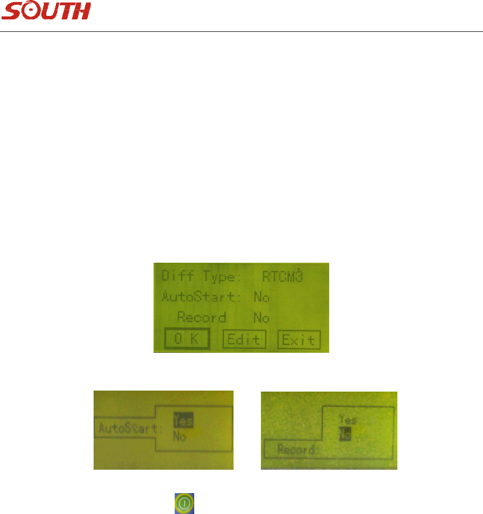
Afterenteringbasemodeinterface,youcansetparametersforbasemode,seeasfigure4‐7,
Figure4‐7
21
Thereare4optionsintheinterface,differentialtype,autostart,record.Thefunctionsoroptionsareas
belows:
Differentialtype:RTCA,CMR,RTCM2.x(includingRTCM2.0andRTCM2.3)
Interval:Transmittinginterval,Defaultsettingis1second.
Autostart:Twooptions,”Yes”or“No”,ifyouselect“Yes”,itmeansthebasestationwilltransmit
automaticallyafterreceivingenoughsatellitesandgoodPDOPvalue.Ifyouselect“No”,itmeansyou
wanttotransmitthebasestationmanuallyaftercheckingthesatellitesituation.“No”isthedefault
setting.
Record:WhenusingthereceiverinRTKmode,youcanstillrecordstaticdata,soiftheGPSorradiosignal
isnotgoodorinsometoughplaces,youcanstillrecordstaticdataandpost‐processittoobtainhighly
accurateresult.“No”isthedefaultsetting.Seeasfigure4‐8,4‐9,
Figure4‐8
Figure4‐9
Afteryoufinishthesesettings,presstoconfirm,youwillenterthesecondsettinginterface,
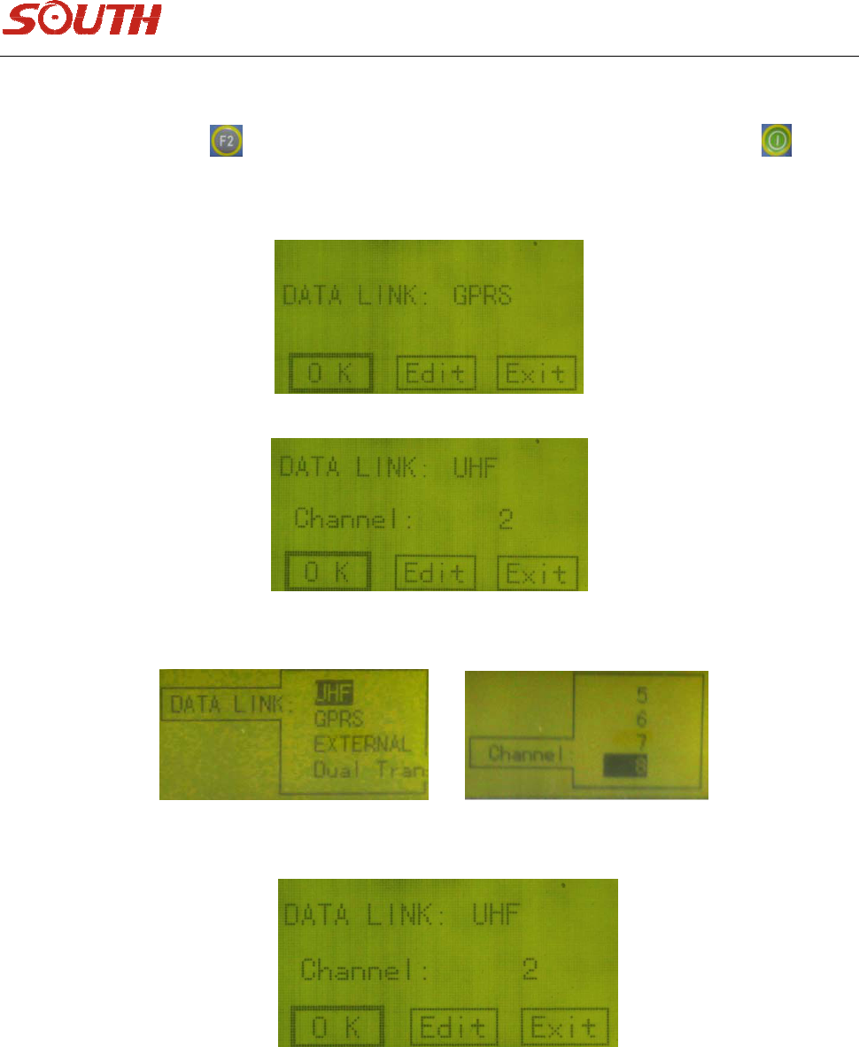
data‐linksetting.Thereare2optionsinthisinterface,datalink,andchannel.Theinstructionsareas
follows:
Datalink:4optionsforyoutochoosefrom,UHF,external,dual transmit.
UHF:forinternalradio,
External:forexternalradio
Dualtransmit:forexternalradiomodule workingsimultaneously.
22
Channel:Channelmeansradiochannels.Thereare8channelsinthisitem.
Settingsfinished,presstoreturntothemaininterface,movethecursorto“OK”andpressto
confirmyoursettings.thenthereceiverwillreturntotheinitializationinterface.Seeasfigure4‐10~4‐15
Figure4‐10
Figure4‐11
Figure4‐12Figure4‐14
Figure4‐13
(3)Parameterssettinginrovermode
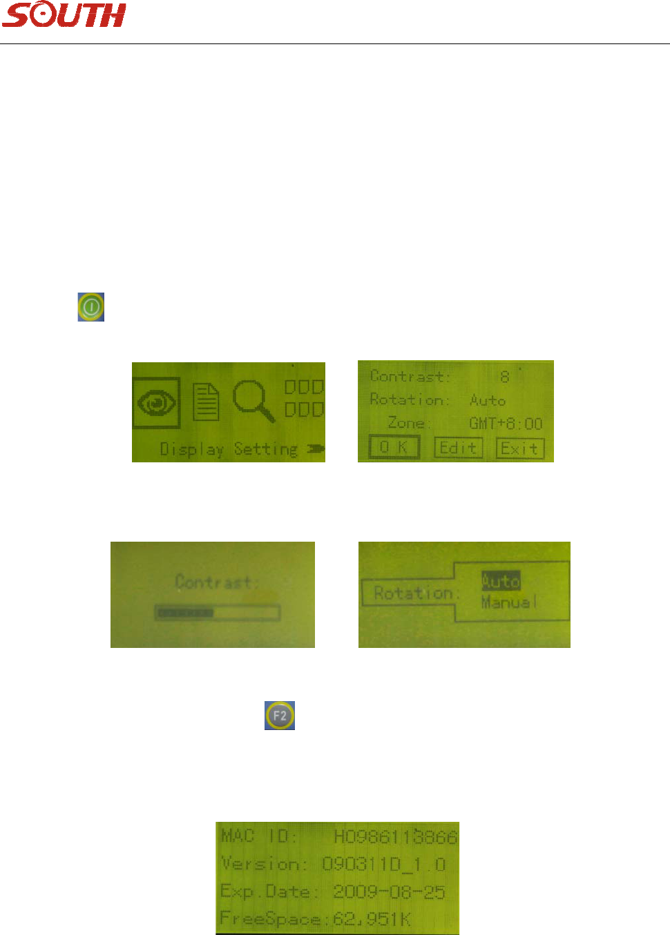
Therovermodeparametersarethesameasthebasemode,justsetitinaccordwithbasemodesettings.
23
4.3.2Systemsetting
Therearefiveoptionsinsystemsettinginterface,displaysetting,systeminfo,self‐check,filelist,
registration,thedetailedoperationsandoptionsareasbelows:
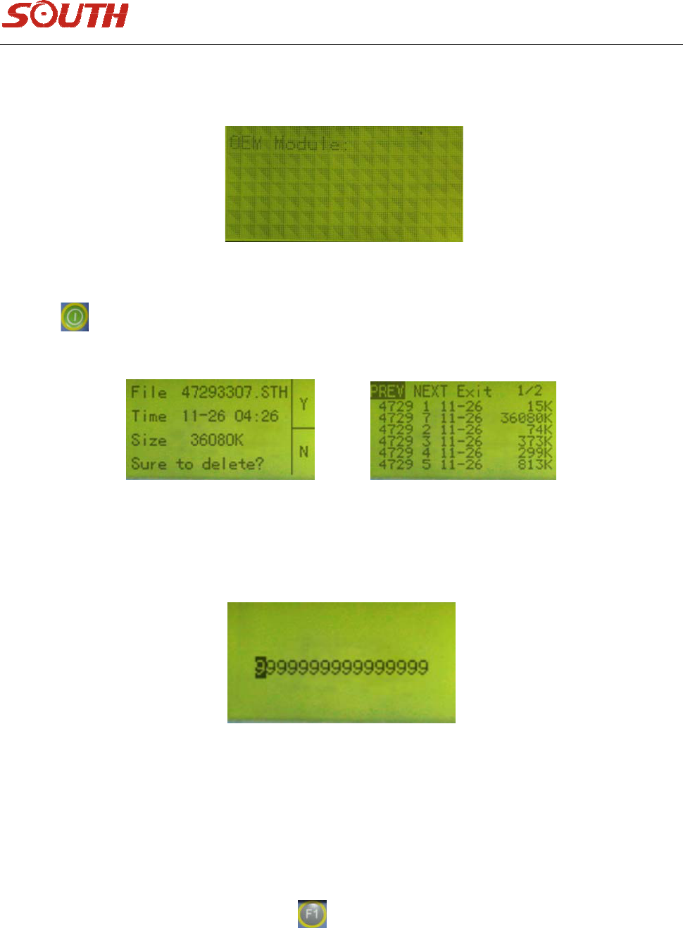
Displaysetting:thereare3optionsinthisinterface,incontrast,rotationandtimezone.
Contrastsetting:forscreencontrastadjustment.
Rotation:forpageturning,automaticormanual.Thereareseveralpagesincollectioninterface,
automaticmeansthesepageswillbedisplayedcircularly,manualmeansyouneedtoturnpagesby
pressingbutton.
Figure4‐16
Figure4‐17
Afterfinishingparameterssetting,pressbuttontopriormenu.
Systeminfo:checkingreceiverserialnumber,firmwareversion,expireddateandfreespaceinmemory.
Seeasfigure4‐18.
24
Figure4‐18
self‐check:checkingscreen,LEDandbeeper,battery.SeeasFigure4‐19
Figure4‐19
Filelist:checkingstaticdatafilesinreceivermemory.checkingfilesize,starttime,endtimeandsoon.
Pressbuttonwhenthecursorisonspecificfile,theconfirm‐deleteframewillpopup,withfile
detailbeingshown.seeasfigure4‐20,
Figure4‐20
Registration:Inthisinterface,youcaninputregistercodemanually,Registrationcodecanbeentered
hereincasenoPCconnectionisavailableinthefield.Onlythelast16Charactersareneeded.seeas
followingfigure,
Figure4‐21
4.4Collectionmode
(1) Staticworkinterface
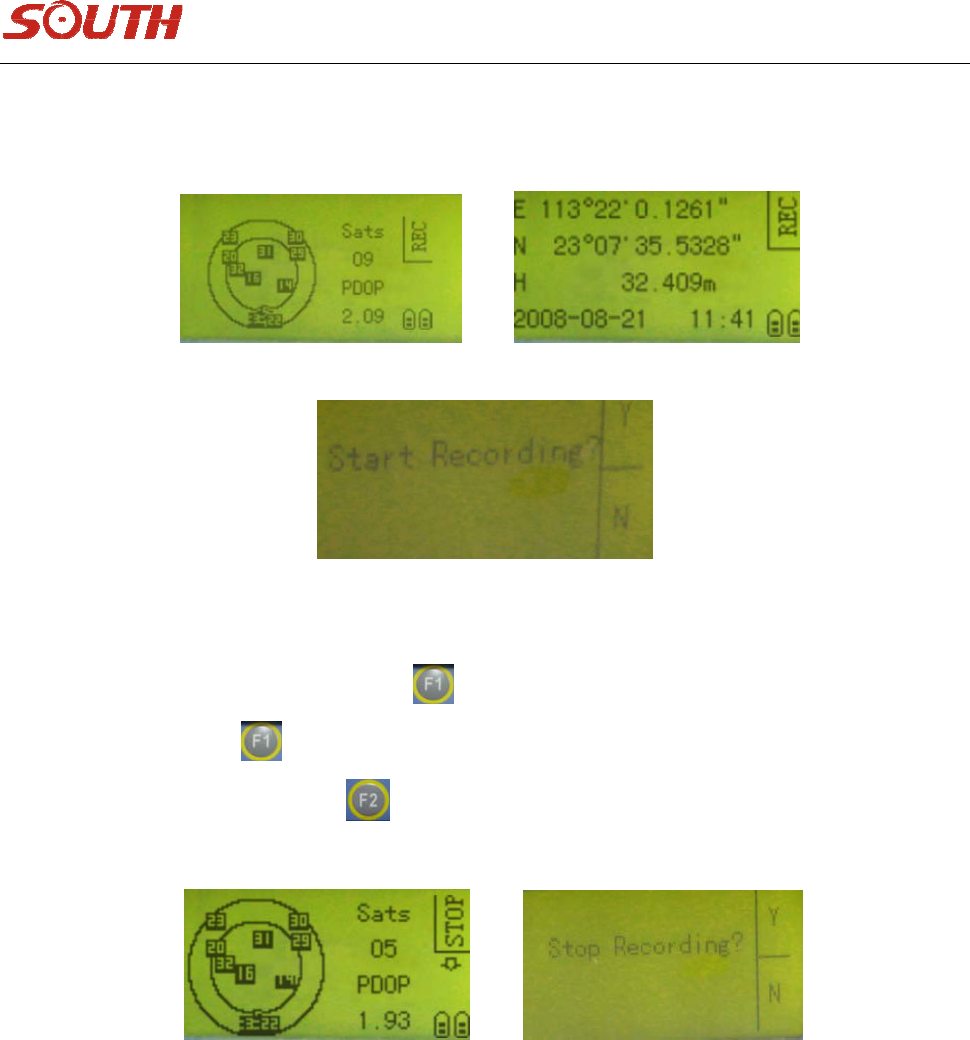
Whenchoosingstaticmodeinsettingmodes,thereceiverwillenterstaticworkmodeafteritbeing
poweredon.Ifmanualwayiswanted,pressbuttontwicetostartrecordingdata.Ifautomaticway
25
chosen,thereceiverwillrecorddataautomatically.Thereare3satelliteinformationinterfacesinthis
mode;youcansetthewayofturningpagesautomaticallyormanually.Seeasfigure4‐22.
Figure4‐22
Ifyouwanttoenddatarecording,pressbutton,thenthesystemwillremindyoutoenddata
recordingornot.pressbuttonagain,systemwillshowyouthatfilesarebeingclosednow.ifyou
wanttocancelthisoperation,pressbutton.Seeasfigure4‐23,
Figure4‐23
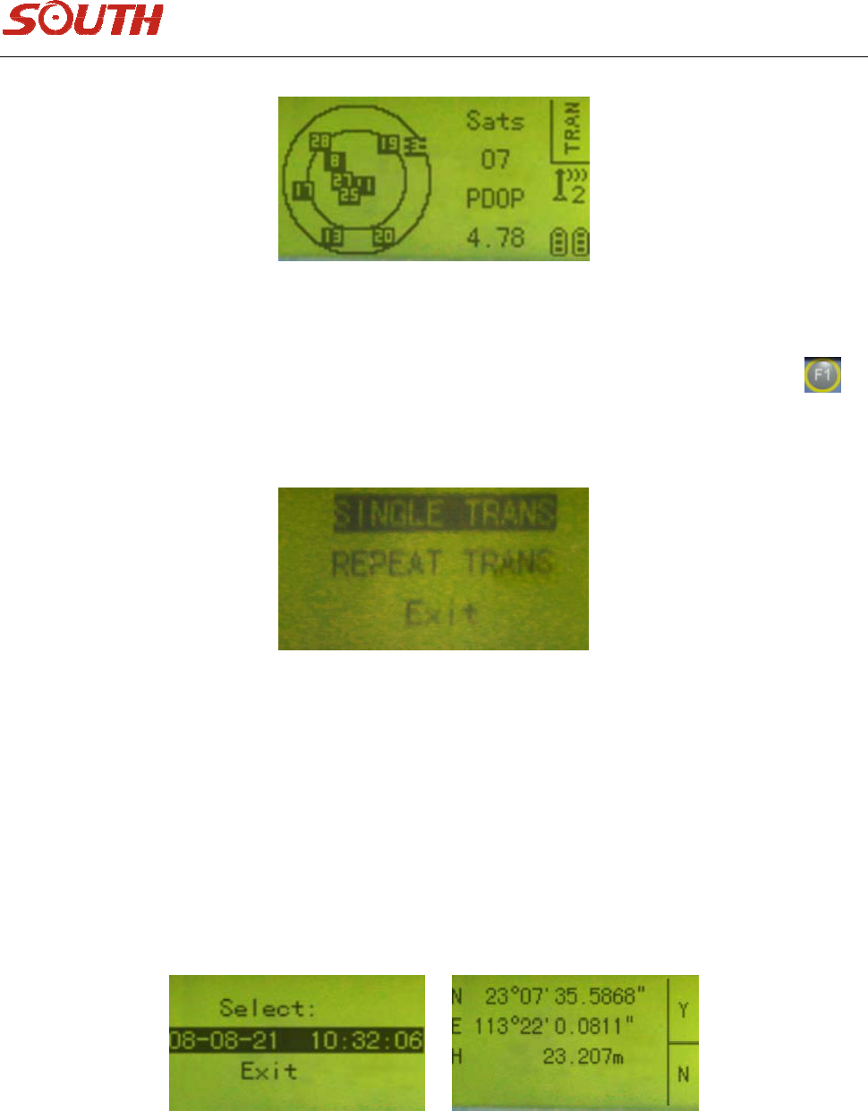
(2) Baseworkinterface
Whenbasemodechoseninsettingmode,receiverwillenterbaseworkmodeafterbeingpoweredon.
Seeasfigure4‐24
26
Figure4‐24
Enteringthisinterface,youwillseetheword“TRANSMIT”ontheup‐rightcornerofscreen,press
buttontoenterbasesetupmenu,seeasfigure4‐25,
Figure4‐25
Thereare3optionsinthismenu,SINGLETRANS
,
REPEATTRANS
,
EXIT
,
instructionsareasbelows,
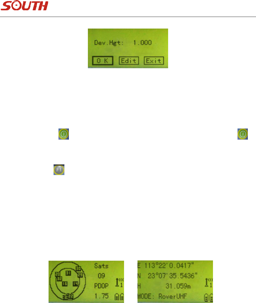
SINGLETRANS:Itmeansusinglocalcoordinateasbasecoordinatetotransmit,youcansavethis
coordinateasabasecoordinatefileafterworkbeingdone.Itcanbeusedfortransmissionrepeating.
REPEATTRANS:Whensettingthebasestationinthesameposition,youcanusetransmissionrepeating
function,inthismenu,coordinatecanbechosentobesavedinreceiver.Seeasthefollowingfigures,
27
Thecoordinatehasbeencalculatedtotheground,sothedeviceheightneedtobeinputbefore
transmission,seeasbelowfigure,it’sdev.Hgt.Youneedtomeasurefrombasepointonthegroundtothe
edgeofHiplate.
EXIT:youcanselectthisitemtoquitoperation.
Afterselecting,press buttontoconfirm,itwillentertheinterfaceasfigure4‐15,pressbutton
againtostart,ifthefixedsatellitesareenough(morethan5)andgoodPDOPvalueavailable(smallerthan
3),itwillshow“Starttransmission!”andTXandDATAlightwillblinksimultaneously.ifyouwanttostop
transmitting,pressbutton,thesystemwillremindifyouwanttosavethebasecoordinateornot,
thecoordinatecanbesavedandusedfortransmittingrepeatingfunction.
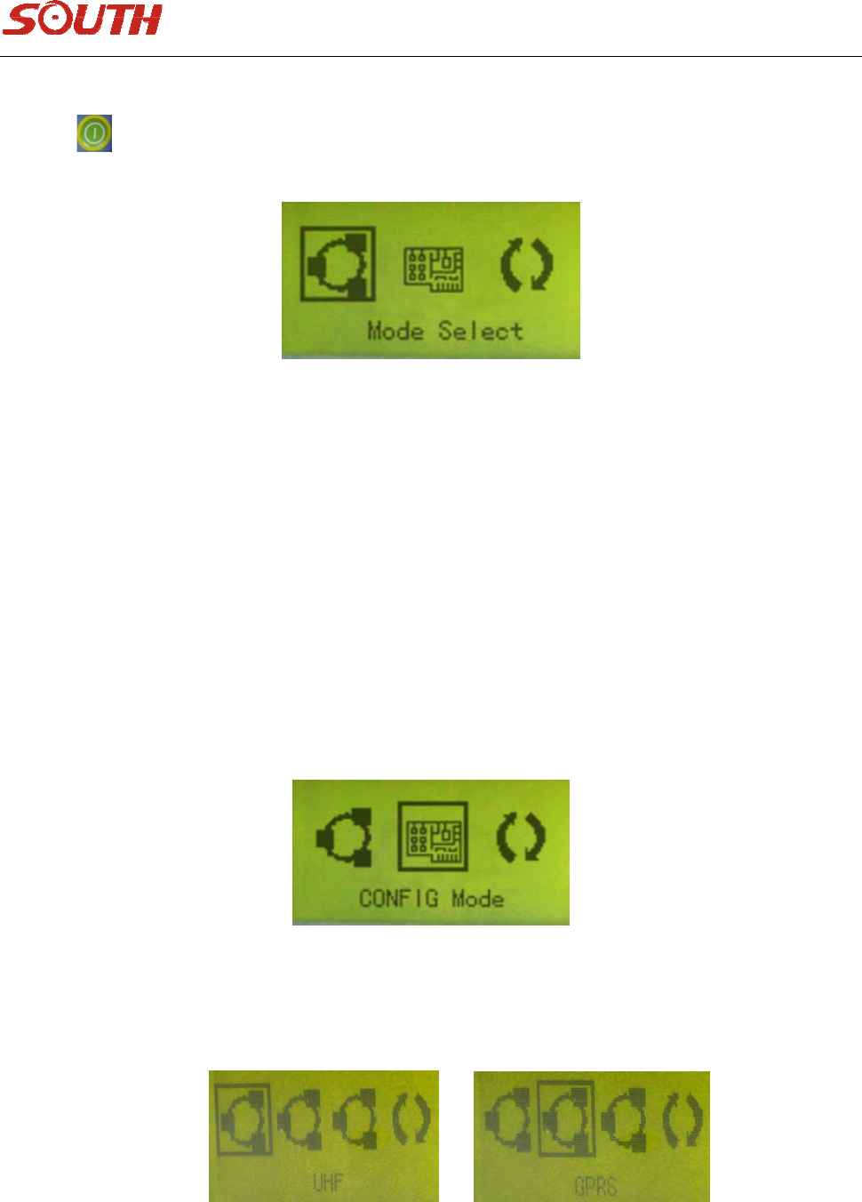
(3)Roverworkinterface
Whenrovermodechoseninsettingmode,thereceiverwillenterroverworkmodeafterbeingpowered
on,seeasfigure4‐26,
Figure4‐26
Therearetwopagesinthecollectionmode.Itincludessatellitesnumber,map,PDOPvalue,radiochannel,
moduleinuse,batterypower,longitude,latitude,ellipsoidheightandsoon.
28
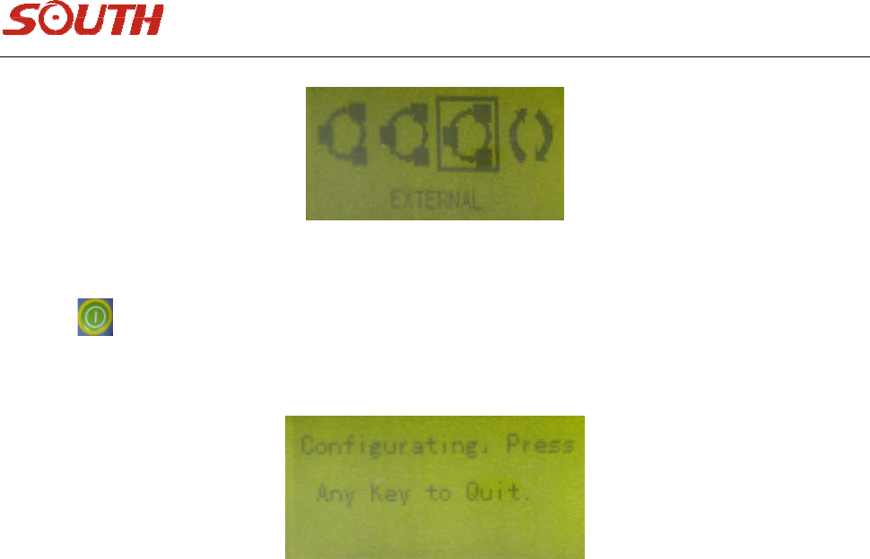
4.5Modulesetting
Pressbuttontoentermodulesettinginterfaceinroverworkmode,seeasfigure4‐27,
Figure4‐27
Note:Inbaseworkmode,youcanonlyentermodulesettinginterfaceafterbasestationtransmitting
signals,andonlymoduleparameterssettingscanbechanged,suchasmodule,channel.workmodecannot
bechangedhere.
Afterroverbeingconnectedtothebase,ifyouwanttochangeradiochannelorchangeradiomodule,
youcanoperateitinmodulesettinginterface,youcanreferto4.3.1aboutdata
linkandchannelsetting.
Figure4‐28
Whenconfigureradio module wanted,enter config modetoset, usually thereceiveris
neededtobeconnectedtoPCprogramstomakethisconfiguration.Seeasfollowingfigure4‐29,
29
Figure4‐29
Pressbuttontoenterconfigurationinterface,youcansetparametersinPCprogramafter
connection,seeasfigure4‐30,
Figure4‐30
Aftersettingsdone,pressanybuttontoreturntocollectioninterface.
30
Chapter5DataManageandTransfer
5.1Howtotransmitdata
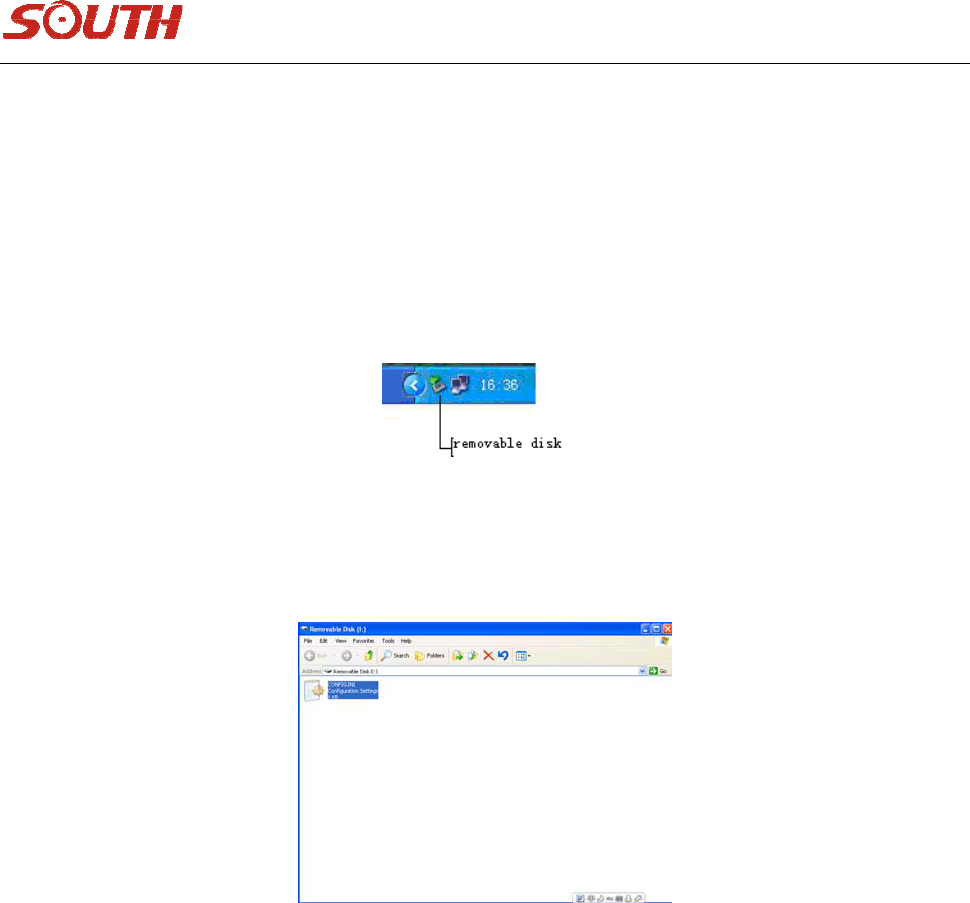
Firstly,connectthereceivertoPCbytheUSBcable,whichworkslikeaflashdiskafterbeingconnectedto
thecomputer.aremovablediskiconwillappearattherightbottomofthecomputerscreen,seeas
figure5‐1.
Figure5‐1
Thenyouwillfinda“removabledisk”in“mycomputer”,clickit,youwillfindthedatainreceivermemory.
Figure5‐2
Therecorddatafileis“*.sth“,theeditingtimeoffileisthetimetofinishdatarecording,thestaticdata
canbecopieddirectlyfromthisdirectory.
Notice:Thenameofdatarecordingiscomposedby8characters,thefirstfourcharactersofwhichispoint
name,themiddlethreecharactersdate,forexample,31th,Janis031.Thelastonesession.
5.2Theuseofconfigurationfile
Whenyouopenthefile“CONFIG”,youwillseeitasbelows:
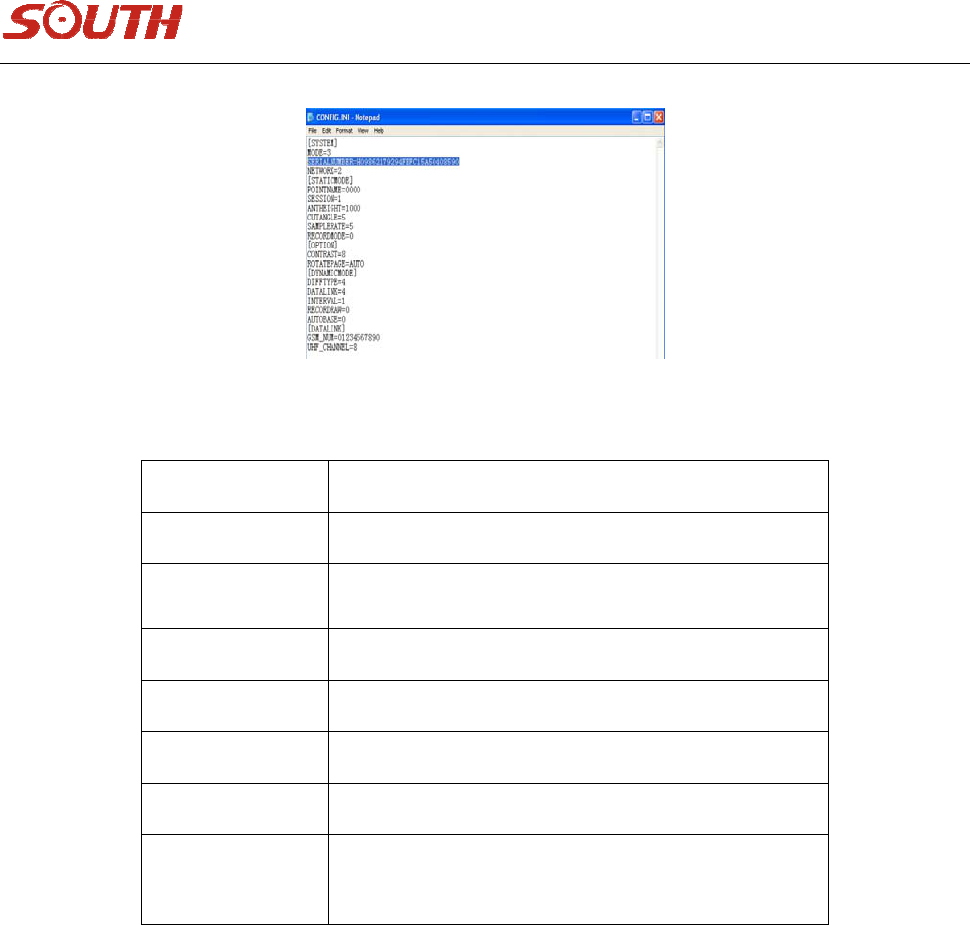
31
Figure5‐3
NameNote
PointNameFourcharacters,from0to9,a,b,c……z
SessionFrom1to9
AntHeightTheUnitismillimeter(mm)
MaskAngleFrom0degreeto45degree
ContrastFrom0to15
LanguageChineseandEnglish
Serial
Number
composedby27digitsanduppercasecharacters.
Ifthefile“CONFIG”isdeleted,itwillregenerateautomaticallyaftertherestartofthereceiver.
5.3Registerandupgrade
5.3.1Register
Thereare4methodstomakeregistration:
1.Modifyconfigurationfile,conf.ini(USBport).Pleaserefertofigure5‐3.Youcanreplacethecontentof
redframe,thensaveit.Theregistrationcodewillbeenteredtothereceiver.
32
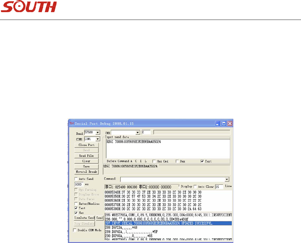
2.Directserialportcommand.ConnectthereceivertoyourPCusingserialport.Useanyserial
communicationsoftware(e.g.SuperTerminal)tosendthefollowingcommandatthebaudrateof
115200bps.
REGIH09862112341111222233334444
NOTE:Yourserialcodeshouldbedifferentfromtheaboveonebutwithsameformation.(COMport)See
asfollowingfigure:
3. Bycontroller.UsecontrollersoftwareEGstar3.0.RefertotheEGstar3.0UserManualfordetailed
information.
4. Inputtheserialportfrompanel.Inthecaseonlythelast16charactersareneeded.SeeRegistrationin
Systemconfigurationsection.Pleasereferto4.3.2aboutregistration.
5.3.2ReceiverUpgrade
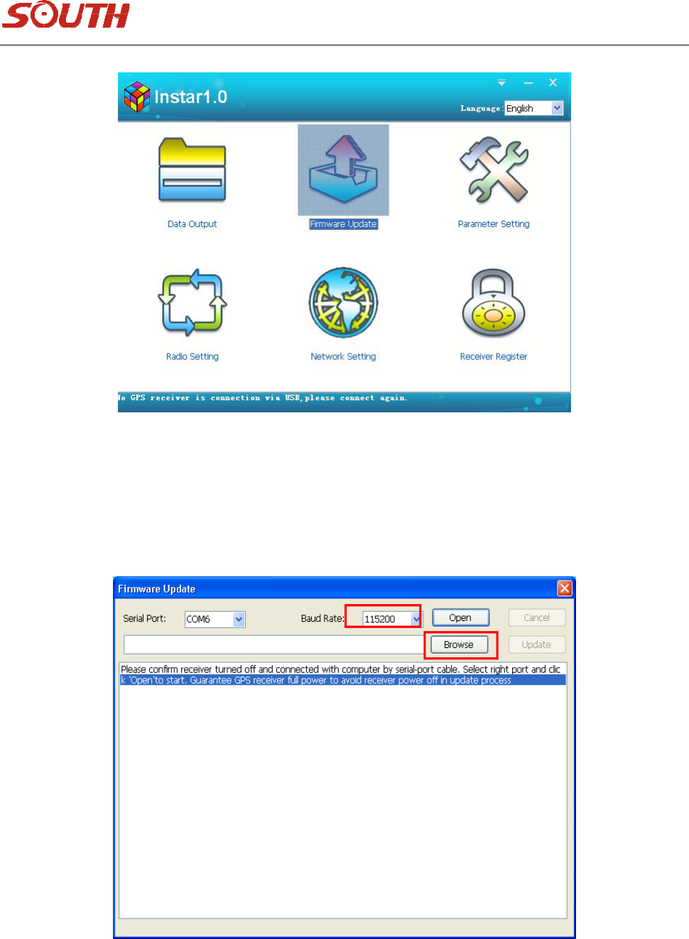
Sometimes,youneedupgradefirmwareofreceiver,withmainprogramInstar.exeandupgradefile*.dat,
theoperationstepsareasbelows.
33
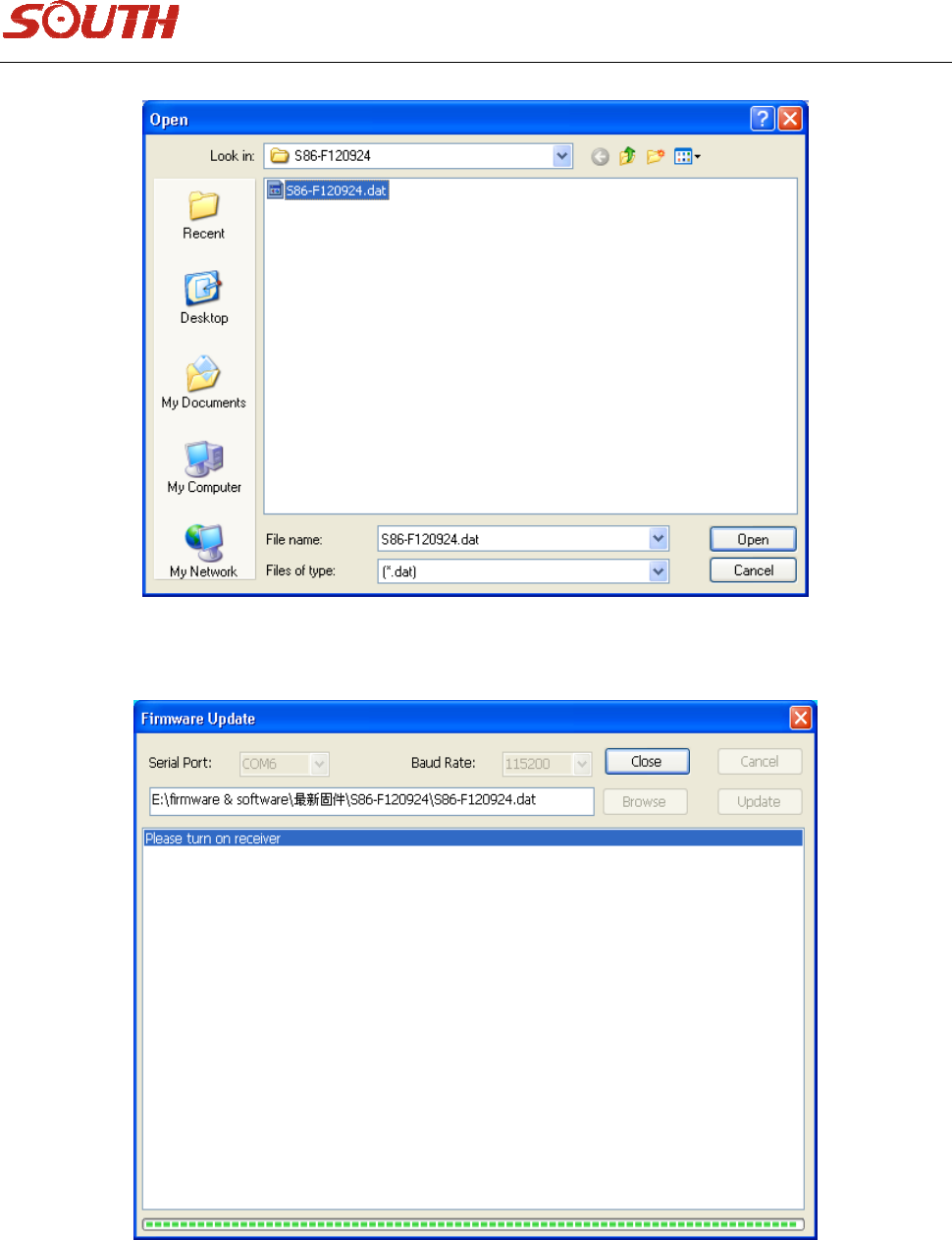
1. KeepS86ToffandconnecttoPCwithaL979Ycable.
2. Doubleclick“FirmwareUpdate”,Instarwillshowasfollows,thenselectthebaudrateto115200and
selectthelatestfirmware.
34
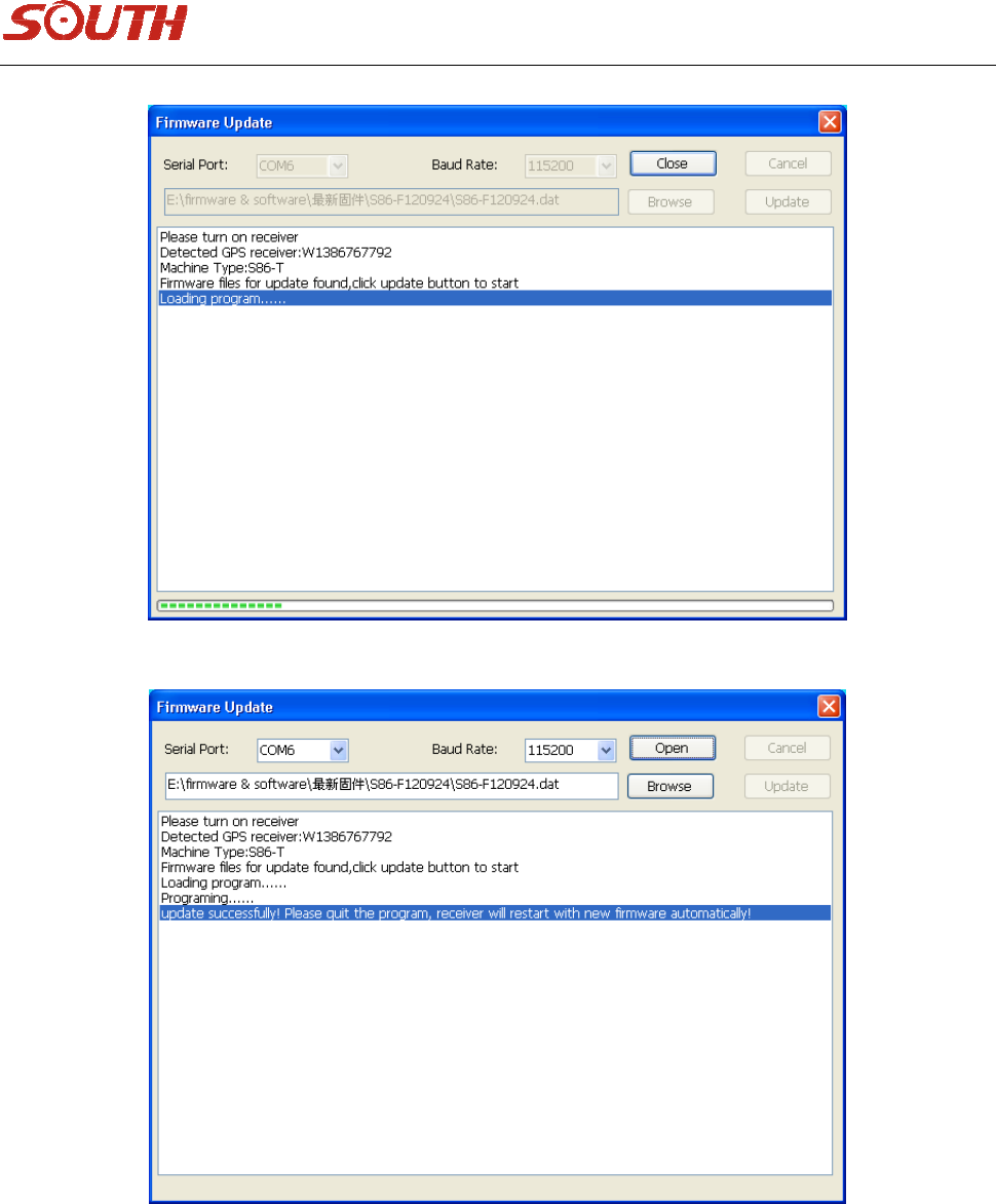
3. TurnonS86Tanditwillmanagetoupdateautomatically.
35

36
Chapter6Statement
6.1FederalCommunicationCommissionInterferenceStatement
ThisdevicecomplieswithPart15oftheFCCRules.Operationissubjecttothefollowingtwoconditions:
1. Thisdevicemaynotcauseharmfulinterference.
2. Thisdevicemustacceptanyinterferencereceived,includinginterferencethatmaycauseundesired
operation.
AndthisequipmenthasbeentestedandfoundtocomplywiththelimitsforaClassBdigitaldevice,
pursuanttoPart15oftheFCCRules.Theselimitsaredesignedtoprovidereasonableprotectionagainst
harmfulinterferenceinaresidentialinstallation.Thisequipmentgenerates,usesandcanradiateradio
frequencyenergyand,ifnotinstalledandusedinaccordancewiththeinstructions,maycauseharmful
interferencetoradiocommunications.However,thereisnoguaranteethatinterferencewillnotoccur
inaparticularinstallation.Ifthisequipmentdoescauseharmfulinterferencetoradioortelevision
reception,whichcanbedeterminedbyturningtheequipmentoffandon,theuserisencouragedtotryto
correcttheinterferencebyoneofthefollowingmeasures:
1. Reorientorrelocatethereceivingantenna.
2. Increasetheseparationbetweentheequipmentandreceiver.
3. Connecttheequipmentintoanoutletonacircuitdifferentfromthat
4. towhichthereceiverisconnected.
5. Consultthedealeroranexperiencedradio/TVtechnicianforhelp.
FCCCaution:
Anychangesormodificationsnotexpresslyapprovedbythepartyresponsibleforcompliancecouldvoid
theuser'sauthoritytooperatethisequipment.
Thistransmittermustnotbeco‐locatedoroperatinginconjunctionwithanyotherantennaor
transmitter.
To comply with FCC's RF radiation exposure limits for general population/uncontrolled exposure, the antenna(s) used
for this transmitter must be installed to provide a separation distance of at least 20 cm from all persons and must not
be collocated or operating in conjunction with any other antenna or transmitter.
