SPAL USA 6RX Remote Control Receiver User Manual rr fcc instructions
SPAL USA Remote Control Receiver rr fcc instructions
SPAL USA >
users manual

FCC ID: KNF6RX
FCC Compliance and Advisory Statement
This device complies with Part 15 of the FCC rules. Operation is subject to the following two
conditions: 1) this device may not cause harmful interference, and 2) this device must accept
any interference received, including interference that may cause undesired operation.
This equipment has been tested and found to comply with the limits for a Class B digital device,
according to Part 15 of the FCC rules. These limits are designed to provide reasonable
protection against harmful interference in a residential installation. This equipment generates,
uses and can radiate radio frequency energy and if not installed and used in accordance with
the instructions, may cause harmful interference to radio communications. However, there is
no guarantee that interference will not occur in a particular installation. If this equipment does
cause harmful interference to radio or television reception, which can be determined by turning
the equipment off and on, the user is encouraged to try correct the interference by one or more
of the following measures:
1.Reorient the receiving antenna.
2.Increase the separation between the equipment and receiver.
3.Connect the equipment into and outlet on a circuit different from that to which the receiver is
connected.
4.Consult the dealer or an experienced radio/TV technician for help.
Any special accessories needed for compliance must be specified in the instruction manual.
Warning: A shielded-type power cord is required in order to meet FCC emission limits and
also to prevent interference to the nearby radio and television reception. It is essential that
only the supplied power cord be used. Use only shielded cables to connect I/O devices to this
equipment.
CAUSION: Any changes or modifications not expressly approved by the party responsible for
compliance could void your authority to operate the equipment.

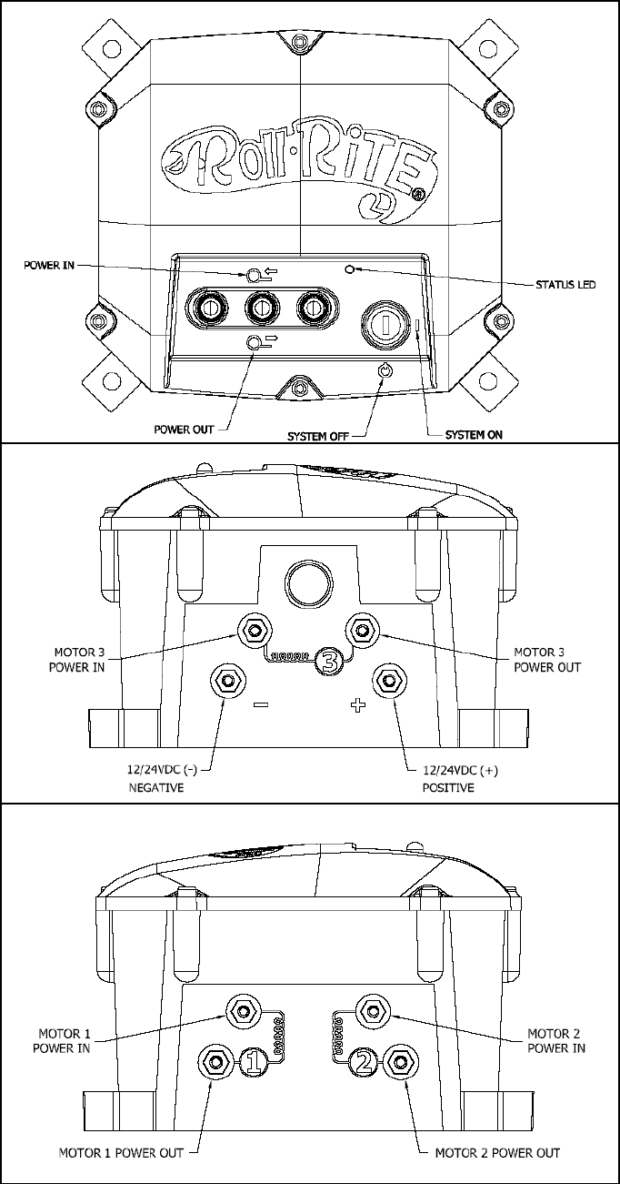
Installation:
1) Mount the enclosure in a secure location. Select a location that will minimize the amount of wire
needed and that is as shielded as possible from the elements.
2) Run a pair of wires (6 awg is recommended) from a 12 Volt battery (do not connect to the
battery at this time) to the box and feed them in through one of the black wire glands.
3) Connect your positive battery wire to the “+” terminal on the case.
4) Connect your negative battery wire to the “-” terminal on the case.
5) Run a pair of wires (6 awg is recommended) from the first motor you wish to control to the box
and connect them to the motor 1 outputs.
6) Repeat steps 5 for the optional second and third motors.
7) Connect the motor wires to the motors using the terminals provided.
8) Connect the battery wires to the battery, splicing the included circuit breaker into the positive wire
as close to the battery as possible. Use the terminals provided.
9) Using one of the included keys, un-lock the keyed switch to allow the controls to operate.
10) Verify that the motors operate in the correct direction when the manual toggle switches are used.
Swapping the two wires hooked to the back of each motor will reverse its rotation.
11) Verify that the first motor operates correctly when the “I” and “II” key fob buttons are pressed and
held and that the second motor operates correctly when the “III” and “IV” key fob buttons are
pressed and held. If the motors operate at the incorrect time check that the wires are connected to
the proper output.
Operation:
The outputs may be controller via the front mounted toggle switches or the 6 button remote keyfob. The
power in direction of the toggle switch corresponds to the odd numbered buttons on the keyfob. And the
opposite toggle direction, power out, is consistent with the even numbered keyfob buttons.
IMPORTANT Always have the function you are activating in sight during use to facilitate diagnosis of
any possible mechanical or electrical problems.
Input voltage selection, if your unit has been equipped with 24 volt contactors the dip switches on the 2
switch bank should both be in the ON position. If using on 12-volt equipment leave both these switches in
the OFF position.

Programming/Re-Programming Transmitter:
Before you begin, here are some hints:
• The included keyfobs are pre-programmed from the factory to match the included receiver.
• Before beginning, gather all of the keyfobs that you wish to program. The receiver will store codes
for up to four keyfobs, but all must be programmed at the same time. Programming an additional
keyfob at a later date will erase all previously stored keyfob codes.
• The receiver automatically exits programming mode if it detects no activity for 10 seconds. If this
happens before you finish, you will need to start over at Step 1. Reading all the way through the
instructions before beginning will help.
Programming Instructions:
1) Turn the keyed switch on and wait for the solid green LED
2) Turn the key switch off/on rapidly 5 times. If the led goes out during the process, you are switching too
slowly. Leave the key in the on position after the 5
th
cycle. With the key in the on position the LED
should now show solid red.
3) Press any button on the first keyfob until the LED on the receiver blinks. Repeat for any remaining
keyfobs.
4) When finished, simply wait 10 seconds for the receiver to exit programming mode (the light will go back
to solid green).
If you have any questions, please call our Customer Service Department at 1-800-297-9905.
Roll Rite
2574 School Road
Alger, MI 48610