SPOK Aus INTELPAGE Paging Transmitter User Manual Manual
SPOK Aus Pty. Ltd. Paging Transmitter Manual
SPOK Aus >
Manual

Installation & Configuration Guide for
Intelpage IP
Amcom Software, Inc.
Copyright
Intelpage IP v2.12 Firmware
Document Version 1.0
Last Saved Date: October 10, 2013
Copyright 2003-2013 Amcom Software, Inc. All Rights Reserved.
Information in this document is subject to change without notice. The software described in this document is
furnished under one or more Program/Product License Agreements. The software may be used or copied only in
accordance with the terms of those agreements. No part of this publication may be reproduced, stored in a retrieval
system, or transmitted by any means electronic or mechanical, including photocopying and recording for any
purpose without the written permission of Amcom Software, Inc.
Amcom Software, Inc.
10400 Yellow Circle Drive
Suite 100
Eden Prairie, MN 55343
USA
Trademarks
Microsoft and Windows are trademarks of Microsoft Corporation. Other brands and their products are trademarks or
registered trademarks of their respective holders and should be noted as such.

Installation & Configuration Guide for Intelpage IP Contents
iii
Contents
Intelpage IP 1
Intelpage IP ......................................................................................................................... 1
Compliance Information ..................................................................................................... 1
Safety and General Information .......................................................................................... 3
About the Intelpage IP 4
About the Intelpage IP ........................................................................................................ 4
Intelpage IP Kit .................................................................................................... 4
LEDs and Connectors ......................................................................................................... 5
LED Indicators ..................................................................................................... 6
Connectors ............................................................................................................ 6
LCD Display (High Power Version Only) ........................................................... 7
Installation 8
Installation .......................................................................................................................... 8
Rack Version ...................................................................................................................... 8
Desktop Version ................................................................................................................. 9
Configuration 10
Configuration .................................................................................................................... 10
Connecting ........................................................................................................................ 10
Logging In ........................................................................................................................ 13
User Interface Fields ......................................................................................................... 14
Home .................................................................................................................. 14
Pagers ................................................................................................................. 15
Network Settings ................................................................................................ 16
Serial Port Settings ............................................................................................. 17
Transmitter Settings............................................................................................ 18
Protocol .............................................................................................................. 19
Pocsag ................................................................................................................. 21
Password ............................................................................................................. 22
IP Access List ..................................................................................................... 23
Site Survey ......................................................................................................... 24
Status .................................................................................................................. 25
Licensing ............................................................................................................ 26
Configuration Examples 28
Configuration Examples ................................................................................................... 28
Setting up Dial-in TAP to Intelpage IP from Messenger .................................................. 28

Intelpage IP
2 Installation & Configuration Guide for Intelpage IP
Appendix 30
Appendix .......................................................................................................................... 30
Configuring Network Settings Through the Terminal Interface ....................................... 30
Transmitters ...................................................................................................................... 34
Installing Multiple Transmitters and Aerials ...................................................... 34
VSWR ................................................................................................................ 34
Types of Antennas ............................................................................................................ 35
Technical Specifications ................................................................................................... 36
General ............................................................................................................... 36
Desktop Version Specific ................................................................................... 36
5 Watt Rack Version Specific ............................................................................ 36
High Power Version Specific ............................................................................. 37

Installation & Configuration Guide for Intelpage IP Intelpage IP
1
Intelpage IP
Intelpage IP
Installation
“Installation” on page 8 includes information on how to install the Intelpage IP system.
Configuration
“Configuration” on page 10 includes information on how to connect and log into the Intelpage IP system. In
addition, information on the user interface fields on the following topics are included: home, send a message, pagers,
network settings, serial port settings, transmitter settings, protocol, POCSAG, password IP access list, survey, status,
and licensing.
Configuration Examples
“Configuration Examples” on page 28 includes an example configuration for the Intelpage IP system. The
information covers how to set up a dial-in TAP to the Intelpage IP from Messenger.
Appendix
“Appendix” on page 30 includes information on cable pin-outs, technical information, and technical specifications
for the Intelpage IP product.
Compliance Information
SAA (AUSTRALIA)
To ensure compliance with ACA Technical Standards, this equipment is labeled with a Telecommunications
Compliance label. For safety reasons, this equipment should only be connected to compliant telecommunications
equipment in accordance with the manufacturer’s instructions.
FCC (USA)
Part 15
This equipment has been tested and was found to comply with FCC Rules and Regulations, Part 15 with the limits of
a Class B digital device, designed to provide reasonable protection against harmful interference. This equipment
generates, uses, and can radiate frequency energy and if not installed and used in accordance with the instructions,
may cause interference harmful to radio communications. On the base of the equipment is a label containing an FCC
Registration Number, if applicable.

Intelpage IP
2 Installation & Configuration Guide for Intelpage IP
Part 90
This equipment has been tested and found to comply with FCC Rules and Regulations, Part 90.
FCCID: T5GPT5
IC (INDUSTRY CANADA, INDUSTRIE CANADA)
This class B digital apparatus complies with Canadian ICES-003. IC: 4767A-PT5
CE (EUROPE)
Amcom Software declares under our sole responsibility that the product Intelpage IP to which this declaration
relates, is in conformity with the following standards and/or other normative documents.
- EN 300 224-2 v1.1.1 (2001-01)
- EN 55022: 1994 +A1: 1995 +A2: 1997
- EN 301 489 -2 v1.3.1 (2002-08)
- EN 60950-1: 2001
We hereby declare that all essential radio test suites have been carried out and that the above named product is in
compliance to all the essential requirements of Directive 1999/5/EC.
The conformity assessment procedure referred to in Article 10(5) and detailed in Annex IV of Directive 1999/5/EC
has been followed with the involvement of the following notified body:
Bay Area Compliance Laboratory Corporation, 1274 Anvilwood Ave., Sunnyvale, CA 94089, USA
Identification mark: 1313 (Notified Body Number)
The equipment also carries the class 2 equipment identifier (exclamation mark).
The technical documentation relevant to the above equipment can be made available for inspection on application to
Amcom Software.
ROHS & WEEE
To minimize the environmental impact and take more responsibility for the world in which we live, Amcom
Software hereby confirms that the following product series comply with Directive 2002/95/EC (RoHS) and
2002/96/EC (WEEE) of the European Parliament.

Installation & Configuration Guide for Intelpage IP Intelpage IP
3
Safety and General Information
This section includes important information on safe and efficient operation. Please read the following information
before using the unit
Exposure to Radio Frequency Energy
Your Intelpage IP contains a low power radio transmitter. When it is ON, it transmits radio frequency (RF) energy.
Your Intelpage IP is designed to comply with the following national and international standards and guidelines
regarding exposure of human beings to radio frequency electromagnetic energy (EME):
United States Federal Communications Commission, Code of Regulations; 47 CFR part 2 sub-part J
American National Standards Institute (ANSI) / Institute of Electrical and Electronic Engineers (IEEE)
C95. 1-1992
Institute of Electrical and Electronic Engineers (IEEE) C95.1-1999 Edition
National Council on Radiation Protection and Measurements (NCRP) of the United States, Report 86, 1986
International Commission on Non-Ionizing Radiation Protection (ICNIRP) 1998
National Radiological Protection Board of the United Kingdom 1995
Ministry of Health (Canada) Safety Code 6. Limits of Human Exposure to Radiofrequency Electromagnetic
Fields in the Frequency Range from 3 kHz to 300 GHz, 1999
Australian Communications Authority Radio communications (Electromagnetic Radiation-Human
Exposure) Standard 1999
To assure optimal performance and make sure human exposure to radio frequency electromagnetic energy is within
the guidelines set forth in the above standards, always adhere to the procedures outlined below.
Antenna Care
Use only the supplied or an approved replacement antenna. Unauthorized antennas, modifications, or attachments
could damage the device. Do NOT hold the antenna when the device is in use. Holding the antenna affects signal
quality and may cause the Intelpage IP to operate at a higher power level than needed. Do not use Intelpage IP with a
damaged antenna. If a damaged antenna comes into contact with your skin, a minor burn can result. The Intelpage IP
antenna port should only be connected to internal antennas located in the same building as the main equipment.
Electromagnetic Interference/Compatibility
Nearly every electronic device is susceptible to electromagnetic interference (EMI) if inadequately shielded,
designed, or otherwise configured for electromagnetic compatibility.
SELV warning
The Fusion Intelpage IP and Alarm Dispatch modules have been assessed as SELV throughout, all ports shall be
connected to approved SELV circuits or an approved isolation unit shall be used.
Potentially Explosive Atmospheres
Do not operate the Intelpage IP in any area with a potentially explosive atmosphere. Sparks in a potentially explosive
atmosphere can cause an explosion or fire resulting in bodily injury or even death. Areas with potentially explosive
atmospheres include fueling areas such as below decks on boats, fuel or chemical transfer or storage facilities, areas
where the air contains chemicals or particles such as grain, dust, or metal powders, and any other area where you
would normally be advised to turn off your vehicle engine. Areas with potentially explosive atmospheres are often
but not always posted.
Blasting Caps and Areas
To avoid possible interference with blasting operations, do not use the Intelpage IP near electrical blasting caps, in a
blasting area, or in areas posted: “Turn off two-way radio.” Obey all signs and instructions.
About the Intelpage IP
4 Installation & Configuration Guide for Intelpage IP
About the Intelpage IP
About the Intelpage IP
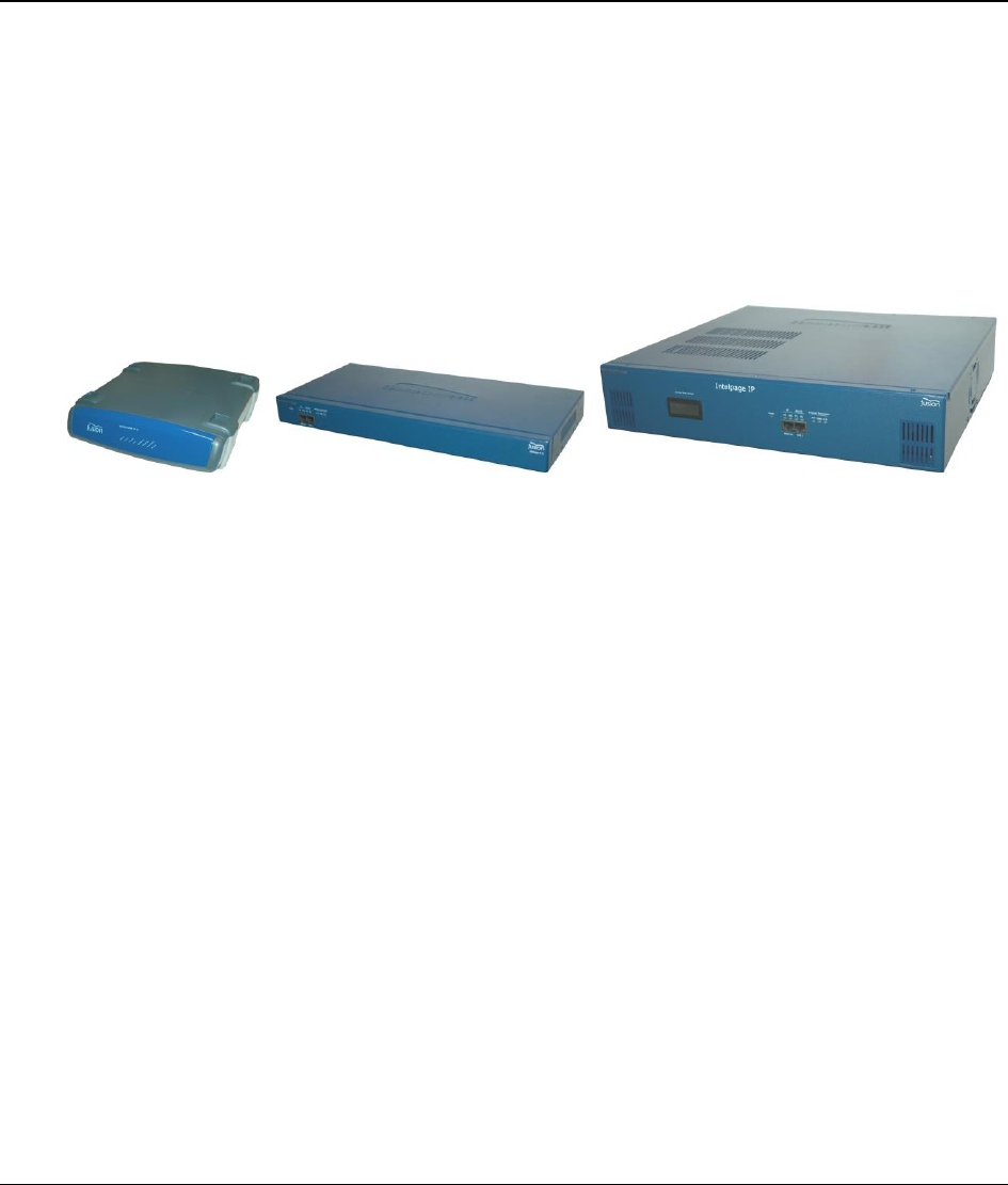
The Fusion Intelpage IP is a high quality paging transmitter capable of encoding serial or TCP/IP data into
POCSAG.
Intelpage IP supports numerous industry standard protocols such as TAP (PET or IXO), COMP, SCOPE, TNPP, and
Waveware (Tekk).
Intelpage IP includes both an RJ45 Ethernet port and an RJ45 RS232 port. This enables system programming and
Ethernet or serial input from third-party systems. In addition, both ports can be used simultaneously and may be set
to different protocols, thus allowing greater flexibility.
Intelpage IP Kit
Your Intelpage IP kit contains:
Intelpage IP unit
Communications cables
Green – Crossover serial cable (RJ45 to RJ45)
Black – Serial cable (RJ45 to DB9 female)
Blue – Straight through Ethernet cable (RJ45 to RJ45)
Red – Crossover Ethernet cable (RJ45 to RJ45)
An Intelpage IP Quick Setup Guide
CD containing manuals and configuration programs
Plus if you ordered a desktop version Intelpage IP:
12 VDC power supply with mains cable
Plastic wall mount bracket
Whip antenna with right angle adapter
Installation & Configuration Guide for Intelpage IP About the Intelpage IP
5
Or if you ordered a 5 watt 19” Rack version Intelpage IP:
IEC Mains power cable
Pack including 2 x rack ears, 6 x black countersunk screws, 4 x rubber feet
N-type to BNC right angle adapter
Whip antenna
Or if you ordered a high power 19” Rack version Intelpage IP:
IEC Mains power cable
Pack including 2 x rack ears, 6 x black countersunk screws, 4 x rubber feet
NOTE: As part of the installation of your Intelpage IP 25/50/100 unit, an antenna capable of handling the power
from the rack amp is also required. The type of antenna used must be carefully chosen depending on the site and
power output of the transmitter.
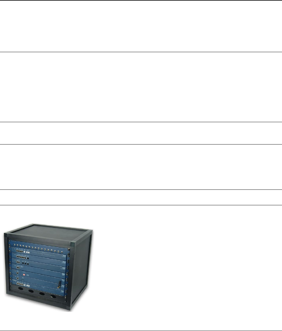
LEDs and Connectors
Depending on which type of Intelpage IP you have purchased, the connector and LED layout are slightly different.
The rack versions have all of their connectors and LEDs on the front panel as shown below.
The only exception is the mains input IEC connector and the antenna connector. You are supplied with a mains lead
in the Intelpage IP kit which plugs straight into this IEC connector.
The antenna port is an opening to allow connection of the antenna to the internal transmitter. The connector is a
standard N-type 50ohm.

About the Intelpage IP
6 Installation & Configuration Guide for Intelpage IP
The desktop version has all of its LED indicators on the front panel while all of the connectors are on the rear panel.
The desktop version is supplied power via the “Power 12VDC” connector. The Intelpage IP requires 12VDC @
2amps regulated. You are supplied with a suitable power supply with mains lead which plugs straight into this
socket.
The antenna port is an opening to allow connection of the antenna to the internal transmitter. The connector is a
standard BNC 50ohm.
LED Indicators
Power Indicator
Power (Yellow) - Indicates that power is applied to the back of the unit and that it is operational.
Transmitter Indicators
Tx PTT (Yellow) - Indicates that the externally connected POCSAG transmitter is currently busy
transmitting (“Keyed up”).
Tx Data (Red) - Indicates POCSAG data activity.
C.D. (Yellow) – Indicates that the unit is initializing (may remain on for 30 seconds at startup if DHCP
is used) or indicates channel is busy (Carrier Detect).
Serial Indicators
RS232 Tx (Red) - Indicates that the receive line of the serial port is active.
RS232 Rx (Green) – Indicates that the transmit line of the serial port is active.
Ethernet Indicators
IP Activity (Green) - Indicated activity on the network.
IP Link (Green) - Indicates device is successfully connected to the network.
Connectors
Ethernet
The RJ45 Ethernet port may be used for connection to a PC, LAN, or external system for configuration and
operational purposes.
The RJ45 port on Intelpage IP is an Ethernet port like any other that may be found on a PC or network device. The
Intelpage IP supports 10Mbps Ethernet connections.
If the Intelpage IP is to be connected to a PC network (i.e. into a switch or hub), then a straight-through cable should
be used. A straight through Ethernet cable is included in the package (blue cable).
If the Intelpage IP is to be connected directly to a single PC or directly to another Ethernet enabled Fusion Series
product, an RJ45 crossover cable should be used. An Ethernet crossover cable is included in the package (red cable).
NOTE: Ensure that the switch/PC you are connecting the Intelpage IP to is set to auto-negotiate the link speed,
otherwise set it to 10Mbps half-duplex.

Installation & Configuration Guide for Intelpage IP About the Intelpage IP
7
RS232
The RS232 port may be used for connection to a PC or external system for configuration or operational purposes.
The pinouts are described below.
Pin No.
Name
Dir
Description
1
2
3
4
GND
System Ground
5
RXD
IN
Receive Data
6
TXD
OUT
Transmit Data
7
CTS
IN
Clear to Send
8
RTS
OUT
Request to Send
LCD Display (High Power Version Only)
The front panel contains a digital panel meter that displays the amount of current the power amp is drawing;
therefore, it is a useful diagnostic tool.
The table below shows the nominal values that will be displayed when viewing each reading while the unit is
transmitting.
Model Number
Amps
25 watt transmitter
5.0 – 8.0
50 watt transmitter
11.0 – 12.0
100 watt transmitter
17.0 – 19.5
Installation
8 Installation & Configuration Guide for Intelpage IP
Installation
Installation
Follow the relevant section below. Depending on which type of Intelpage IP you have purchased, the installation is
slightly different.
Rack Version
Before mounting the enclosure, you need to decide where to place the unit. The Intelpage IP can be desk mounted or
installed into a standard 19 inch rack frame.
Your Intelpage IP package contains four rubber feet which can be placed on the underside of the unit if you wish to
desk mount it.
If the unit is to be rack mounted, you need to attach a pair of rack ears. Your Intelpage IP package contains a set of
rack ears and six screws. Use a Phillips screwdriver to attach the ears to the unit.
WARNING: With the high power 25/50/200 watt versions, do not cover any of the front, rear, or top vents on the
unit with objects or other equipment. If the transmitter is being rack mounted, ensure there is a gap of at least 2 rack-
units (10cm / 4 inches) above the top panel. This ensures the transmitter has adequate ventilation.
A suitable antenna capable of handling the rated power continuously must be connected to the N-type connector on
the rear panel. The antenna for the unit must not be mounted within 10 meters of any other sensitive electronic
equipment including other Fusion series products, routers, computers, or phone systems. The antenna should have its
VSWR checked before connecting the transmitter to it. See the “Transmitters” section on page 34 for more
information regarding antenna choice and VSWR.
WARNING: With the high power 25/50/200 watt versions, The antenna should be mounted so as to maintain a distance
of at least 89CM between the antenna and bystanders, when operated in a typical installation and a 4 dBi antenna.
Use the supplied IEC mains power lead to connect 110-240VAC 50/60 Hz supply to the Intelpage IP unit.

Installation & Configuration Guide for Intelpage IP Installation
9
Desktop Version
Before mounting the enclosure, you need to decide where to place the unit. The Intelpage IP comes with rubber feet
installed, allowing it to sit on a desk or table, or be stacked upon other plastic Fusion Series modules.
The kit also includes a wall mounting bracket. To install this bracket:
1. Use a Philips screwdriver to remove the four screws holding the rubber feet.
2. Seat the bracket on the base of the unit. It only fits one way around.
3. Use the screws that used to hold the rubber feet in position to hold the wall mount bracket in position.
Configuration
10 Installation & Configuration Guide for Intelpage IP
Configuration
Configuration
Information on how to configure the Intelpage IP system is included in this section.
Connecting
“Connecting” on page 10 includes information on how to connect to the Intelpage IP system.
Logging In
“Logging In” on page 13 includes information on how to log into the Intelpage IP system.
User Interface Fields
“User Interface Fields” on page 14 includes information on the fields included in the user interface. The portions that
are covered include: home, send a message, pagers, network settings, serial port settings, transmitter settings,
protocol, POCSAG, password, IP access list, survey, status, and licensing.
Connecting
In order to view the user interface, you must first connect to the Intelpage IP via its Ethernet port. There are two
ways that you can connect to the unit.
1. Directly with a PC or laptop using the supplied crossover Ethernet cable (red RJ45 - RJ45).
2. Connect the unit to a local area network (LAN) by connecting it to a spare port or to a switch/hub using the
supplied straight through Ethernet cable (blue RJ45 - RJ45).
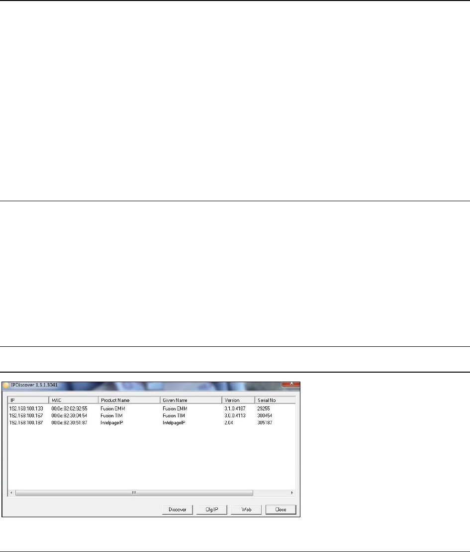
Once you have plugged in the unit you can use a utility called IPDiscover to locate your Intelpage IP on the network
and start a web session with the unit. This program is included within the “IPDiscover” folder on the CD included in
the package. Run the program and you see all Fusion Series products on the network.
NOTE: DHCP is enabled by default. If no DHCP server is found on the network, the default IP of 192.168.0.100 is
used.
Installation & Configuration Guide for Intelpage IP Configuration
11
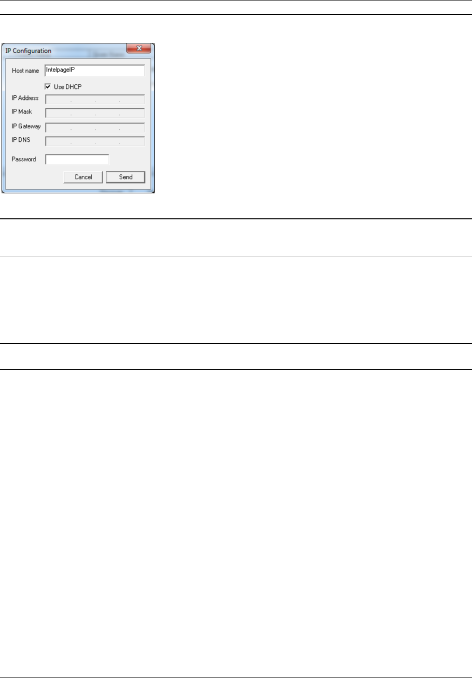
In the example above, there is an Intelpage IP on the network at IP Address 192.168.100.187. If you would like to
configure the IP settings of this unit you may click the CfgIP button. You can then turn off DHCP if it is not
required or change the unit’s IP Address.
NOTE: By default, there is no password required to configure these settings in IPDiscover.
NOTE: If you cannot connect to the Intelpage IP, you should set your PC’s network card IP address to be on the
same subnet as the Intelpage IP. For example, if the Intelpage IP is set to 192.168.1.100, you should set your PC IP
address to 192.168.1.x (where x is 1-254).
If you are happy with the IP settings, perform the following actions:
a. Highlight the unit in the IPDiscover program.
b. Click the Web button. A browser window opens, displaying the login screen, as shown below. The
Fusion Intelpage IP user interface is provided via a web page, meaning that it can be accessed remotely
from any PC on the network. For the best results, Internet Explorer 6 or higher should be used.
NOTE: IE8/IE9 can also be used; however, “Compatibility Mode” may need to be enabled to correctly display the
webpages.
Configuration
12 Installation & Configuration Guide for Intelpage IP
NOTE: If you are having issues accessing the Intelpage web interface, some basic networking settings such as the
Hostname, IP Address, and DHCP settings can also be configured using the built in Terminal interface. See later on
in this manual for details on this.

Installation & Configuration Guide for Intelpage IP Configuration
13
Logging In
Click on one of the menu items on the left-hand side to bring up the authorization window as shown below.
1. In the User name field, enter maint.
2. In the Password field, do not enter information.
3. Click the OK button. You are logged in.
Configuration
14 Installation & Configuration Guide for Intelpage IP
User Interface Fields
The section below explains the various menus and fields on the web interface.
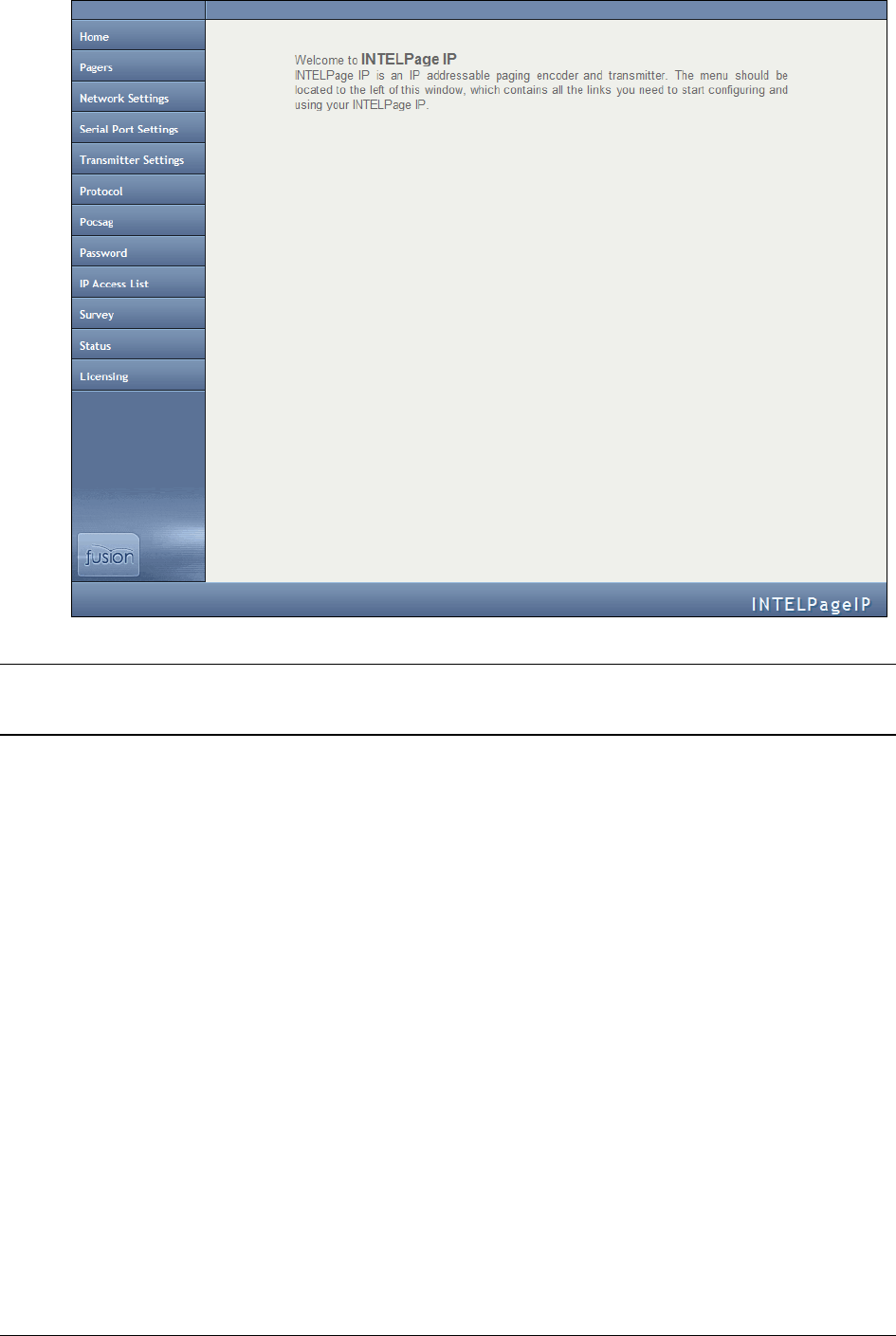
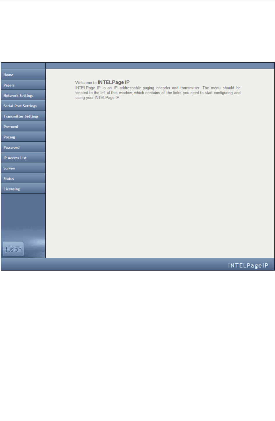
Home
Clicking this menu returns you to the main page.
Installation & Configuration Guide for Intelpage IP Configuration
15
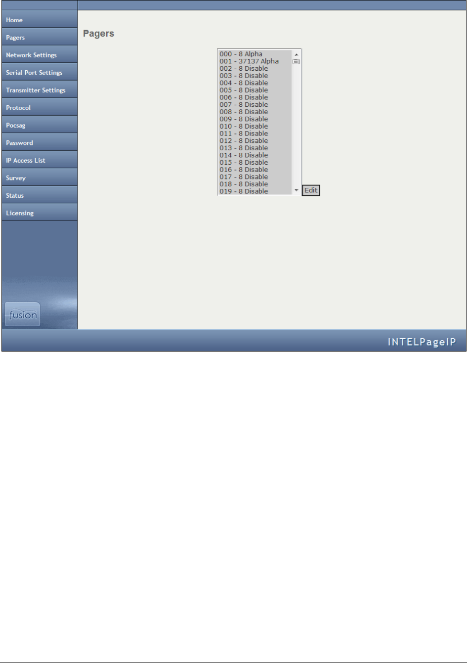
Pagers
This screen is used to edit Intelpage IP’s internal pager database.
The Intelpage IP supports pager IDs from 000 to 999. To enable or edit a pager ID, choose an item from the list and
click the Edit button.
Enter in the required cap code and set the encoding type to one of the following:
Tone Only
Numeric
Alphanumeric
Disabled (Disables the Pager ID)
Configuration
16 Installation & Configuration Guide for Intelpage IP
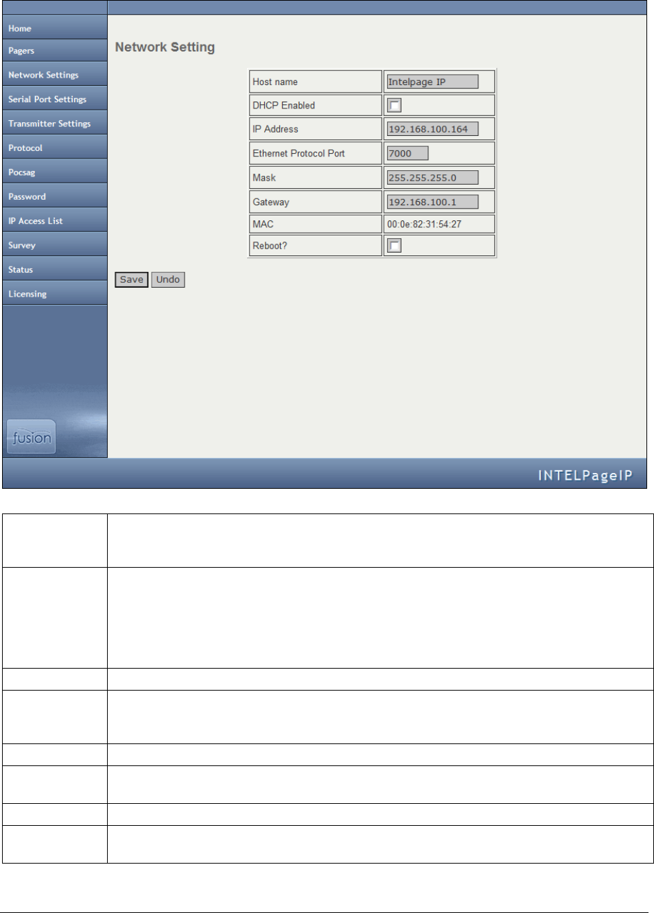
Network Settings
This screen is used to edit Intelpage IP’s networking settings.
Hostname
Here you can give your Intelpage IP a name on the network. This name shows up in the
IPDiscover utility. Giving a unique name allows multiple IP based Fusion series devices to be
easily located and managed.
DHCP
Enabled
By default, this option is enabled. This means that upon powering up, your Intelpage IP
attempts to contact a DHCP server on the network that it is connected to in order to gain an IP
Address. The supplied IPDiscover utility can then be used to locate units on your network. In
some situations, such as if your network has no DHCP server or when interfacing with EMM,
Messenger or TIM, the Intelpage IP may need a fixed IP Address. In this case you need to fill
in the IP Address, Mask, and Gateway fields.
IP Address
The IP address of the Intelpage IP unit.
Ethernet
Protocol Port
This is the TCP port that Intelpage IP listens on for Ethernet protocol information. By default,
this is 6000. This port needs to be configured on the system connecting to Intelpage IP over
the network.
Mask
The network mask of the network you are connected to.
Gateway
If the device is to be accessed from the internet or another network, the gateway is the route
used to reach the external network.
MAC
This is the Intelpage IP’s unique factory set hardware number on the network.
Reboot?
After making any changes to the network settings, check this box and click the Save button to
load the new settings.
Installation & Configuration Guide for Intelpage IP Configuration
17
NOTE: The IP address, mask, and gateway fields display the current settings. If DHCP is enabled, any changes to
the fields are not saved because they are server assigned.
Basic networking settings such as Hostname, IP Address, and DHCP settings can also be configured using the built-
in Terminal interface.
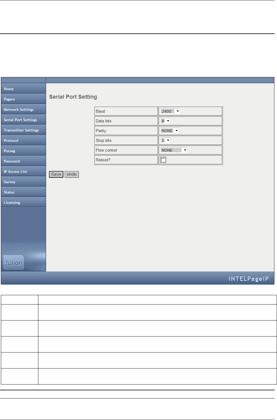
Serial Port Settings
This screen is used to edit Intelpage IP’s serial port settings.
Baud
The transmission speed of the RS232 port on the Intelpage IP (default 9600).
Data bits
The number of bits that actually contain information pertaining to the message rather than to the
transmission (e.g. stop bits). The default value is 8.
Parity
A method of verifying the accuracy of the data sent. In this case it is either none (not used), odd,
or even. The default value is NONE.
Stop bits
The number of bits sent at the end of each byte, which is used for synchronization purposes. In
this case, it is either 1 or 2. Please note that the default value is 1.
Flow
Control
This refers to the “flow control” property of the connection.
Reboot?
After making any changes to the network settings, enable this option and click the Save button to
load the new settings.
NOTE: The Intelpage IP baud, data bits, parity, and stop bits must all match that of the connected system.
Configuration
18 Installation & Configuration Guide for Intelpage IP
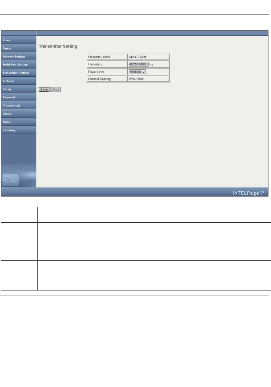
Transmitter Settings
This screen is used to edit Intelpage IP’s internal transmitter settings.
NOTE: The settings outlined on this page cannot be viewed or changed if you ordered a transmitter with the busy
detect option.
Frequency
Band
After the Intelpage IP unit has read the data from the internal transmitter, it displays the band of
the radio inside. This is either 148-174MHz or 440-470MHz.
Frequency
Here you can type the frequency required for the site in Hz. For example, if your pagers are
operating on 450.325MHz, then you would type in 450325000.
Power
Level
Use the drop down menu to toggle between low, medium, or high power levels. These values
typically correspond to power output levels of 1W, 2W, and 4W, respectively on the Intelpage IP
5.
Channel
Spacing
This field refers to the space between adjacent channels. The majority of applications use a wide
band channel, but some applications can use a narrow band channel.
Please note that after a firmware upgrade, this field is automatically populated with the correct
information for your system.
WARNING: If you have a high power 25/50/100 Watt Intelpage IP, you should not change the frequency or power
level of the unit without consulting your place of purchase. If this information is changed, the power amplifier could
be damaged.
Installation & Configuration Guide for Intelpage IP Configuration
19
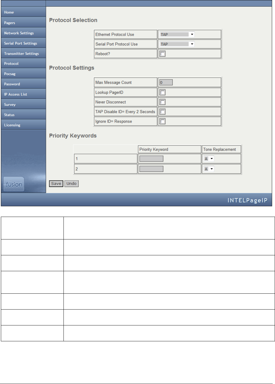
Protocol
This screen is used to edit Intelpage IP’s protocol settings.
Ethernet Protocol
Use
The protocol that the Ethernet port uses. The options available are COMP1, COMP2,
SCOPE, TAP, Terminal, TNPP, and Tekk. All the protocols use TCP port 6000 by
default; however, this port is adjustable.
Serial Port Protocol
Use
The protocol that the RS232 port (RJ45) uses. The options available are COMP1,
COMP2, SCOPE, TAP, Terminal, TNPP, and Tekk.
Reboot?
After making any changes to the protocol settings, enable this option and click the
Save button to load the new settings.
Max Msg Count
This refers to the maximum number of messages that can be sent by a protocol in a
single session/connection. A value of “0” means no maximum limit. The default value
is 0.
Lookup PagerID
If enabled, the system looks up Pager IDs in the pager database. Otherwise the system
uses the cap code supplied in the message.
Never Disconnect
If enabled, the Intelpage IP never disconnects from the remote system. It only
disconnects when the system to which it is connected disconnects.
TAP Disable ID=
every 2 seconds
If left disabled and the TAP protocol is being used, a carriage return resulting in an
“ID=” is issued every 2 seconds.

Configuration
20 Installation & Configuration Guide for Intelpage IP
Ignore ID= response
For reliable communication with certain TAP systems, such as the Teltron HPGA
Paging Gateway, this field may need to be checked. Checking this field ignores the
ID= response from the connected system so that communication does not timeout and
cause an error. The Intelpage IP must be power cycled after enabling this option. This
setting must also be used in conjunction with the “TAP Disable ID= every 2 seconds”
setting set to enabled.
Priority Keywords
Priority keywords are a useful function of Intelpage IP which allows a different beep
code to be sent if a certain word is received in a message. For example, most messages
may be sent through to users with the default beep code (tone) A. However, for
important messages containing, say the word “fire,” you might want to be sent with
the beep code D so that the users pager beeps in a different manner. In this case, you
would enter the Priority Keyword field “fire” and choose D in the Tone
Replacement field.
NOTE: The password in the TAP protocol is ignored.
Pager ID 000 must be configured for COMP1 messages.
The TNPP device address is 1234. TNPP received address is ignored. All messages are accepted.
If you are sending to a combination of numeric, alpha, and tone pagers, you need to use TNPP or SCOPE which
support various encoding formats.
Installation & Configuration Guide for Intelpage IP Configuration
21
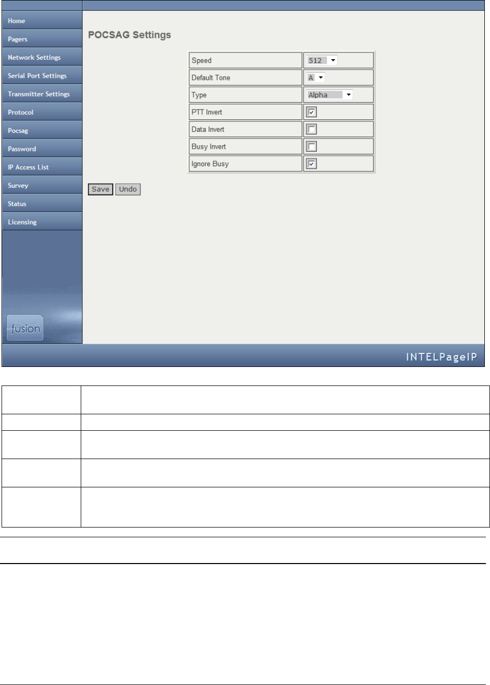
Pocsag
This screen is used to edit Intelpage IP’s POCSAG settings.
Speed
The baud rate speed of paging transmission in bps. This value must match that of the pagers
receiving the messages. The default value is 512 bps.
Default Tone
The tone type that the pager emits when the message is received. The default beep code is A.
Type
The type of message to send. Tone only, Numeric, or Alpha. This should match the type of
the pager.
PTT / Data /
Busy Invert
If disabled, these invert the respective signal. By default, PTT invert should be enabled while
Data Invert and Busy Invert should be disabled.
Ignore Busy
If enabled, the Intelpage IP sends the message regardless of whether or not the radio channel
is busy. Set this to enabled, unless you ordered an Intelpage IP specifically with the busy
detect option.
NOTE: If the SCOPE protocol is chosen, speed, tone, and type are specified along with the message and override
these POCSAG settings values.
Configuration
22 Installation & Configuration Guide for Intelpage IP
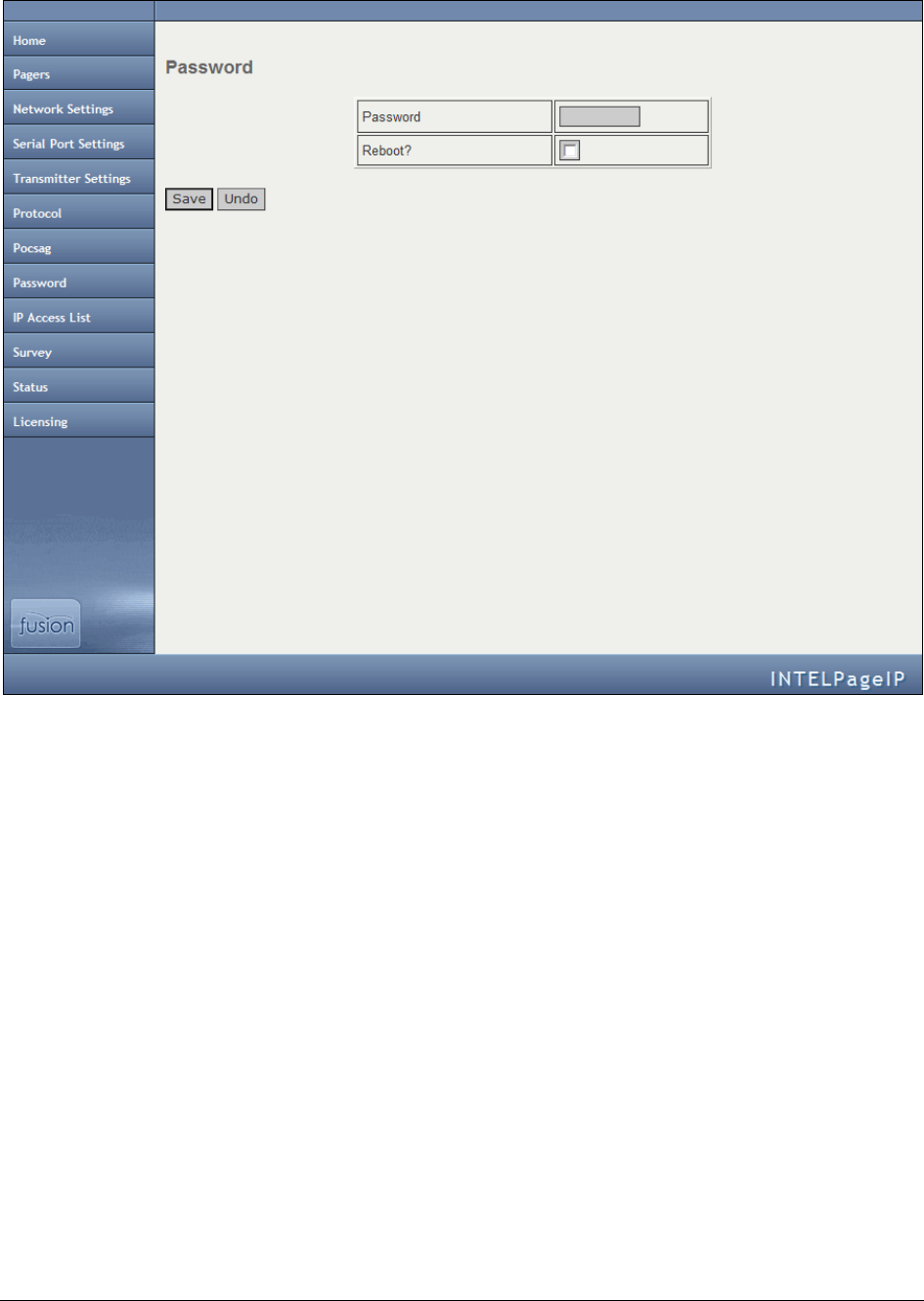
Password
This screen is used to edit the Intelpage IP’s password.
This is the password that must be entered in order to view or edit the Intelpage IP settings. It has a maximum length
of 8 characters. A reboot is needed before the new password can take effect. Please note that the default username is
“maint” without a password.
Installation & Configuration Guide for Intelpage IP Configuration
23
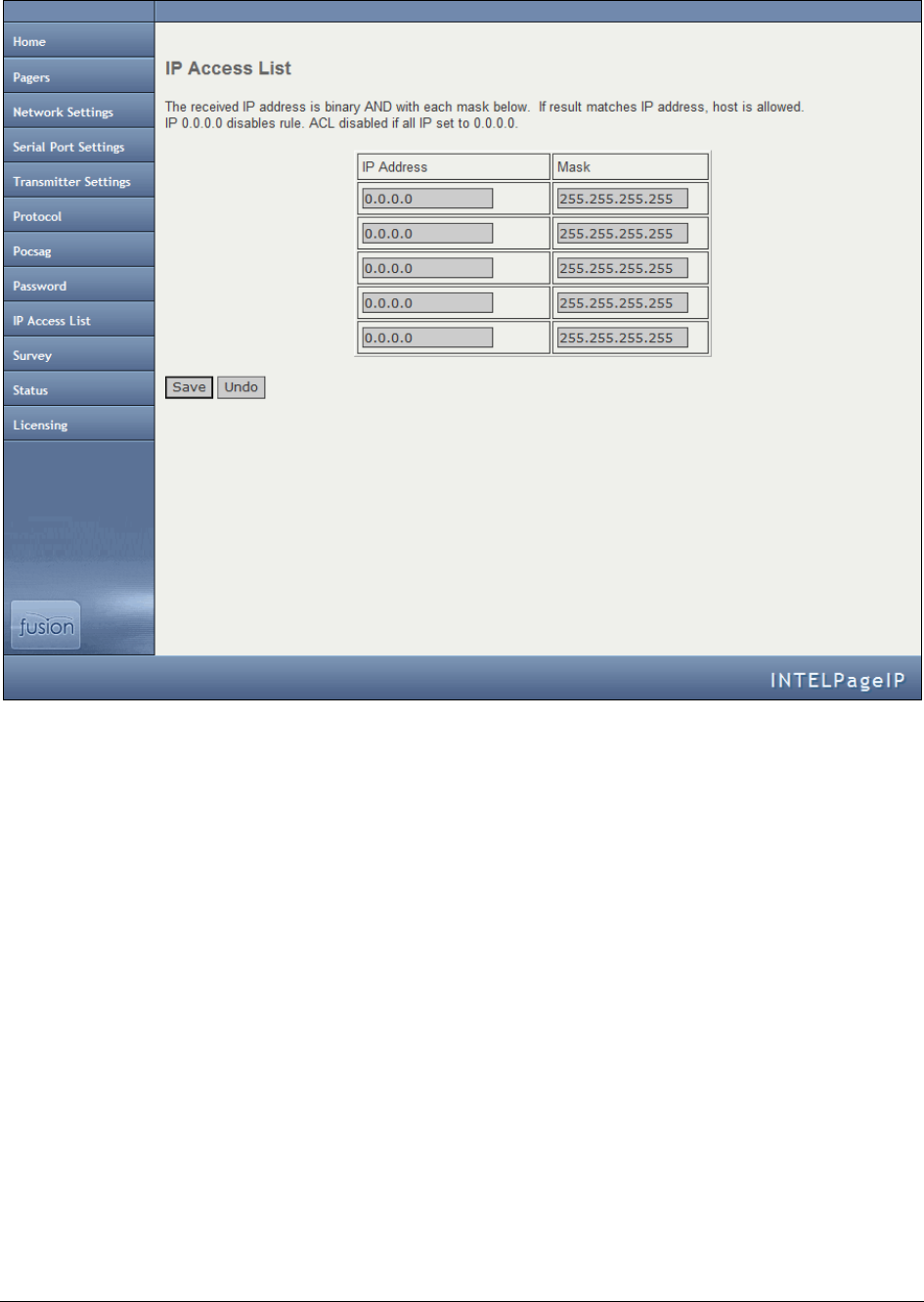
IP Access List
This screen is used to edit Intelpage IP’s firewall.
This is the list of IP addresses that are allowed to use the Intelpage IP. A received IP address is binary. If the result
matches one of the IP addresses in the control list, then the host is allowed. A brief explanation of binary and
masking can be found in the Appendix.
An IP of 0.0.0.0 disables the rule. If all IP addresses are set to 0.0.0.0, then the entire access control list (ACL) is
disabled.
Configuration
24 Installation & Configuration Guide for Intelpage IP
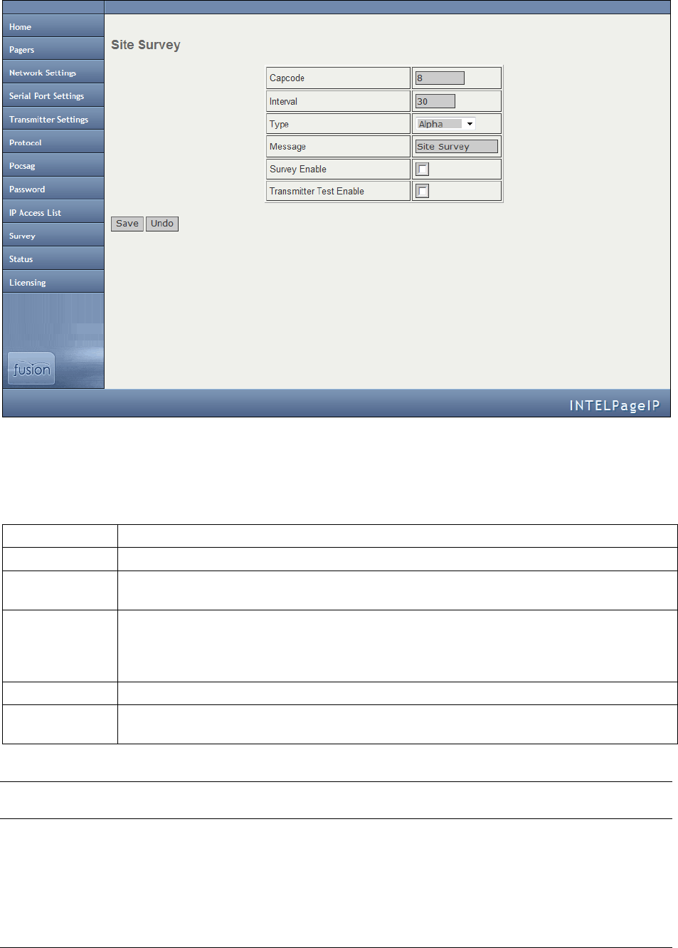
Site Survey
This screen is used to configure Intelpage IP’s site survey function.
This menu is used to test a site by sending messages periodically. One person is required for a site survey. Once you
have triggered the site survey, walk around the area intended to be covered by the transmitter making particular note
of the quality of messages received by the test pager.
Capcode
Enter the cap code of the test pager that you wish to use in the site survey.
Interval
Enter the time between test messages sent out in seconds here.
Type
Enter the encoding type used on the pager. Choose between Alpha, Numeric, Tone Only, or
Disabled.
Message
Enter the message text you would like to be sent when the site survey is performed. This text
is sent to the pager with the entered cap code every time a site survey is performed. Please
note that this field can hold a maximum of fourteen characters. The default text is “Site
Survey.”
Survey Enable
Enable this option to enable the site survey with the above settings.
Transmitter
Test Enable
Enable this option to force the transmitter to send out a constant preamble signal. This is used
when testing the transmitter on an RF test set.
NOTE: This test mode causes the transmitter to heat up rapidly. Do not use this test for extended periods of time as it
may damage the transmitter.
Installation & Configuration Guide for Intelpage IP Configuration
25
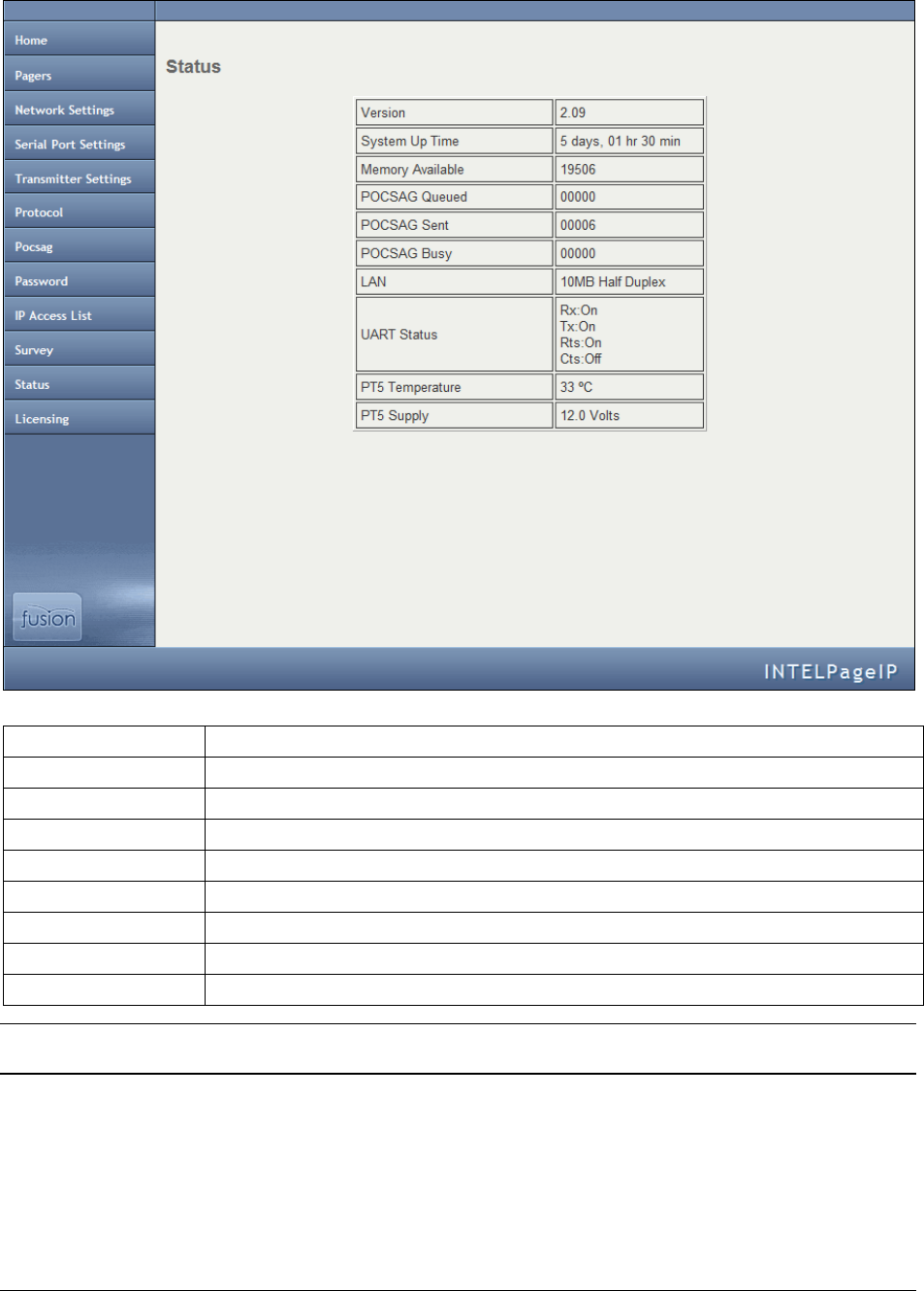
Status
The status screen shows some useful statistics about the Intelpage IP unit.
Version
The version of the firmware.
System Up Time
The duration the device has been on.
Memory Available
RAM that is available to store and send messages and server web pages.
POCSAG Queued
The number of messages that are queued and are waiting to be sent.
POCSAG Sent
The total number of messages sent since power on.
POCSAG Busy
The total number of messages that have failed to send due to the channel being busy.
UART Status
Indicates whether flow control is inhibiting the transmitting or receiving of data.
PT5 Temperature
Displays the current temperature of the internal transmitter.
PT5 Voltage
Displays the voltage that is driving the internal transmitter.
NOTE: The PT5 Temperature and PT5 Voltage fields will not be displayed if you ordered a transmitter with the
busy detect option.
Configuration
26 Installation & Configuration Guide for Intelpage IP
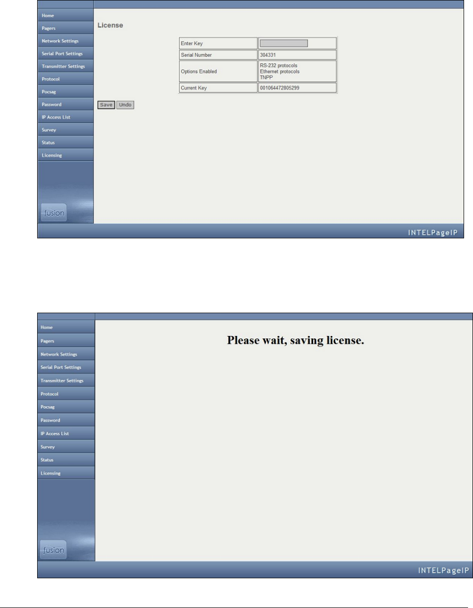
Licensing
This screen is used to configure Intelpage IP’s license key. Some of the features on the Intelpage IP can be licensed.
This means that they can be enabled or disabled by applying a new license key. License keys are generated and
provided by Amcom Software. After you obtain a license key, enter the license key into the Intelpage IP by using the
information below.
1. Choose the License menu option. The License screen displays.
2. In the Enter Key field, enter the license key that you were given.
3. Click the Save button. The following screen displays.
Installation & Configuration Guide for Intelpage IP Configuration
27
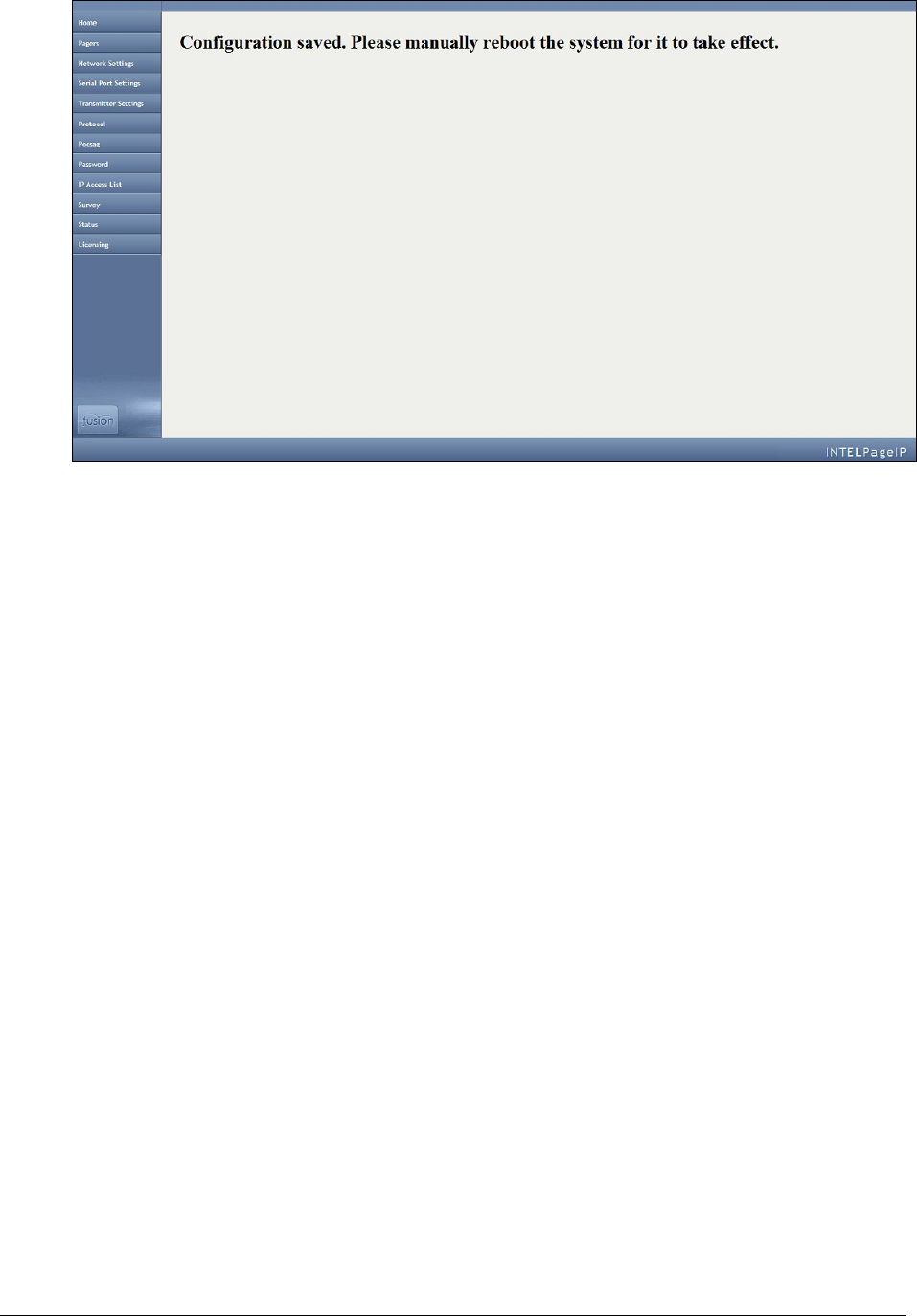
After the entered license is saved, the following screen displays.
4. Reboot your system. After your system is rebooted, the changes come into effect.
Configuration Examples
28 Installation & Configuration Guide for Intelpage IP
Configuration Examples
Configuration Examples
This section includes information on how to set up a dial-in TAP connection to the Intelpage IP from Messenger.
Setting up Dial-in TAP to Intelpage IP from Messenger
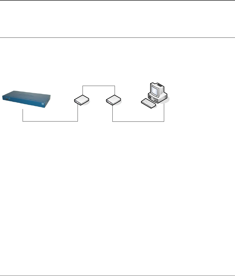
A TAP link can be created over an analog phone line between a Messenger Server or a Fusion EMM, and Intelpage
IP for remote message capability. The system is setup as described below.
Fusion Intelpage IP
Custom Cable (described below) Standard Serial Cable
Messenger or Fusion EMM
Standard Analogue Phone Line
Modem Modem
The Intelpage IP must have its RS232 port settings as follows:
Serial Port Protocol Use = TAP
Baud = 9600
Parity = None
Data bits = 8
Stop bits = 1
Flow control = None
TAP Disable ID every 2 seconds = Yes
Installation & Configuration Guide for Intelpage IP Configuration Examples
29
The modem connected to the Intelpage IP must be setup in the following way:
1. Connect this modem to a PC and use HyperTerminal (or any other communications package capable of
communicating over a serial port) to execute the commands below:
AT&F
Ensures factory default settings.
ATS0=1
Enables auto answer (after 1 ring) ATS0=2 for 2
rings, etc.
ATV0
Turn off verbose mode (Responses are 0 instead of
OK).
ATE0
Turns off local echo.
AT&W
Saves configuration to memory.
2. Power off the modem.
3. Connect the modem to the Intelpage IP unit.
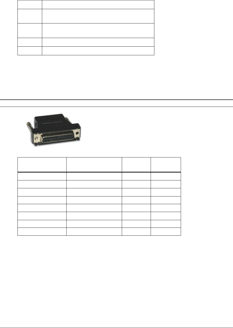
4. A customized cable is required to connect the modem to the Intelpage IP unit. The simplest way is to use a
RJ45-DB25 connector set and wire it with the following pinouts.
NOTE: If a connector set is not available, you can just make a cable with the pinouts in the table instead.
RJ45 Pin Number
On Intelpage IP
Wire Color Inside
RJ45-DB25 Adapter
Function
DB25 Pin
Number
1
2
3
Black
DTR
20
4
Red
GND
7
5
Green
RX
3
6
Yellow
TX
2
7
Brown
CTS
5
8
White
RTS
4
The modem connected to the Messenger PC must be setup in the following way:
1. Connect the modem to the PC using a standard serial cable.
2. Setup a TAP contact as normal. The default Messenger TAP gateway works for this purpose. Please note
that the telephone number must be entered into the Phone field.
3. Edit any settings, as desired.

Appendix
30 Installation & Configuration Guide for Intelpage IP
Appendix
Appendix
This section covers technical information for the Intelpage IP system, including:
Configuring Network Settings Through Terminal Interface
“Configuring Network Settings Through Terminal Interface” on page 30 includes information on how to configure
network settings through a terminal interface.
Transmitters
“Transmitters” on page 34 includes information on how to install multiple transmitters and aerials for the Intelpage
IP system.
Types of Antennas
“Types of Antennas” on page 35 includes information on the types of antennas that can be used with the Intelpage IP
system.
Technical Specifications
“Technical Specifications” on page 36 includes technical specification information for the Intelpage IP product.
Configuring Network Settings Through the Terminal
Interface
NOTE: HyperTerminal is used as the terminal emulator in this example. If it is not installed, it can be added by
changing your Windows settings. Other terminal programs such as “Putty” may be used.
1. Using the supplied black Fusion cable, connect the Intelpage IP’s COM1 RS232 port to a spare serial port
on your PC.
2. Make sure that the power is not currently plugged into the Intelpage IP unit at this stage.
3. Start HyperTerminal. It can generally be found from the Windows Start menu by choosing
Start|Programs|Accessories|Communications|HyperTerminal.
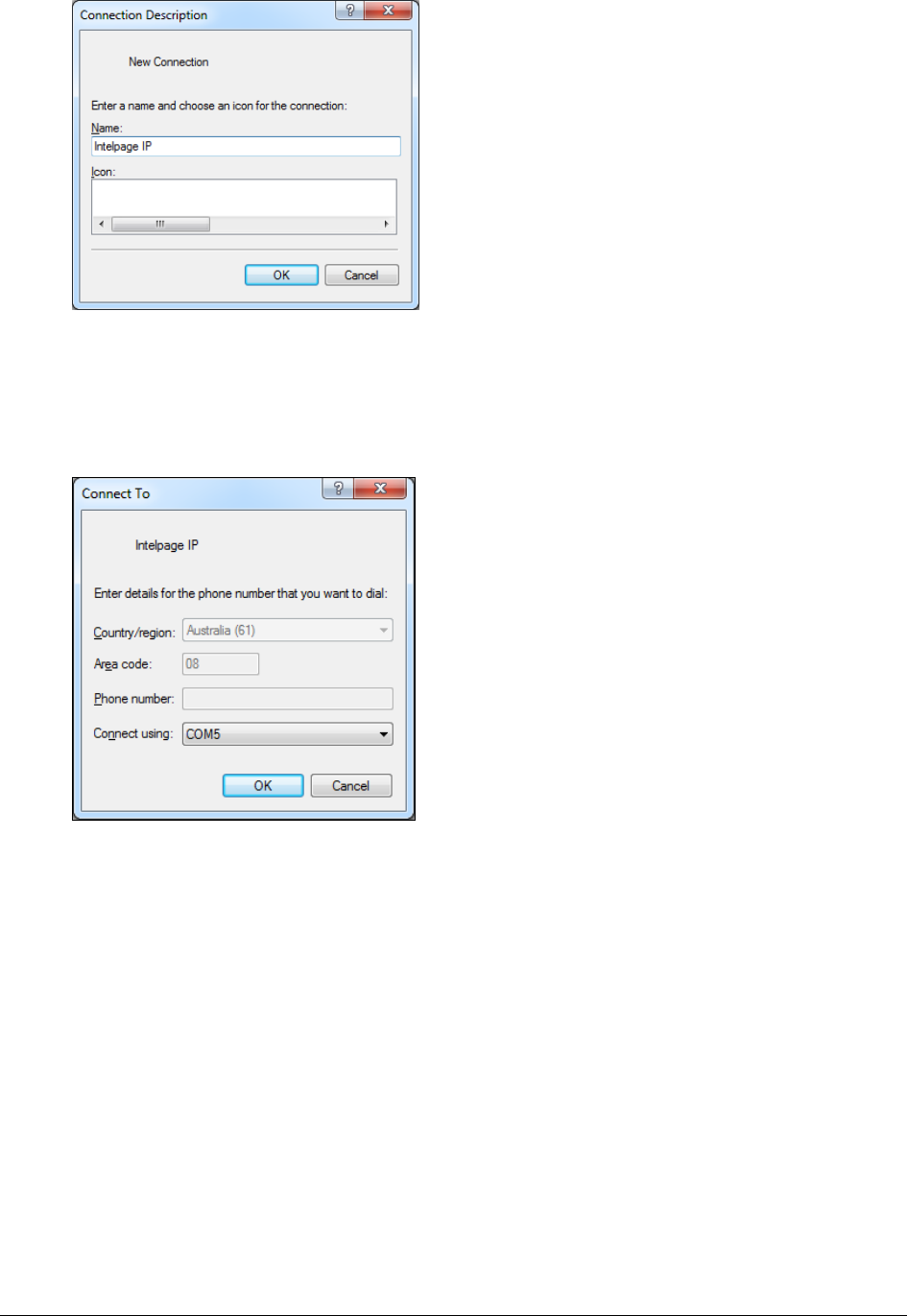
4. In the Connection Description window, add a name for the entry (such as Intelpage IP).
Installation & Configuration Guide for Intelpage IP Appendix
31
5. Click the OK button.
6. In the Connect To window, go to Connect Using.
7. Scroll to your serial port (normally COM1 or COM2). Usually, this information is written next to the serial
port on the back of the computer.
8. Click the OK button.
Appendix
32 Installation & Configuration Guide for Intelpage IP
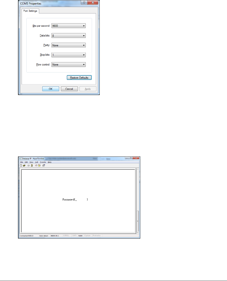
9. At the COM port properties window, click the Restore Defaults button. This automatically updates the
screen with the correct settings below.
Bits per second – Matches the Intelpage IP (default is 9600)
Data bits - 8
Parity - None
Stop bits - 1
Flow control - None
10. When the correct settings are entered, click the OK button to proceed. If no errors were encountered,
HyperTerminal displays Connected in the bottom left corner (status bar).
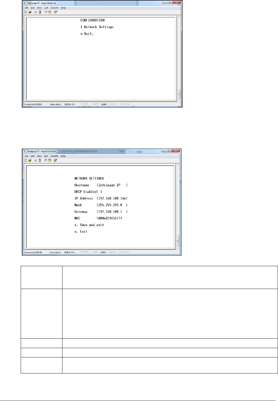
11. At this point, connect the power to the Intelpage IP unit. Within five seconds, click the Escape key four
times to bring up a password request screen as shown below.
12. By default, the password is just blank. Click Enter to proceed. If the password request screen does not
display, check the serial cable and connection settings.
Installation & Configuration Guide for Intelpage IP Appendix
33
13. From the Main menu, press the number 1 key to choose Network Settings.
14. The following screen is shown. Use the TAB or Enter key to navigate between the various fields on the
screen.
Hostname
Allows you to assign a name to the Intelpage IP on the network. This name displays in
the IPDiscover utility. Giving a unique name allows multiple IP based Fusion series
devices to be easily located and managed.
DHCP
Enabled
Click the Space Bar to enable or disable this field. By default this option is enabled,
which means that when turned on, your Intelpage IP attempts to contact a DHCP server
on the network that it is connected to in order to gain an IP Address. The supplied
IPDiscover utility can then be used to locate units on your network. In some situations,
such as if your network has no DHCP server or when interfacing with EMM,
Messenger, or TIM, the Intelpage IP may need a fixed IP address. In this case, you
need to fill in the IP Address, Mask, and Gateway fields.
IP Address
The IP address of the Intelpage IP unit.
Mask
The network mask of the network you are connected to.
Gateway
If the device needs to access the internet or another network, the gateway is the route
used to reach the external network.

Appendix
34 Installation & Configuration Guide for Intelpage IP
MAC
This is the Intelpage IP’s unique hardware number on the network. The Media Access
Control address is factory set and should not need to be changed.
NOTE: The IP Address, Mask, and Gateway fields display the current settings. If DHCP is enabled, any changes to
the fields are not saved as they are server assigned.
NOTE: Care should be taken if altering the MAC address, as it can result in the unit no longer being addressable.
15. Once configuration is complete, click the s key to save changes and return you to the Main menu.
16. The Intelpage IP should be power cycled if any changes were made to its network settings.
Transmitters
Thick steel and concrete, large magnetic and electric fields, and terrain and weather conditions affect transmitter
efficiency. Because of this, you need to test the coverage of your local area transmitter during installation.
When you perform the test, you should pay particular attention to the quality of the messages that you receive on the
test pager. If you receive corrupted messages, it is possible that you have problems sending messages to that region.
If you find that you are receiving corrupt messages, you should consider the following methods for improving
transmission quality:
Move the antenna to a position that gives it a clear line of site to all areas you wish to cover.
Reduce the length of the cable connecting the aerial to the transmitter.
Use the appropriate coaxial cable to connect the aerial to the transmitter which suits the length of the cable
run. For example, use RG213 for runs up to 20 meters and use LDF440 for runs over 20 meters.
Choose another type of antenna for the transmitter.
Position the antenna in a higher location or use an antenna with a higher gain.
Increase the transmitter power. There are a number of objections to this method, such as local restrictions on aerial
power. In addition, doubling the transmitter power to the aerial only gives an increase in range of a factor of 1:19
(fourth root).
Installing Multiple Transmitters and Aerials
For buildings in an area with good field strength outside but weak reception within, possibly caused by shielding due
to reinforcement in suspended slabs, metal plating and other building materials:
The supply lead to the aerial can serve as a radiator, effectively providing a 5 meter (yard) range from the
cable.
The supply from open (leaky) coaxial cable as a line radiator lead to a 50 terminator (the cable is in effect
the aerial).
VSWR
VSWR is a measure of impedance mismatch between the transmission line and its load. The higher the VSWR is,
the greater the mismatch. A high VSWR means some of the transmitted signal is being reflected at the antenna, back
down the coax line and back into the transmitter itself. If this value is too high, the amount of power reflected back
into the transmitter can damage the transmitter. The minimum VSWR, i.e., that which corresponds to a perfect
impedance match is 1. It is essential that the VSRW of the antenna and coax connected to the amplifier is set to 1.5
or better using a SWR meter. If this test is skipped, permanent damage may result to the amplifier. Damage also
occurs to the unit if the amplifier is set to transmit if no antenna is connected to the unit. To transmit without an
antenna connected to the unit, use a dummy load capable of handling at least that of the transmitter output.
Installation & Configuration Guide for Intelpage IP Appendix
35
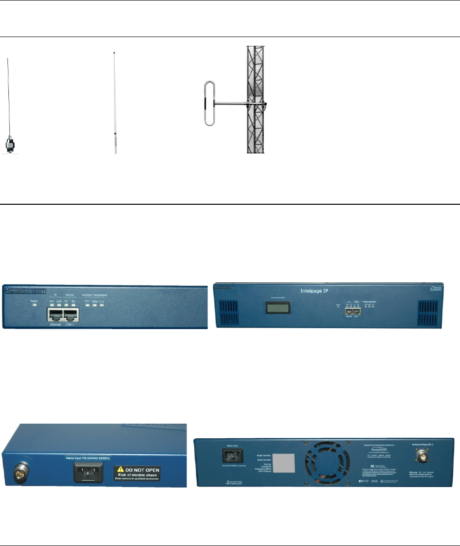
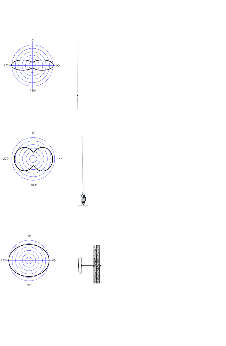
Types of Antennas
Co-linear
Co-linear antennas are most suited for installations which require maximum range. The general coverage pattern for
this type of antenna is shown below.
(Side view of site)
Mopole
Mopole antennas are most suited for installations that require good building penetration and range. It is a good
general purpose antenna. The general coverage pattern for this type of antenna is shown below.
(Side view of site)
Side Mounted / Unity Gain Dipole
Dipole antennas are most suited for installations which require excellent building penetration. The general coverage
pattern for this type of antenna is shown below.
(Side view of site)

Appendix
36 Installation & Configuration Guide for Intelpage IP
Technical Specifications
Please note that the specifications are subject to change without notice.
General
Equipment Type
IP and Serial based POCSAG paging encoder/transmitter
Frequency Range
VHF 148-174MHz. UHF 440-470MHz Synthesized
LED Indicators
Power, PTT, Data, CD (Busy), RS232 Tx, RS232 Rx, IP Activity, IP Link
External Connectors
Ethernet: RJ45F 10 Mbps
Serial: RJ45F RS232C 300-57600 Baud (default 9600bps)
Recipient Capacity
1000 pagers (with pager ID’s 0-999 available)
Supported Protocols
POCSAG 512/1200/2400bps
TAP (PET, IXO) / COMP1, 2 / SCOPE / TNPP / Terminal / Tekk (Waveware)
Duty Cycle
50%
Ambient
Temperature
Operating Range
0 to 50°C (20-90% RH non condensing)
Storage Temperature
Range
-10 to 60°C (10-95% RH non condensing)
Desktop Version Specific
Internal Transmitter
Adjustable from 100mW-5W (4W default)
Power Supply
12VDC @ 2Amps regulated via 2.1mm DC socket
Supplied with mains adapter 110-240VAC (autosensing) 50/60Hz 25W max
External Connectors
Antenna: BNC F 50Ω
Dimensions
255 x 230 x 70 mm / 10 x 8 x 2.7 inches
Weight
700g / 1.5lb nett
5 Watt Rack Version Specific
Internal Transmitter
Adjustable from 100mW-5W (4W default)
Power Supply
110-240VAC (autosensing) 50/60Hz 25W max,
Via IEC mains socket
External Connectors
Antenna: N-type F 50Ω
Dimensions
Standard 1RU 19 inch rack case
439 x 205 x 44 mm / 17.3 x 8.1 x 1.7 inches (without rack ears)
Weight
2.7kg / 5.9lb nett

Installation & Configuration Guide for Intelpage IP Appendix
37
High Power Version Specific
Internal Transmitter
25, 50 or 100W (± 10%) driven by 1-4W exciter
Power Supply
110 or 240VAC 50/60Hz 350W max,Via IEC mains socket
Henry 25W amplifier :13.8V DC nominal, 6amp maximum during transmit.
External Connectors
Antenna: N-type F 50Ω
Dimensions
Standard 2RU 19 inch rack case
439 x 430 x 88 mm / 19 x 16.5 x 3.4 inches
Weight
25 Watt unit: 7.0 kg / 15.4lb
50 Watt unit: 9.5 kg / 21.0lb
100 Watt unit: 9.5 kg / 21.0lb
Fcc Statement
This equipment has been tested and found to comply with the limits for
a Class B digital device, pursuant to Part 15 of the FCC Rules. These limits
are designed to provide reasonable protection against harmful interference
in a residential installation. This equipment generates uses and can radiate
radio frequency energy and, if not installed and used in accordance with
the instructions, may cause harmful interference to radio communications.
However, there is no guarantee that interference will not occur in a particular
installation. If this equipment does cause harmful interference to radio or
television reception, which can be determined by turning the equipment
off and on, the user is encouraged to try to correct the interference by one or
more of the following measures:
-- Reorient or relocate the receiving antenna.
-- Increase the separation between the equipment and receiver.
-- Connect the equipment into an outlet on a circuit different from that to
Which the receiver is connected. - Consult the dealer or an experienced
radio/TV technician for help
CAUTION: The antenna(s) used for this transmitter must not be co-located or operating in
conjunction with any other transmitter/antenna system. The antenna should be mounted so as to
maintain a distance of at least 89CM between the antenna and bystanders, when operated in a
typical installation and a 4 dBi antenna.