SRAM LINKED eTap System, Firmware Updated Dongle User Manual Manual
SRAM LLC. eTap System, Firmware Updated Dongle Manual
SRAM >
Manual
This is a non-approved rough
draft document. Do not share
outside of SRAM. Procedures,
illustrations, and technical
information may not be correct
and should not be used for any
service or installation.
eTap Systems
User Manual eTap Systems
User Manual eTap Systems
User Manual
eTap Systems
User Manual eTap Systems
User Manual eTap Systems
User Manual
eTap Systems
User Manual eTap Systems
User Manual eTap Systems
User Manual
eTap Systems
User Manual
95-XXXX-XXX-XXX Rev X
© 2015 SRAM, LLC
2
5 4 T25 T25 54
24 22 8 8 8
C
25 TPI
400 Grit
Grease
Tools and Supplies Tools and Supplies Tools and Supplies
Tools and Supplies Tools and Supplies Tools and Supplies
Tools and Supplies Tools and Supplies Tools and Supplies
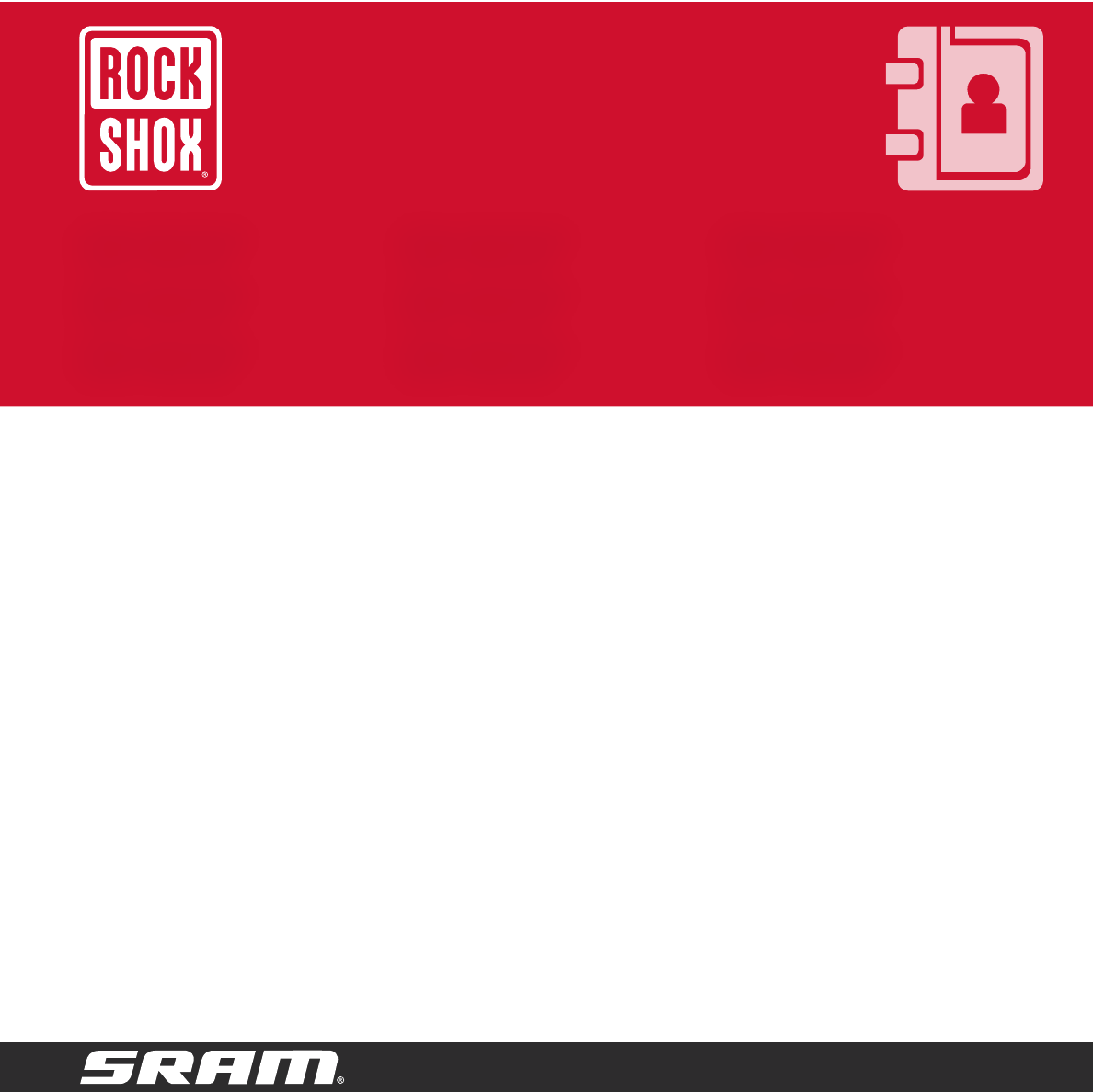
Highly specialized tools and supplies are
required for the installation of your SRAM
components. We recommend that you have
a qualified bicycle mechanic install your
SRAM components.
Highly specialized tools and supplies are
required for the installation of your SRAM
components. We recommend that you have
a qualified bicycle mechanic install your
SRAM components.
Highly specialized tools and supplies are
required for the installation of your SRAM
components. We recommend that you have
a qualified bicycle mechanic install your
SRAM components.
Highly specialized tools and supplies are
required for the installation of your SRAM
components. We recommend that you have
a qualified bicycle mechanic install your
SRAM components.
Highly specialized tools and supplies are
required for the installation of your SRAM
components. We recommend that you have
a qualified bicycle mechanic install your
SRAM components.
Highly specialized tools and supplies are
required for the installation of your SRAM
components. We recommend that you have
a qualified bicycle mechanic install your
SRAM components.
Highly specialized tools and supplies are
required for the installation of your SRAM
components. We recommend that you have
a qualified bicycle mechanic install your
SRAM components.
Highly specialized tools and supplies are
required for the installation of your SRAM
components. We recommend that you have
a qualified bicycle mechanic install your
SRAM components.
Highly specialized tools and supplies are
required for the installation of your SRAM
components. We recommend that you have
a qualified bicycle mechanic install your
SRAM components.

3
SAFETY INSTRUCTIONS
You must read and understand
the safety and warranty document
before proceeding with installation.
Improperly installed components are
extremely dangerous and can result in
severe and/or fatal injuries. If you have
any questions on the installation of
these parts, consult a qualified bicycle
mechanic. This document is also
available on www.sram.com.
4
Battery Charging Battery Charging Battery Charging
Battery Charging Battery Charging Battery Charging
Battery Charging Battery Charging Battery Charging
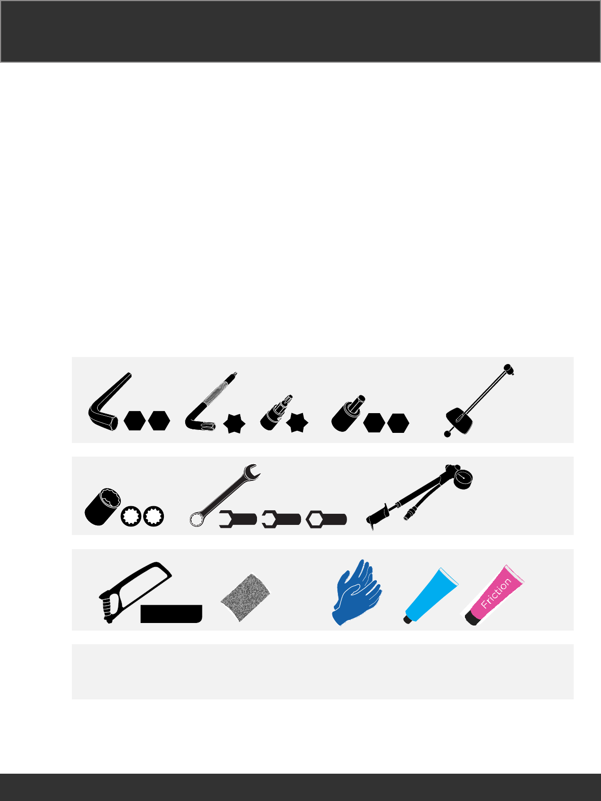
Remove the battery cover from the
battery.
NOTICE
Do not discard the derailleur battery
cover. Install the derailleur battery
cover on the battery when it is not on
the charger or derailleur.
Remove the battery cover from the
battery.
NOTICE
Do not discard the derailleur battery
cover. Install the derailleur battery
cover on the battery when it is not on
the charger or derailleur.
Remove the battery cover from the
battery.
NOTICE
Do not discard the derailleur battery
cover. Install the derailleur battery
cover on the battery when it is not on
the charger or derailleur.
Remove the battery cover from the
battery.
NOTICE
Do not discard the derailleur battery
cover. Install the derailleur battery
cover on the battery when it is not on
the charger or derailleur.
Remove the battery cover from the
battery.
NOTICE
Do not discard the derailleur battery
cover. Install the derailleur battery
cover on the battery when it is not on
the charger or derailleur.
Remove the battery cover from the
battery.
NOTICE
Do not discard the derailleur battery
cover. Install the derailleur battery
cover on the battery when it is not on
the charger or derailleur.
Remove the battery cover from the
battery.
NOTICE
Do not discard the derailleur battery
cover. Install the derailleur battery
cover on the battery when it is not on
the charger or derailleur.
Remove the battery cover from the
battery.
NOTICE
Do not discard the derailleur battery
cover. Install the derailleur battery
cover on the battery when it is not on
the charger or derailleur.
Remove the battery cover from the
battery.
NOTICE
Do not discard the derailleur battery
cover. Install the derailleur battery
cover on the battery when it is not on
the charger or derailleur.
1
2
4
3
Remove Retirer Retire
Entfernen Rimuovere
Quitar Verwijderen
Install Installer Instalar
Einbauen Installare
Instalación Monteren
Adjust Régler Ajustar
Einstellen Regolare
Ajustar Afstellen

5
Install the battery into the charger with
the battery foot seated in the base
first.
The LED lights are amber while the
battery is charging and turns green
when the charging is complete.
Install the battery into the charger with
the battery foot seated in the base
first.
The LED lights are amber while the
battery is charging and turns green
when the charging is complete.
Install the battery into the charger with
the battery foot seated in the base
first.
The LED lights are amber while the
battery is charging and turns green
when the charging is complete.
Install the battery into the charger with
the battery foot seated in the base
first.
The LED lights are amber while the
battery is charging and turns green
when the charging is complete.
Install the battery into the charger with
the battery foot seated in the base
first.
The LED lights are amber while the
battery is charging and turns green
when the charging is complete.
Install the battery into the charger with
the battery foot seated in the base
first.
The LED lights are amber while the
battery is charging and turns green
when the charging is complete.
Install the battery into the charger with
the battery foot seated in the base
first.
The LED lights are amber while the
battery is charging and turns green
when the charging is complete.
Install the battery into the charger with
the battery foot seated in the base
first.
The LED lights are amber while the
battery is charging and turns green
when the charging is complete.
Install the battery into the charger with
the battery foot seated in the base
first.
The LED lights are amber while the
battery is charging and turns green
when the charging is complete.
1
2
4
3
Remove Retirer Retire
Entfernen Rimuovere
Quitar Verwijderen
Install Installer Instalar
Einbauen Installare
Instalación Monteren
Adjust Régler Ajustar
Einstellen Regolare
Ajustar Afstellen

6
Press the button on the charger base
to release the battery.
NOTICE
Immediately install the derailleur
battery cover or install the battery
on the derailleur. Failure to cover the
battery connection points could result
in damage to the battery.
Press the button on the charger base
to release the battery.
NOTICE
Immediately install the derailleur
battery cover or install the battery
on the derailleur. Failure to cover the
battery connection points could result
in damage to the battery.
Press the button on the charger base
to release the battery.
NOTICE
Immediately install the derailleur
battery cover or install the battery
on the derailleur. Failure to cover the
battery connection points could result
in damage to the battery.
Press the button on the charger base
to release the battery.
NOTICE
Immediately install the derailleur
battery cover or install the battery
on the derailleur. Failure to cover the
battery connection points could result
in damage to the battery.
Press the button on the charger base
to release the battery.
NOTICE
Immediately install the derailleur
battery cover or install the battery
on the derailleur. Failure to cover the
battery connection points could result
in damage to the battery.
Press the button on the charger base
to release the battery.
NOTICE
Immediately install the derailleur
battery cover or install the battery
on the derailleur. Failure to cover the
battery connection points could result
in damage to the battery.
Press the button on the charger base
to release the battery.
NOTICE
Immediately install the derailleur
battery cover or install the battery
on the derailleur. Failure to cover the
battery connection points could result
in damage to the battery.
Press the button on the charger base
to release the battery.
NOTICE
Immediately install the derailleur
battery cover or install the battery
on the derailleur. Failure to cover the
battery connection points could result
in damage to the battery.
Press the button on the charger base
to release the battery.
NOTICE
Immediately install the derailleur
battery cover or install the battery
on the derailleur. Failure to cover the
battery connection points could result
in damage to the battery.
1
2
4
3
Remove Retirer Retire
Entfernen Rimuovere
Quitar Verwijderen
Install Installer Instalar
Einbauen Installare
Instalación Monteren
Adjust Régler Ajustar
Einstellen Regolare
Ajustar Afstellen
7
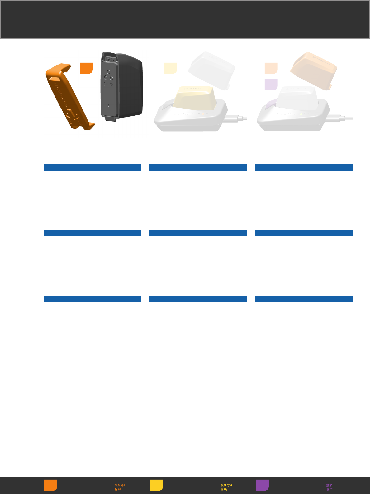
Begin the pairing session
at the rear derailleur. Press
and hold the function button
on the rear derailleur until
the green LED blinks slowly,
then release.
Begin the pairing session
at the rear derailleur. Press
and hold the function button
on the rear derailleur until
the green LED blinks slowly,
then release.
Begin the pairing session
at the rear derailleur. Press
and hold the function button
on the rear derailleur until
the green LED blinks slowly,
then release.
Begin the pairing session
at the rear derailleur. Press
and hold the function button
on the rear derailleur until
the green LED blinks slowly,
then release.
Begin the pairing session
at the rear derailleur. Press
and hold the function button
on the rear derailleur until
the green LED blinks slowly,
then release.
Begin the pairing session
at the rear derailleur. Press
and hold the function button
on the rear derailleur until
the green LED blinks slowly,
then release.
Begin the pairing session
at the rear derailleur. Press
and hold the function button
on the rear derailleur until
the green LED blinks slowly,
then release.
Begin the pairing session
at the rear derailleur. Press
and hold the function button
on the rear derailleur until
the green LED blinks slowly,
then release.
Begin the pairing session
at the rear derailleur. Press
and hold the function button
on the rear derailleur until
the green LED blinks slowly,
then release.
System Pairing System Pairing System Pairing
System Pairing System Pairing System Pairing
System Pairing System Pairing System Pairing
Install
Einbauen
Instalación
Installer
Installare
Monteren
Instalar
NOTICE
The rear derailleur is the master device,
and the pairing session begins with
the master device. The LED on the rear
derailleur and the device being paired
will blink quickly when the device is
successfully paired.
Steps 2-4 can be done in any order.
The rear derailleur LED light will blink
when it has received and executed a
command.
NOTICE
The rear derailleur is the master
device, and the pairing session begins
with the master device. The LED on
the rear derailleur and the device
being paired will blink quickly when
the device is successfully paired.
Steps 2-4 can be done in any order.
The rear derailleur LED light will blink
when it has received and executed a
command.
NOTICE
The rear derailleur is the master device,
and the pairing session begins with
the master device. The LED on the rear
derailleur and the device being paired
will blink quickly when the device is
successfully paired.
Steps 2-4 can be done in any order.
The rear derailleur LED light will blink
when it has received and executed a
command.
NOTICE
The rear derailleur is the master
device, and the pairing session begins
with the master device. The LED on
the rear derailleur and the device
being paired will blink quickly when
the device is successfully paired.
Steps 2-4 can be done in any order.
The rear derailleur LED light will blink
when it has received and executed a
command.
NOTICE
The rear derailleur is the master device,
and the pairing session begins with
the master device. The LED on the rear
derailleur and the device being paired
will blink quickly when the device is
successfully paired.
Steps 2-4 can be done in any order.
The rear derailleur LED light will blink
when it has received and executed a
command.
1
8
Remove
Entfernen
Quitar
Retirer
Rimuovere
Verwijderen
Retire
Measure
Messen
Medir
Mesurer
Misurare
Meten
Medir
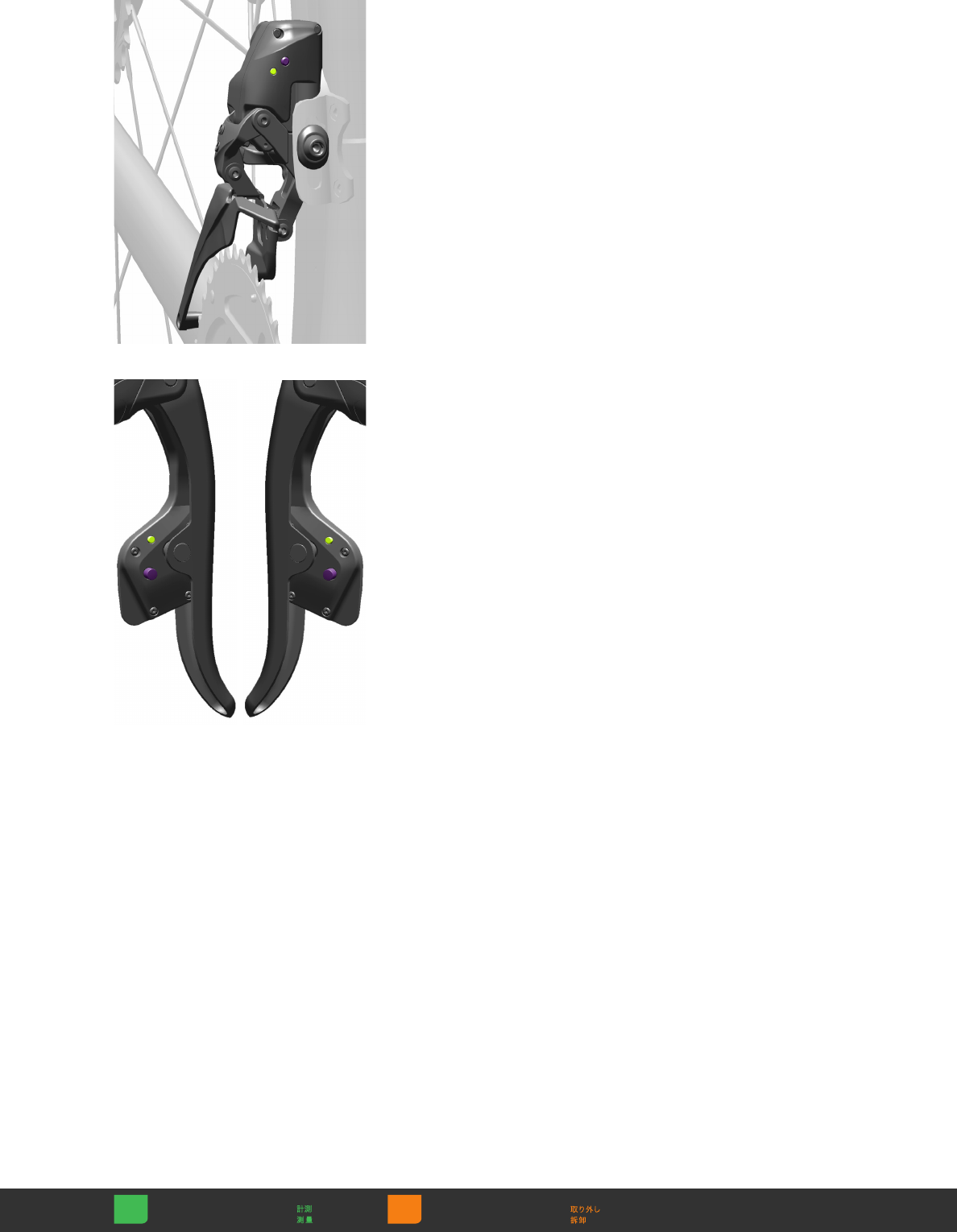
Press and hold the function
button on one shifter
until the green LED blinks
quickly, then release.
Repeat on the other shifter.
Press and hold the function
button on one shifter
until the green LED blinks
quickly, then release.
Repeat on the other shifter.
Press and hold the function
button on one shifter
until the green LED blinks
quickly, then release.
Repeat on the other shifter.
Press and hold the function
button on one shifter
until the green LED blinks
quickly, then release.
Repeat on the other shifter.
Press and hold the function
button on one shifter
until the green LED blinks
quickly, then release.
Repeat on the other shifter.
Press and hold the function
button on one shifter
until the green LED blinks
quickly, then release.
Repeat on the other shifter.
Press and hold the function
button on one shifter
until the green LED blinks
quickly, then release.
Repeat on the other shifter.
Press and hold the function
button on one shifter
until the green LED blinks
quickly, then release.
Repeat on the other shifter.
Press and hold the function
button on one shifter
until the green LED blinks
quickly, then release.
Repeat on the other shifter.
Press and hold the function
button on the front
derailleur until the green
LED blinks quickly, then
release.
Press and hold the function
button on the front
derailleur until the green
LED blinks quickly, then
release.
Press and hold the function
button on the front
derailleur until the green
LED blinks quickly, then
release.
Press and hold the function
button on the front
derailleur until the green
LED blinks quickly, then
release.
Press and hold the function
button on the front
derailleur until the green
LED blinks quickly, then
release.
Press and hold the function
button on the front
derailleur until the green
LED blinks quickly, then
release.
Press and hold the function
button on the front
derailleur until the green
LED blinks quickly, then
release.
Press and hold the function
button on the front
derailleur until the green
LED blinks quickly, then
release.
Press and hold the function
button on the front
derailleur until the green
LED blinks quickly, then
release.
Press and release the
function button on the rear
derailleur to end pairing,
or wait 30 seconds for the
pairing session to time out.
The green LED will stop
blinking.
Press and release the
function button on the rear
derailleur to end pairing,
or wait 30 seconds for the
pairing session to time out.
The green LED will stop
blinking.
Press and release the
function button on the rear
derailleur to end pairing,
or wait 30 seconds for the
pairing session to time out.
The green LED will stop
blinking.
Press and release the
function button on the rear
derailleur to end pairing,
or wait 30 seconds for the
pairing session to time out.
The green LED will stop
blinking.
Press and release the
function button on the rear
derailleur to end pairing,
or wait 30 seconds for the
pairing session to time out.
The green LED will stop
blinking.
Press and release the
function button on the rear
derailleur to end pairing,
or wait 30 seconds for the
pairing session to time out.
The green LED will stop
blinking.
Press and release the
function button on the rear
derailleur to end pairing,
or wait 30 seconds for the
pairing session to time out.
The green LED will stop
blinking.
Press and release the
function button on the rear
derailleur to end pairing,
or wait 30 seconds for the
pairing session to time out.
The green LED will stop
blinking.
Press and release the
function button on the rear
derailleur to end pairing,
or wait 30 seconds for the
pairing session to time out.
The green LED will stop
blinking.

9
NOTICE
Any time a new device is added,
the entire pairing process must be
repeated for all devices. For example, if
the right shifter is replaced, the entire
system will need to be paired again.
NOTICE
Any time a new device is added,
the entire pairing process must be
repeated for all devices. For example, if
the right shifter is replaced, the entire
system will need to be paired again.
NOTICE
Any time a new device is added,
the entire pairing process must be
repeated for all devices. For example, if
the right shifter is replaced, the entire
system will need to be paired again.
NOTICE
Any time a new device is added,
the entire pairing process must be
repeated for all devices. For example, if
the right shifter is replaced, the entire
system will need to be paired again.
NOTICE
Any time a new device is added,
the entire pairing process must be
repeated for all devices. For example, if
the right shifter is replaced, the entire
system will need to be paired again.
NOTICE
Any time a new device is added,
the entire pairing process must be
repeated for all devices. For example, if
the right shifter is replaced, the entire
system will need to be paired again.
NOTICE
Any time a new device is added,
the entire pairing process must be
repeated for all devices. For example, if
the right shifter is replaced, the entire
system will need to be paired again.
NOTICE
Any time a new device is added,
the entire pairing process must be
repeated for all devices. For example, if
the right shifter is replaced, the entire
system will need to be paired again.
NOTICE
Any time a new device is added,
the entire pairing process must be
repeated for all devices. For example, if
the right shifter is replaced, the entire
system will need to be paired again.
Verify the system is paired
by shifting the derailleurs
in both directions. If the
derailleurs do not respond,
repeat the pairing process.
Verify the system is paired
by shifting the derailleurs
in both directions. If the
derailleurs do not respond,
repeat the pairing process.
Verify the system is paired
by shifting the derailleurs
in both directions. If the
derailleurs do not respond,
repeat the pairing process.
Verify the system is paired
by shifting the derailleurs
in both directions. If the
derailleurs do not respond,
repeat the pairing process.
Verify the system is paired
by shifting the derailleurs
in both directions. If the
derailleurs do not respond,
repeat the pairing process.
Verify the system is paired
by shifting the derailleurs
in both directions. If the
derailleurs do not respond,
repeat the pairing process.
Verify the system is paired
by shifting the derailleurs
in both directions. If the
derailleurs do not respond,
repeat the pairing process.
Verify the system is paired
by shifting the derailleurs
in both directions. If the
derailleurs do not respond,
repeat the pairing process.
Verify the system is paired
by shifting the derailleurs
in both directions. If the
derailleurs do not respond,
repeat the pairing process.
10
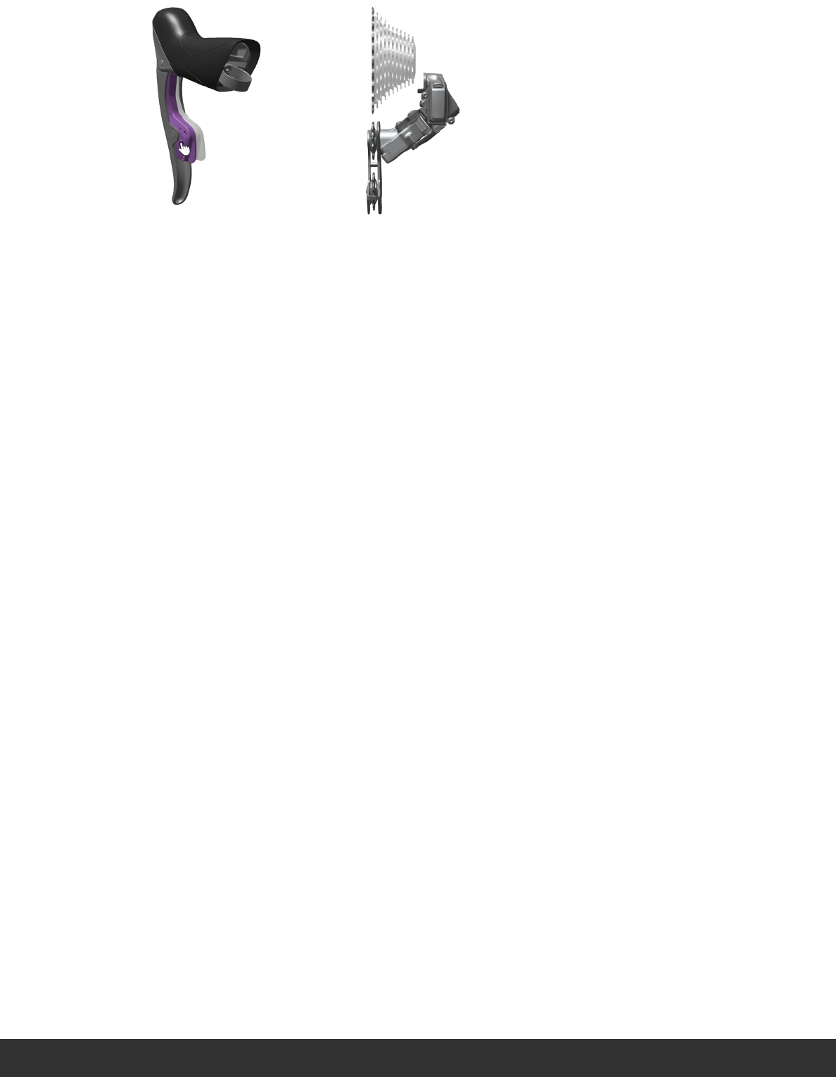
Shifting Shifting Shifting
Shifting Shifting Shifting
Shifting Shifting Shifting
1
2
Press the left shifter paddle to move the
rear derailleur inboard. Press and hold the
paddle for multiple shifts.
Press the left shifter paddle to move the
rear derailleur inboard. Press and hold the
paddle for multiple shifts.
Press the left shifter paddle to move the
rear derailleur inboard. Press and hold the
paddle for multiple shifts.
Press the left shifter paddle to move the
rear derailleur inboard. Press and hold the
paddle for multiple shifts.
Press the left shifter paddle to move the
rear derailleur inboard. Press and hold the
paddle for multiple shifts.
Press the left shifter paddle to move the
rear derailleur inboard. Press and hold the
paddle for multiple shifts.
Press the left shifter paddle to move the
rear derailleur inboard. Press and hold the
paddle for multiple shifts.
Press the left shifter paddle to move the
rear derailleur inboard. Press and hold the
paddle for multiple shifts.
Press the left shifter paddle to move the
rear derailleur inboard. Press and hold the
paddle for multiple shifts.
Press the right shifter paddle to move the
rear derailleur outboard. Press and hold the
paddle for multiple shifts.
Press the right shifter paddle to move the
rear derailleur outboard. Press and hold the
paddle for multiple shifts.
Press the right shifter paddle to move the
rear derailleur outboard. Press and hold the
paddle for multiple shifts.
Press the right shifter paddle to move the
rear derailleur outboard. Press and hold the
paddle for multiple shifts.
Press the right shifter paddle to move the
rear derailleur outboard. Press and hold the
paddle for multiple shifts.
Press the right shifter paddle to move the
rear derailleur outboard. Press and hold the
paddle for multiple shifts.
Press the right shifter paddle to move the
rear derailleur outboard. Press and hold the
paddle for multiple shifts.
Press the right shifter paddle to move the
rear derailleur outboard. Press and hold the
paddle for multiple shifts.
Press the right shifter paddle to move the
rear derailleur outboard. Press and hold the
paddle for multiple shifts.

11
3
Press both shifter paddles simultaneously
to move the front derailleur inboard or
outboard.
Press both shifter paddles simultaneously
to move the front derailleur inboard or
outboard.
Press both shifter paddles simultaneously
to move the front derailleur inboard or
outboard.
Press both shifter paddles simultaneously
to move the front derailleur inboard or
outboard.
Press both shifter paddles simultaneously
to move the front derailleur inboard or
outboard.
Press both shifter paddles simultaneously
to move the front derailleur inboard or
outboard.
Press both shifter paddles simultaneously
to move the front derailleur inboard or
outboard.
Press both shifter paddles simultaneously
to move the front derailleur inboard or
outboard.
Press both shifter paddles simultaneously
to move the front derailleur inboard or
outboard.
12
Torque
Drehmoment
Momento
Valeur de couple
Coppia
Aandraaimoment
Momento de torção
Install
Einbauen
Instalación
Installer
Installare
Monteren
Instalar
Measure
Messen
Medir
Mesurer
Misurare
Meten
Medir
Shifter Installation Shifter Installation Shifter Installation
Shifter Installation Shifter Installation Shifter Installation
Shifter Installation Shifter Installation Shifter Installation
2
5
6-8 N·m
(53-70 in-lb)
+
3
4
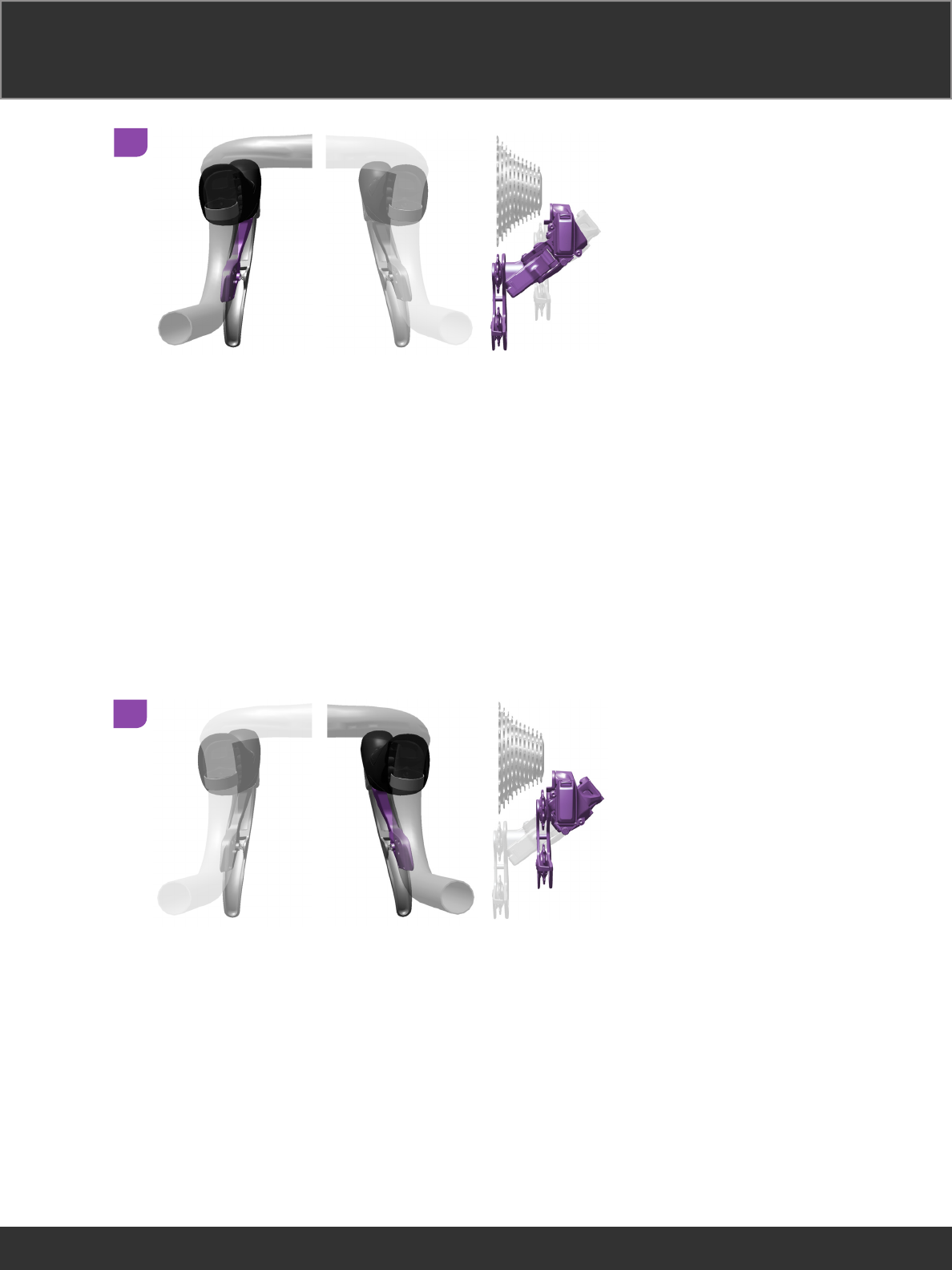
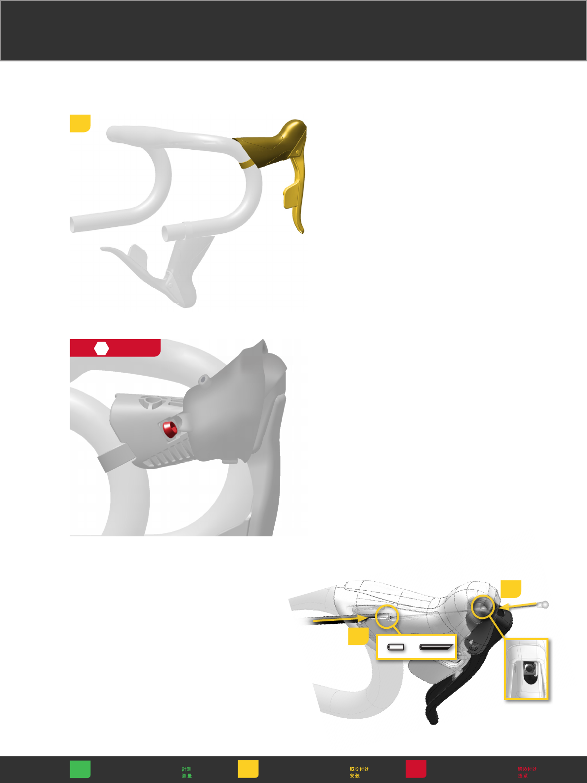
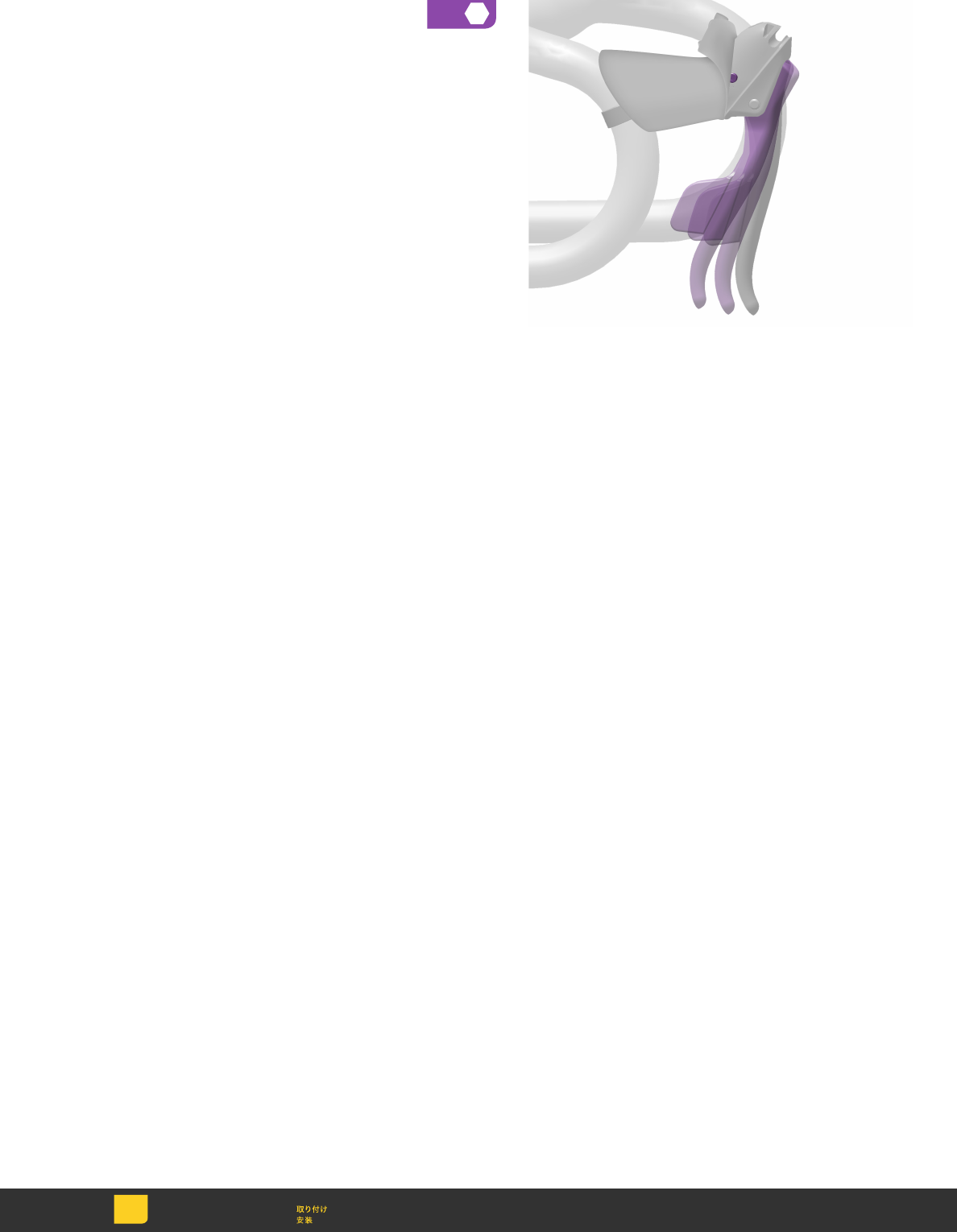
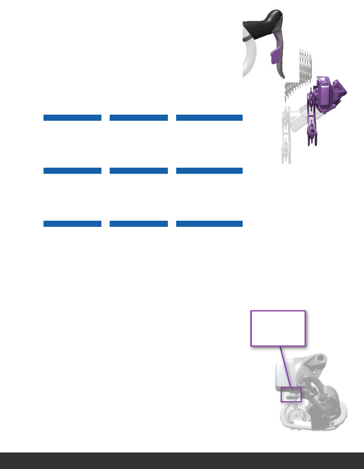
Install the shifter
assembly onto
the handlebar
and set it to your
desired position.
Install the shifter
assembly onto
the handlebar
and set it to your
desired position.
Install the shifter
assembly onto
the handlebar
and set it to your
desired position.
Install the shifter
assembly onto
the handlebar
and set it to your
desired position.
Install the shifter
assembly onto
the handlebar
and set it to your
desired position.
Install the shifter
assembly onto
the handlebar
and set it to your
desired position.
Install the shifter
assembly onto
the handlebar
and set it to your
desired position.
Install the shifter
assembly onto
the handlebar
and set it to your
desired position.
Install the shifter
assembly onto
the handlebar
and set it to your
desired position.
Use a 5 mm hex
bit socket to
torque the shifter
bolt to 6-8 N·m
(53-70 in-lbs).
Use a 5 mm hex
bit socket to
torque the shifter
bolt to 6-8 N·m
(53-70 in-lbs).
Use a 5 mm hex
bit socket to
torque the shifter
bolt to 6-8 N·m
(53-70 in-lbs).
Use a 5 mm
hex bit socket
to torque thte
shifter bolt to 6-8
N·m
(53-70 in-lbs).
Use a 5 mm hex
bit socket to
torque the shifter
bolt to 6-8 N·m
(53-70 in-lbs).
Use a 5 mm hex
bit socket to
torque the shifter
bolt to 6-8 N·m
(53-70 in-lbs).
Use a 5 mm hex
bit socket to
torque the shifter
bolt to 6-8 N·m
(53-70 in-lbs).
Use a 5 mm hex
bit socket to
torque the shifter
bolt to 6-8 N·m
(53-70 in-lbs).
Use a 5 mm hex
bit socket to
torque the shifter
bolt to 6-8 N·m
(53-70 in-lbs).
1
2
5
6-8 N·m
(53-70 in-lb)
13
Install
Einbauen
Instalación
Installer
Installare
Monteren
Instalar
5
2.5
14
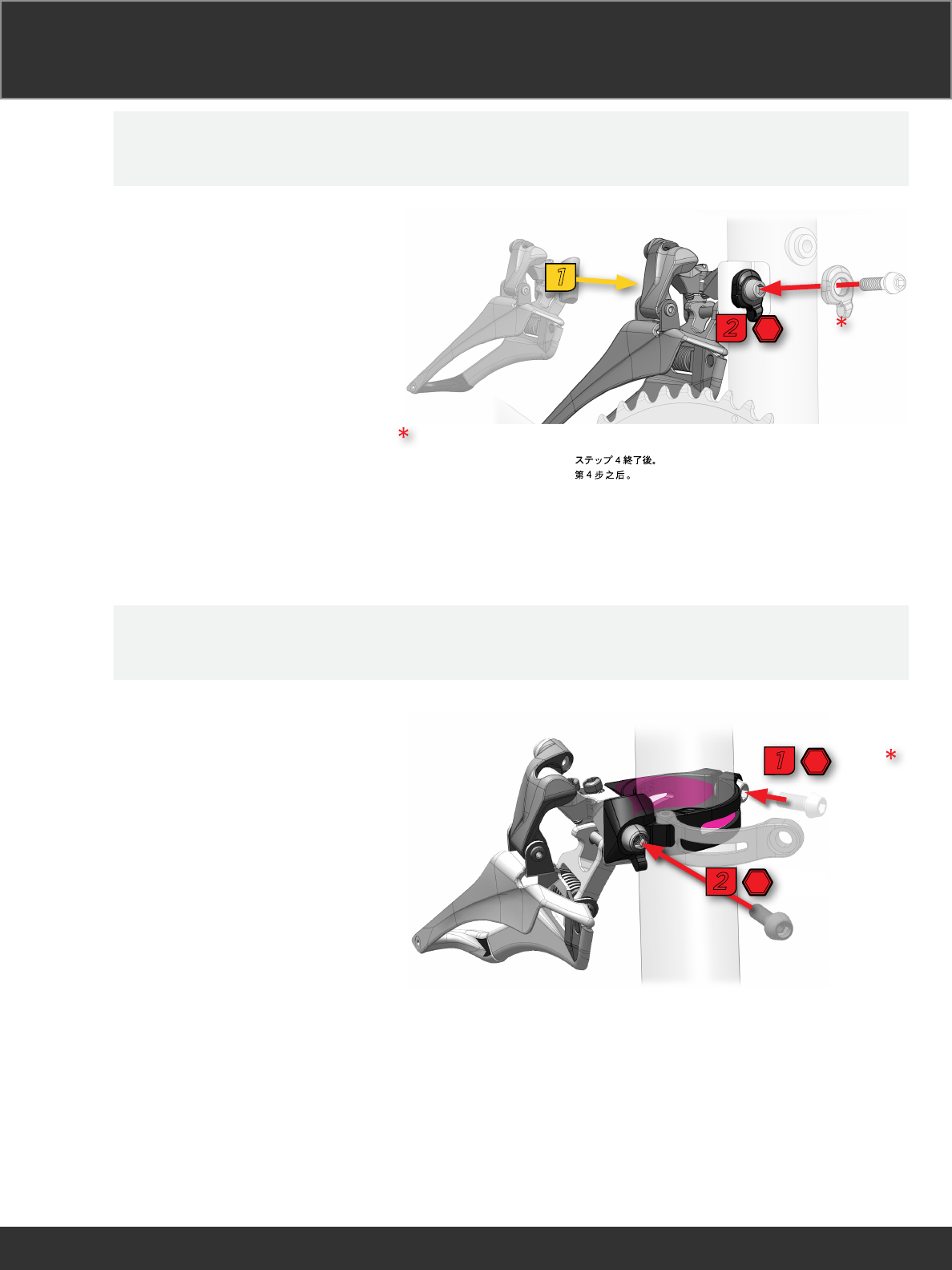
Front Derailleur Installation Front Derailleur Installation Front Derailleur Installation
Front Derailleur Installation Front Derailleur Installation Front Derailleur Installation
Front Derailleur Installation Front Derailleur Installation Front Derailleur Installation
Direct Mount Direct Mount Direct Mount
Direct Mount Direct Mount Direct Mount
Direct Mount Direct Mount Direct Mount
Clamp Mount Clamp Mount Clamp Mount
Clamp Mount Clamp Mount Clamp Mount
Clamp Mount Clamp Mount Clamp Mount
5-7 N·m (44-62 in-lb)
1
4
5-7 N·m
(44-62 in-lb)
2
4
1
After step 4.
Nach Schritt 4.
Después del paso 4.
Après l’étape 4.
Dopo il punto 4.
Na stap 4.
Depois do passo 4.
Po kroku 4.
Efter trin 4.
Po provedení kroku 4.
Μετά το βήμα 4.
După pasul 4.
4-5 N·m
(35-44 in-lb)
1
4
5-7 N·m
(44-62 in-lb)
2
4
15
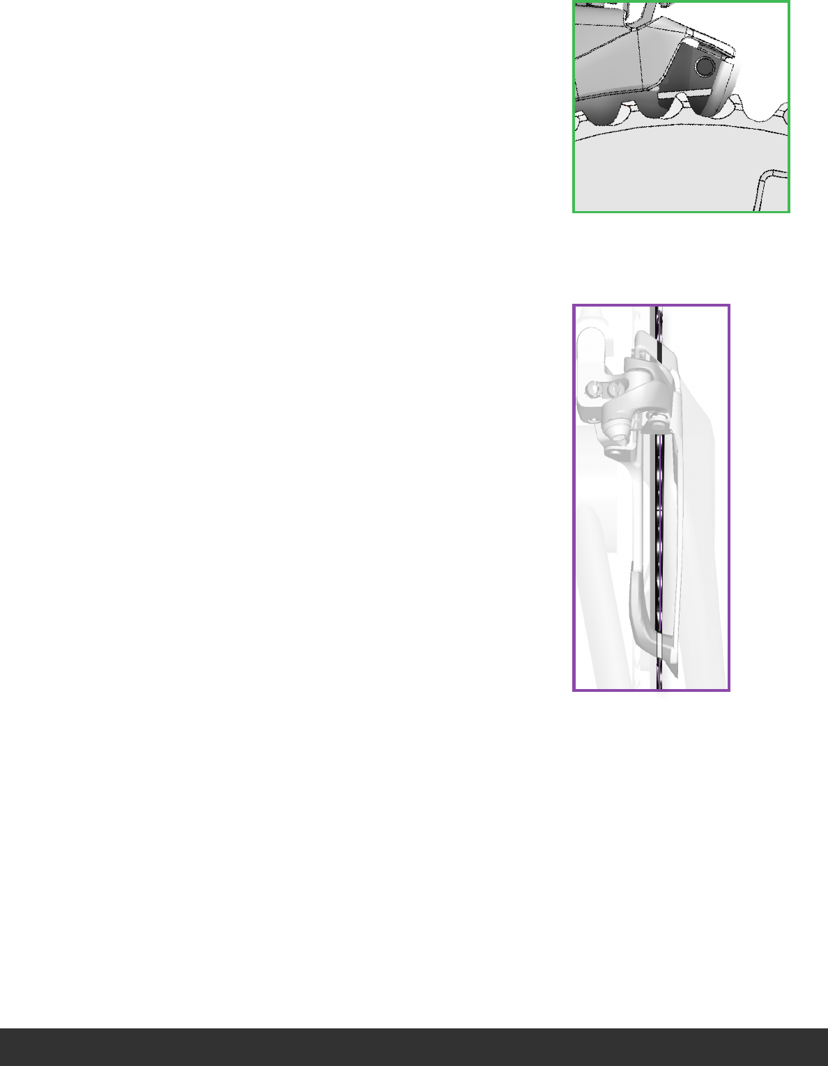
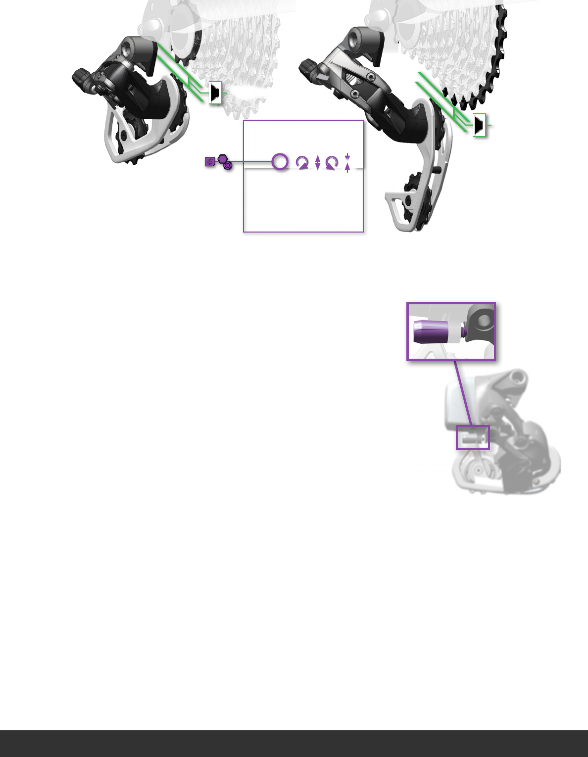
The tip of the tallest
chainring teeth must
appear within the
setup line when viewed
directly from the side.
The tip of the tallest
chainring teeth must
appear within the
setup line when viewed
directly from the side.
The tip of the tallest
chainring teeth must
appear within the
setup line when viewed
directly from the side.
The tip of the tallest
chainring teeth must
appear within the
setup line when viewed
directly from the side.
The tip of the tallest
chainring teeth must
appear within the
setup line when viewed
directly from the side.
The tip of the tallest
chainring teeth must
appear within the
setup line when viewed
directly from the side.
The tip of the tallest
chainring teeth must
appear within the
setup line when viewed
directly from the side.
The tip of the tallest
chainring teeth must
appear within the
setup line when viewed
directly from the side.
The tip of the tallest
chainring teeth must
appear within the
setup line when viewed
directly from the side.
Align the tooth tips of
the large chainring with
the guide marks on the
derailleur.
Align the tooth tips of
the large chainring with
the guide marks on the
derailleur.
Align the tooth tips of
the large chainring with
the guide marks on the
derailleur.
Align the tooth tips of
the large chainring with
the guide marks on the
derailleur.
Align the tooth tips of
the large chainring with
the guide marks on the
derailleur.
Align the tooth tips of
the large chainring with
the guide marks on the
derailleur.
Align the tooth tips of
the large chainring with
the guide marks on the
derailleur.
Align the tooth tips of
the large chainring with
the guide marks on the
derailleur.
Align the tooth tips of
the large chainring with
the guide marks on the
derailleur.
16
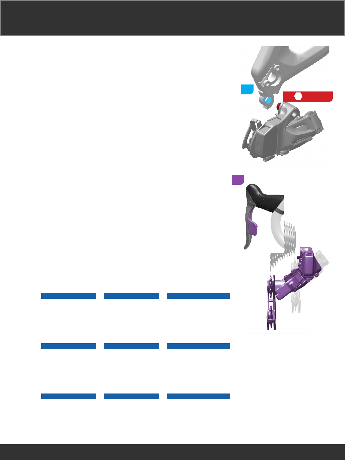
Rear Derailleur Installation Rear Derailleur Installation Rear Derailleur Installation
Rear Derailleur Installation Rear Derailleur Installation Rear Derailleur Installation
Rear Derailleur Installation Rear Derailleur Installation Rear Derailleur Installation
2
5
8-10 N·m
(70-88 in-lb)
1
3
Press and hold the left
shift paddle to shift the
rear derailleur until it is
fully extended.
Press and hold the left
shift paddle to shift the
rear derailleur until it is
fully extended.
Press and hold the left
shift paddle to shift the
rear derailleur until it is
fully extended.
Press and hold the left
shift paddle to shift the
rear derailleur until it is
fully extended.
Press and hold the left
shift paddle to shift the
rear derailleur until it is
fully extended.
Press and hold the left
shift paddle to shift the
rear derailleur until it is
fully extended.
Press and hold the left
shift paddle to shift the
rear derailleur until it is
fully extended.
Press and hold the left
shift paddle to shift the
rear derailleur until it is
fully extended.
Press and hold the left
shift paddle to shift the
rear derailleur until it is
fully extended.
NOTICE
Do not manually force
the derailleur to move
inboard or outboard.
Forcing the derailleur
to move will damage
the motor.
NOTICE
Do not manually force
the derailleur to move
inboard or outboard.
Forcing the derailleur
to move will damage
the motor.
NOTICE
Do not manually force the
derailleur to move inboard
or outboard. Forcing the
derailleur to move will
damage the motor.
NOTICE
Do not manually force
the derailleur to move
inboard or outboard.
Forcing the derailleur
to move will damage
the motor.
NOTICE
Do not manually force
the derailleur to move
inboard or outboard.
Forcing the derailleur
to move will damage
the motor.
NOTICE
Do not manually force the
derailleur to move inboard
or outboard. Forcing the
derailleur to move will
damage the motor.
17
Align the pulley wheel with the largest
cog by performing a micro-adjust.
Inboard: Press the left shifter function
button while actuating the shift paddle
to micro-adjust the rear derailleur
inboard 0.25 mm.
Outboard: Press the right shifter
function button while actuating the
shift paddle to micro-adjust the rear
derailleur outboard 0.25 mm. Continue
to hold and shift to perform multiple
micro-adjusts.
18
Mid Cage
26/28T
= 6 mm
6
2.5
=
=
Use your fingers to
adjust the low limit
screw so that it lightly
contacts the inner link of
the rear derailleur.
Use your fingers to
adjust the low limit
screw so that it lightly
contacts the inner link of
the rear derailleur.
Use your fingers to
adjust the low limit
screw so that it lightly
contacts the inner link of
the rear derailleur.
Use your fingers to
adjust the low limit
screw so that it lightly
contacts the inner link of
the rear derailleur.
Use your fingers to
adjust the low limit
screw so that it lightly
contacts the inner link of
the rear derailleur.
Use your fingers to
adjust the low limit
screw so that it lightly
contacts the inner link of
the rear derailleur.
Use your fingers to
adjust the low limit
screw so that it lightly
contacts the inner link of
the rear derailleur.
Use your fingers to
adjust the low limit
screw so that it lightly
contacts the inner link of
the rear derailleur.
Use your fingers to
adjust the low limit
screw so that it lightly
contacts the inner link of
the rear derailleur.
19
Press and hold the right
shift paddle to shift the
rear derailleur until it is
fully compacted.
Press and hold the right
shift paddle to shift the
rear derailleur until it is
fully compacted.
Press and hold the right
shift paddle to shift the
rear derailleur until it is
fully compacted.
Press and hold the right
shift paddle to shift the
rear derailleur until it is
fully compacted.
Press and hold the right
shift paddle to shift the
rear derailleur until it is
fully compacted.
Press and hold the right
shift paddle to shift the
rear derailleur until it is
fully compacted.
Press and hold the right
shift paddle to shift the
rear derailleur until it is
fully compacted.
Press and hold the right
shift paddle to shift the
rear derailleur until it is
fully compacted.
Press and hold the right
shift paddle to shift the
rear derailleur until it is
fully compacted.
NOTICE
Do not manually force
the derailleur to move
inboard or outboard.
Forcing the derailleur
to move will damage
the motor.
NOTICE
Do not manually force
the derailleur to move
inboard or outboard.
Forcing the derailleur
to move will damage
the motor.
NOTICE
Do not manually force the
derailleur to move inboard
or outboard. Forcing the
derailleur to move will
damage the motor.
NOTICE
Do not manually force
the derailleur to move
inboard or outboard.
Forcing the derailleur
to move will damage
the motor.
NOTICE
Do not manually force
the derailleur to move
inboard or outboard.
Forcing the derailleur
to move will damage
the motor.
NOTICE
Do not manually force the
derailleur to move inboard
or outboard. Forcing the
derailleur to move will
damage the motor.
Use a 2.5 mm hex
wrench to adjust the
high limit screw until it
lightly touches the inner
link of the rear derailleur.
Use a 2.5 mm hex
wrench to adjust the
high limit screw until it
lightly touches the inner
link of the rear derailleur.
Use a 2.5 mm hex
wrench to adjust the
high limit screw until it
lightly touches the inner
link of the rear derailleur.
Use a 2.5 mm hex
wrench to adjust the
high limit screw until it
lightly touches the inner
link of the rear derailleur.
Use a 2.5 mm hex
wrench to adjust the
high limit screw until it
lightly touches the inner
link of the rear derailleur.
Use a 2.5 mm hex
wrench to adjust the
high limit screw until it
lightly touches the inner
link of the rear derailleur.
Use a 2.5 mm hex
wrench to adjust the
high limit screw until it
lightly touches the inner
link of the rear derailleur.
Use a 2.5 mm hex
wrench to adjust the
high limit screw until it
lightly touches the inner
link of the rear derailleur.
Use a 2.5 mm hex
wrench to adjust the
high limit screw until it
lightly touches the inner
link of the rear derailleur.
20
Chain Installation Chain Installation Chain Installation
Chain Installation Chain Installation Chain Installation
Chain Installation Chain Installation Chain Installation
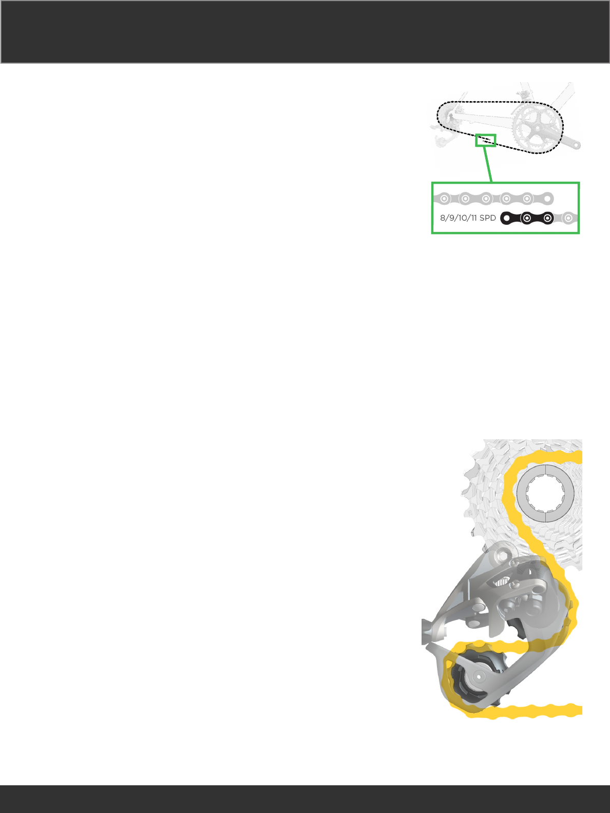
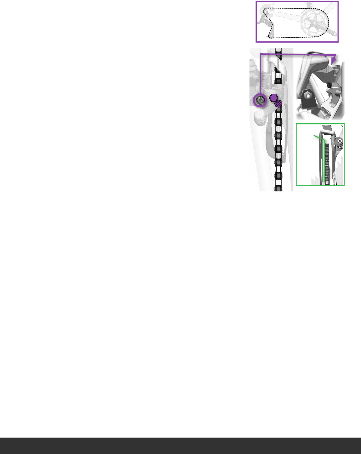
Wrap the chain around
the largest cog on the
rear derailleur and the
large chainring. From
where the chain meets,
add one inner and one
outer link. Use a chain
tool to remove the
excess chain.
Wrap the chain around
the largest cog on the
rear derailleur and the
large chainring. From
where the chain meets,
add one inner and one
outer link. Use a chain
tool to remove the
excess chain.
Wrap the chain around
the largest cog on the
rear derailleur and the
large chainring. From
where the chain meets,
add one inner and one
outer link. Use a chain
tool to remove the
excess chain.
Wrap the chain around
the largest cog on the
rear derailleur and the
large chainring. From
where the chain meets,
add one inner and one
outer link. Use a chain
tool to remove the
excess chain.
Wrap the chain around
the largest cog on the
rear derailleur and the
large chainring. From
where the chain meets,
add one inner and one
outer link. Use a chain
tool to remove the
excess chain.
Wrap the chain around
the largest cog on the
rear derailleur and the
large chainring. From
where the chain meets,
add one inner and one
outer link. Use a chain
tool to remove the
excess chain.
Wrap the chain around
the largest cog on the
rear derailleur and the
large chainring. From
where the chain meets,
add one inner and one
outer link. Use a chain
tool to remove the
excess chain.
Wrap the chain around
the largest cog on the
rear derailleur and the
large chainring. From
where the chain meets,
add one inner and one
outer link. Use a chain
tool to remove the
excess chain.
Wrap the chain around
the largest cog on the
rear derailleur and the
large chainring. From
where the chain meets,
add one inner and one
outer link. Use a chain
tool to remove the
excess chain.
Route the chain through
the rear derailleur.
Route the chain through
the rear derailleur.
Route the chain through
the rear derailleur.
Route the chain through
the rear derailleur.
Route the chain through
the rear derailleur.
Route the chain through
the rear derailleur.
Route the chain through
the rear derailleur.
Route the chain through
the rear derailleur.
Route the chain through
the rear derailleur.
21
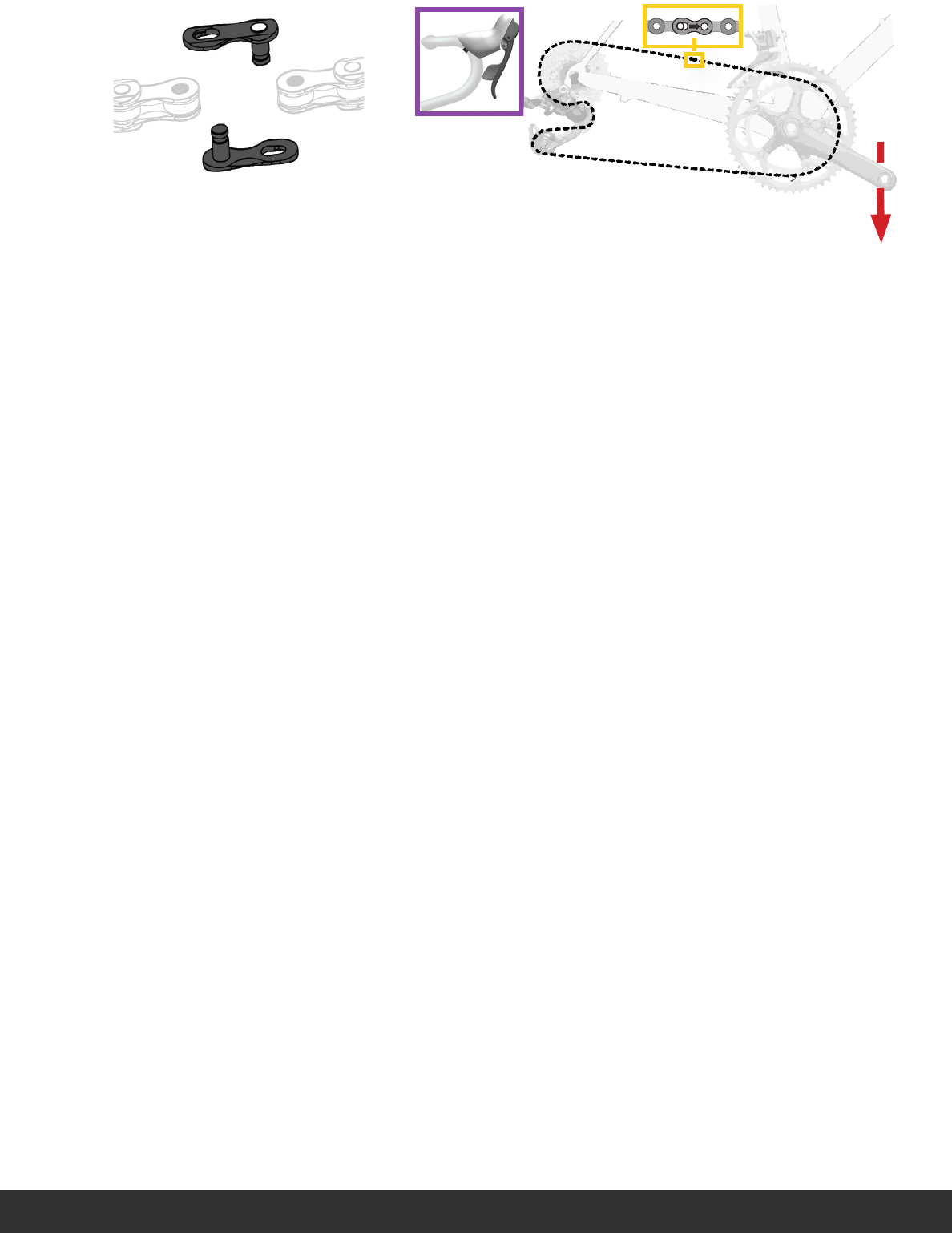
Install the
PowerLock.
Install the
PowerLock.
Install the
PowerLock.
Install the
PowerLock.
Install the
PowerLock.
Install the
PowerLock.
Install the
PowerLock.
Install the
PowerLock.
Install the
PowerLock.
Squeeze the brake
lever while pushing the
crankarm down to lock
the PowerLock into
place.
Squeeze the brake
lever while pushing the
crankarm down to lock
the PowerLock into
place.
Squeeze the brake
lever while pushing the
crankarm down to lock
the PowerLock into
place.
Squeeze the brake
lever while pushing the
crankarm down to lock
the PowerLock into
place.
Squeeze the brake
lever while pushing the
crankarm down to lock
the PowerLock into
place.
Squeeze the brake
lever while pushing the
crankarm down to lock
the PowerLock into
place.
Squeeze the brake
lever while pushing the
crankarm down to lock
the PowerLock into
place.
Squeeze the brake
lever while pushing the
crankarm down to lock
the PowerLock into
place.
Squeeze the brake
lever while pushing the
crankarm down to lock
the PowerLock into
place.
22
Front Derailleur Adjustment Front Derailleur Adjustment Front Derailleur Adjustment
Front Derailleur Adjustment Front Derailleur Adjustment Front Derailleur Adjustment
Front Derailleur Adjustment Front Derailleur Adjustment Front Derailleur Adjustment
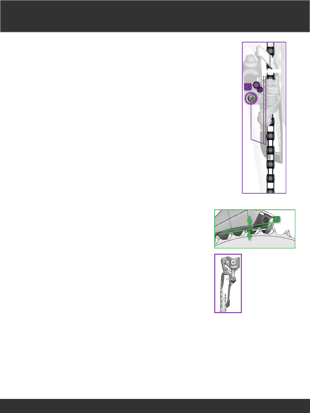
Use a 2.5 mm hex
wrench to adjust the low
limit screw so there is .5
mm between the chain
and the outside edge of
the rear derailleur.
Use a 2.5 mm hex
wrench to adjust the low
limit screw so there is .5
mm between the chain
and the outside edge of
the rear derailleur.
Use a 2.5 mm hex
wrench to adjust the low
limit screw so there is .5
mm between the chain
and the outside edge of
the rear derailleur.
Use a 2.5 mm hex
wrench to adjust the low
limit screw so there is .5
mm between the chain
and the outside edge of
the rear derailleur.
Use a 2.5 mm hex
wrench to adjust the low
limit screw so there is .5
mm between the chain
and the outside edge of
the rear derailleur.
Use a 2.5 mm hex
wrench to adjust the low
limit screw so there is .5
mm between the chain
and the outside edge of
the rear derailleur.
Use a 2.5 mm hex
wrench to adjust the low
limit screw so there is .5
mm between the chain
and the outside edge of
the rear derailleur.
Use a 2.5 mm hex
wrench to adjust the low
limit screw so there is .5
mm between the chain
and the outside edge of
the rear derailleur.
Use a 2.5 mm hex
wrench to adjust the low
limit screw so there is .5
mm between the chain
and the outside edge of
the rear derailleur.
Measure the gap
between the tallest teeth
of the large chainring
and bottom edge of the
outer cage plate. The
gap must be 1-2 mm.
If it is not, adjust the
height of the derailleur
(_ & _), then repeat steps
_, __, and __.
Measure the gap
between the tallest teeth
of the large chainring
and bottom edge of the
outer cage plate. The
gap must be 1-2 mm.
If it is not, adjust the
height of the derailleur
(_ & _), then repeat steps
_, __, and __.
Measure the gap
between the tallest teeth
of the large chainring
and bottom edge of the
outer cage plate. The
gap must be 1-2 mm.
If it is not, adjust the
height of the derailleur
(_ & _), then repeat steps
_, __, and __.
Measure the gap
between the tallest teeth
of the large chainring
and bottom edge of the
outer cage plate. The
gap must be 1-2 mm.
If it is not, adjust the
height of the derailleur
(_ & _), then repeat steps
_, __, and __.
Measure the gap
between the tallest teeth
of the large chainring
and bottom edge of the
outer cage plate. The
gap must be 1-2 mm.
If it is not, adjust the
height of the derailleur
(_ & _), then repeat steps
_, __, and __.
Measure the gap
between the tallest teeth
of the large chainring
and bottom edge of the
outer cage plate. The
gap must be 1-2 mm.
If it is not, adjust the
height of the derailleur
(_ & _), then repeat steps
_, __, and __.
Measure the gap
between the tallest teeth
of the large chainring
and bottom edge of the
outer cage plate. The
gap must be 1-2 mm.
If it is not, adjust the
height of the derailleur
(_ & _), then repeat steps
_, __, and __.
Measure the gap
between the tallest teeth
of the large chainring
and bottom edge of the
outer cage plate. The
gap must be 1-2 mm.
If it is not, adjust the
height of the derailleur
(_ & _), then repeat steps
_, __, and __.
Measure the gap
between the tallest teeth
of the large chainring
and bottom edge of the
outer cage plate. The
gap must be 1-2 mm.
If it is not, adjust the
height of the derailleur
(_ & _), then repeat steps
_, __, and __.
12
2.5
L
0.5 mm
13
1-2 mm
23
With the chain as
illustrated, use a 2.5 mm
hex to turn the high limit
screw until there is 1 mm
of clearance between
the inside of the outer
derailleur cage plate and
the chain.
With the chain as
illustrated, use a 2.5 mm
hex to turn the high limit
screw until there is 1 mm
of clearance between
the inside of the outer
derailleur cage plate and
the chain.
With the chain as
illustrated, use a 2.5 mm
hex to turn the high limit
screw until there is 1 mm
of clearance between
the inside of the outer
derailleur cage plate and
the chain.
With the chain as
illustrated, use a 2.5 mm
hex to turn the high limit
screw until there is 1 mm
of clearance between
the inside of the outer
derailleur cage plate and
the chain.
With the chain as
illustrated, use a 2.5 mm
hex to turn the high limit
screw until there is 1 mm
of clearance between
the inside of the outer
derailleur cage plate and
the chain.
With the chain as
illustrated, use a 2.5 mm
hex to turn the high limit
screw until there is 1 mm
of clearance between
the inside of the outer
derailleur cage plate and
the chain.
With the chain as
illustrated, use a 2.5 mm
hex to turn the high limit
screw until there is 1 mm
of clearance between
the inside of the outer
derailleur cage plate and
the chain.
With the chain as
illustrated, use a 2.5 mm
hex to turn the high limit
screw until there is 1 mm
of clearance between
the inside of the outer
derailleur cage plate and
the chain.
With the chain as
illustrated, use a 2.5 mm
hex to turn the high limit
screw until there is 1 mm
of clearance between
the inside of the outer
derailleur cage plate and
the chain.
H
1 mm
B
C
D
2.5

24
Fine Tuning Fine Tuning Fine Tuning
Fine Tuning Fine Tuning Fine Tuning
Fine Tuning Fine Tuning Fine Tuning
Fine-tune the rear derailleur shifting
performance by using micro-
adjustments.
Inboard: Press the left shifter function
button while actuating the shift paddle
to micro-adjust the rear derailleur
inboard 0.25 mm.
Outboard: Press the right shifter
function button while actuating the
shift paddle to micro-adjust the rear
derailleur outboard 0.25 mm.

25
Maintenance Maintenance Maintenance
Maintenance Maintenance Maintenance
Maintenance Maintenance Maintenance
Periodic cleaning is recommended.
Use a damp cloth to wipe the
components until clean.
Periodic cleaning is recommended.
Use a damp cloth to wipe the
components until clean.
Periodic cleaning is recommended.
Use a damp cloth to wipe the
components until clean.
Periodic cleaning is recommended.
Use a damp cloth to wipe the
components until clean.
Periodic cleaning is recommended.
Use a damp cloth to wipe the
components until clean.
Periodic cleaning is recommended.
Use a damp cloth to wipe the
components until clean.
Periodic cleaning is recommended.
Use a damp cloth to wipe the
components until clean.
Periodic cleaning is recommended.
Use a damp cloth to wipe the
components until clean.
Periodic cleaning is recommended.
Use a damp cloth to wipe the
components until clean.

26
Firmware Update Dongle Firmware Update Dongle Firmware Update Dongle
Firmware Update Dongle Firmware Update Dongle Firmware Update Dongle
Firmware Update Dongle Firmware Update Dongle Firmware Update Dongle
Use the Firmware Update Dongle to
communicate the firmware update
between your components and the
computer.
Install the Firmware Update Dongle
into a USB drive on your computer. The
dongle will automatically install the
necessary drivers.
Go to www.sram.com/registration to
download the firmware update, then
follow the prompts to update the
component's firmware.
For software updates related to your
products, please register online at
www.sram.com/registration.
Use the Firmware Update Dongle to
communicate the firmware update
between your components and the
computer.
Install the Firmware Update Dongle
into a USB drive on your computer.
The dongle will automatically install
the necessary drivers.
Go to www.sram.com/registration to
download the firmware update, then
follow the prompts to update the
component's firmware.
For software updates related to your
products, please register online at
www.sram.com/registration.
Use the Firmware Update Dongle to
communicate the firmware update
between your components and the
computer.
Install the Firmware Update Dongle
into a USB drive on your computer. The
dongle will automatically install the
necessary drivers.
Go to www.sram.com/registration to
download the firmware update, then
follow the prompts to update the
component's firmware.
For software updates related to your
products, please register online at
www.sram.com/registration.
Use the Firmware Update Dongle to
communicate the firmware update
between your components and the
computer.
Install the Firmware Update Dongle
into a USB drive on your computer.
The dongle will automatically install
the necessary drivers.
Go to www.sram.com/registration to
download the firmware update, then
follow the prompts to update the
component's firmware.
For software updates related to your
products, please register online at
www.sram.com/registration.

27
WARNING
Do not use or clean the components without
connector wires or dummy plugs installed.
Moisture will damage the components.
Use and store the device within the
temperature ranges specified in the
Declaration of Conformity, and Hazards and
Warnings document at
www.sram.com.
Avoid chemical cleaners and solvents that
can damage plastic components.
Do not submerge the components in liquid
of any kind.
Do not clean the components with a power
washer.
28
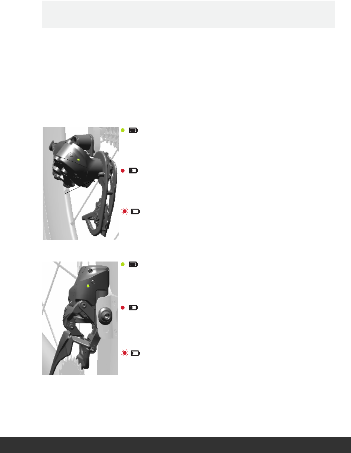
90-22 hours 90-22 hours 90-22 hours
90-22 hours 90-22 hours 90-22 hours
90-22 hours 90-22 hours 90-22 hours
22-9 hours 22-9 hours 22-9 hours
22-9 hours 22-9 hours 22-9 hours
22-9 hours 22-9 hours 22-9 hours
8-1 hours 8-1 hours 8-1 hours
8-1 hours 8-1 hours 8-1 hours
8-1 hours 8-1 hours 8-1 hours
60-15 hours 60-15 hours 60-15 hours
60-15 hours 60-15 hours 60-15 hours
60-15 hours 60-15 hours 60-15 hours
15-6 hours 15-6 hours 15-6 hours
15-6 hours 15-6 hours 15-6 hours
15-6 hours 15-6 hours 15-6 hours
5-1 hours 5-1 hours 5-1 hours
5-1 hours 5-1 hours 5-1 hours
5-1 hours 5-1 hours 5-1 hours
The LED color indicates the battery life
remaining, and lights up when a shift is
performed.
The LED color indicates the battery life
remaining, and lights up when a shift is
performed.
The LED color indicates the battery life
remaining, and lights up when a shift is
performed.
The LED color indicates the battery life
remaining, and lights up when a shift is
performed.
The LED color indicates the battery life
remaining, and lights up when a shift is
performed.
The LED color indicates the battery life
remaining, and lights up when a shift is
performed.
The LED color indicates the battery life
remaining, and lights up when a shift is
performed.
The LED color indicates the battery life
remaining, and lights up when a shift is
performed.
The LED color indicates the battery life
remaining, and lights up when a shift is
performed.
Battery Status Lights Battery Status Lights Battery Status Lights
Battery Status Lights Battery Status Lights Battery Status Lights
Battery Status Lights Battery Status Lights Battery Status Lights

29
Shifter Battery Replacement Shifter Battery Replacement Shifter Battery Replacement
Shifter Battery Replacement Shifter Battery Replacement Shifter Battery Replacement
Shifter Battery Replacement Shifter Battery Replacement Shifter Battery Replacement
WARNING
Do not use sharp objects to remove
batteries.
Keep out of reach of children.
Do not put the battery in your mouth.
If ingested, seek medical attention
immediately.
Do not disassemble, damage, or puncture
the battery.
Consult the battery manufacturer for safe
handling instructions.
WARNING
Do not use sharp objects to remove
batteries.
Keep out of reach of children.
Do not put the battery in mouth. If ingested,
seek medical attention immediately.
Do not disassemble, damage, or puncture
the battery.
Consult the battery manufacturer for safe
handling instructions.
WARNING
Do not use sharp objects to remove
batteries.
Keep out of reach of children.
Do not put the battery in mouth. If ingested,
seek medical attention immediately.
Do not disassemble, damage, or puncture
the battery.
Consult the battery manufacturer for safe
handling instructions.
WARNING
Do not use sharp objects to remove
batteries.
Keep out of reach of children.
Do not put the battery in mouth. If ingested,
seek medical attention immediately.
Do not disassemble, damage, or puncture
the battery.
Consult the battery manufacturer for safe
handling instructions.
WARNING
Do not use sharp objects to remove
batteries.
Keep out of reach of children.
Do not put the battery in mouth. If ingested,
seek medical attention immediately.
Do not disassemble, damage, or puncture
the battery.
Consult the battery manufacturer for safe
handling instructions.
WARNING
Do not use sharp objects to remove
batteries.
Keep out of reach of children.
Do not put the battery in mouth. If ingested,
seek medical attention immediately.
Do not disassemble, damage, or puncture
the battery.
Consult the battery manufacturer for safe
handling instructions.
WARNING
Do not use sharp objects to remove
batteries.
Keep out of reach of children.
Do not put the battery in mouth. If ingested,
seek medical attention immediately.
Do not disassemble, damage, or puncture
the battery.
Consult the battery manufacturer for safe
handling instructions.
WARNING
Do not use sharp objects to remove
batteries.
Keep out of reach of children.
Do not put the battery in mouth. If ingested,
seek medical attention immediately.
Do not disassemble, damage, or puncture
the battery.
Consult the battery manufacturer for safe
handling instructions.
WARNING
Do not use sharp objects to remove
batteries.
Keep out of reach of children.
Do not put the battery in mouth. If ingested,
seek medical attention immediately.
Do not disassemble, damage, or puncture
the battery.
Consult the battery manufacturer for safe
handling instructions.

30
For consumers in the United States
and Canada, SRAM has partnered
with the Rechargeable Battery
Recycling Corporation. Please call
1-800-8-BATTERY or visit
www.rbrc.org for additional
information.
Replace the battery with an authentic
SRAM replacement battery only.
Used batteries must be recycled in
accordance with local and federal
government regulations.
WARNING
Do not throw batteries in a fire.
Recycling Recycling Recycling
Recycling Recycling Recycling
Recycling Recycling Recycling

31
Compliance Compliance Compliance
Compliance Compliance Compliance
Compliance Compliance Compliance
SRAM LLC certifies that this product and its packaging are in compliance with:
R&TTE Directive, the Radio and Telecommunication Terminal Equipment Directive 1999/5/EC
WEEE Directive, the Waste Electrical and Electronic Equipment Directive 2012/19/EU
RoHS Directive, the restriction of the use of certain hazardous substances in electrical and electronic equipment 2002/95/
EC
REACh Directive, the Regulation on Registration, Evaluation, Authorization and Restriction of Chemical Directive 1907/2006/
EC
Batteries and Accumulators and Waste Batteries and Accumulators Directive 2006/66/EU
This device complies with Part 15 of the FCC Rules. Operation is subject to the following two conditions: (1) this device may
not cause harmful interference, and (2) this device must accept any interference received, including interference that may
cause undesired operation.
Note: This equipment has been tested and found to comply with the limits for a Class B digital device, pursuant to part 15
of the FCC Rules. These limits are designed to provide reasonable protection against harmful interference in a residential
installation. This equipment generates, uses and can radiate radio frequency energy and, if not installed and used in
accordance with the instructions, may cause harmful interference to radio communications. However, there is no guarantee
that interference will not occur in a particular installation. If this equipment does cause harmful interference to radio or
television reception, which can be determined by turning the equipment off and on, the user is encouraged to try to correct
the interference by one or more of the following measures:
• Reorient or relocate the receiving antenna.
• Increase the separation between the equipment and receiver.
• Connect the equipment into an outlet on a circuit different from that to which the receiver is connected.
• Consult the dealer or an experienced radio/TV technician for help.
This device complies with Industry Canada’s license-exempt RSS standard(s). Operation is subject to the following
two conditions: (1) this device may not cause interference, and (2) this device must accept any interference, including
interference that may cause undesired operation of the device.
The term “IC:” before the radio certification number only signifies that Industry Canada technical specifications were met.
Canadian Department of Communications Compliance Statement:
Firmware Update Dongle - DOC: CAN ICES-3(B)/NMB-3(B) C
Le présent appareil est conforme aux CNR d'Industrie Canada applicables aux appareils radio exempts de licence.
L'exploitation est autorisée aux deux conditions suivantes : (1) l'appareil ne doit pas produire de brouillage, et (2) l'utilisateur
de l'appareil doit accepter tout brouillage radioélectrique subi, même si le brouillage est susceptible d'en compromettre le
fonctionnement.
Warning: Any changes or modifications not expressively approved by SRAM could void the user's authority to operate this
equipment.
This product is ANT+ certified and complies with the bicycle power ANT+ Device Profile. For a complete listing of ANT+
Certified Products and their specific interoperability, please visit www.thisisant.com.
SRAM LLC WORLD HEADQUARTERS
1000 W. Fulton Market, 4th Floor
Chicago, Illinois 60607
USA
Left Shifter
Model#:00001
FCC ID: C9O-LSBED
IC: 10161A-LSBED
Right Shifter
Model#:00101
FCC ID: C9O-RSBED
IC: 10161A-RSBED
BlipBox
Model#:00201
FCC ID: C9O-BOXED
IC: 10161A-BOXED
Firmware Update Dongle
Model#:12701
FCC ID: C9O-LINKED
IC: 10161A-LINKED
Front Derailleur
Model#:12801
FCC ID: C9O-FDED
IC: 10161A-FDED
Rear Derailleur
Model#:12901
FCC ID: C9O-RDED
IC: 10161A-RDED

32
Specifications Specifications Specifications
Specifications Specifications Specifications
Specifications Specifications Specifications
Rechargeable Lithium-ion Polymer Battery Model: 25401
Cell Type 300mAh/3.7V
Pack Configuration 2S1P
Nominal Voltage 7.4 DC
EOD Voltage 6.0V DC
Nominal Capacity 300mAh
Minimum Capacity 290mAh
(at 0.2C discharge rate 3.0v cut off after standard charge)
Average Working Voltage 7.4V at 0.2C rate
Fast Charge Constant current 1.0C
Constant Voltage 8.4V
Operating Temperature Range
Standard Charge 32° to 114°F / 0° to 45°C
Discharge -4° to 140°F / -20° to 60°C
Weight of Battery Approx 6.5 g
Cell Dimension
Length Max.30.0mm
Width Max. 19.0mm
Thickness Max. Thickness: Max. 6.0mm
Storage at 50% SOC and specified temp, recoverable capacities in % vs. time.
-20° to 25°C (12 months, 85% ) 25° to 45°C (3 months, 80% )
60° to 70°C (1 hour, 85% )) 70° to 85°C (1 hour, 80% )
Battery Charger Model: 25301
The charger is designed to meet EMI safety standards for use in information technology equipment.
Rated Input Voltage 5V DC
Maximum Rated Output Voltage 8.4V
Operating Temperature Range 32°F to 104°F / 0°C to 40°C
Non-operating Temperature Range 50° to 140°F / 10°C to 60°
Relative Humidity for Operating and Non-operating 10% to 80%
Replacable Lithium Coin Cell Battery CR2032
Consult the battery manufacturer's instructions for technical information.

33
“We will revolutionize the relationship that our users have with SRAM products,
cultivating a bond between the rider and bicycle. Our technical communication
will be delivered in innovative and exciting ways, with deliberation and accuracy
that inspires loyalty and trust across the globe.”
-SRAM TechCom Vision Statement
ASIAN HEADQUARTERS
SRAM Taiwan
No. 1598-8 Chung Shan Road
Shen Kang Hsiang, Taichung City
Taiwan R.O.C.
WORLD HEADQUARTERS
SRAM LLC
1000 W. Fulton Market, 4th Floor
Chicago, Illinois 60607
USA
EUROPEAN HEADQUARTERS
SRAM Europe
Paasbosweg 14-16
3862ZS Nijkerk
The Netherlands
www.sram.com