SRAM MERC1 2.4 GHz BICYCLE POWER METER User Manual Users Guide
SRAM LLC. 2.4 GHz BICYCLE POWER METER Users Guide
SRAM >
Users Guide

95.6118.000.000 Rev A Copyright ©SRAM LLC, 2012

3
2
This publication includes trademarks and registered trademarks of SRAM LLC designated by the symbols ™
and ®, respectively.
Product names used in this publication may be trademarks or registered trademarks of others.
SRAM LLC Warranty
Extent of Limited Warranty
SRAM warrants its products to be free from defects in materials or workmanship for a period of two years
after original purchase. This warranty only applies to the original owner and is not transferable. Claims under
this warranty must be made through the retailer where the bicycle or the SRAM component was purchased.
Original proof of purchase is required.
Local law
This warranty statement gives the customer specific legal rights. The customer may also have other rights
which vary from state to state (USA), from province to province (Canada), and from country to country
elsewhere in the world.
To the extent that this warranty statement is inconsistent with the local law, this warranty shall be deemed
modified to be consistent with such law, under such local law, certain disclaimers and limitations of this
warranty statement may apply to the customer. For example, some states in the United States of America, as
well as some governments outside of the United States (including provinces in Canada) may:
a. Preclude the disclaimers and limitations of this warranty statement from limiting the statutory rights of the
consumer (e.g. United Kingdom).
b. Otherwise restrict the ability of a manufacturer to enforce such disclaimers or limitations.
Limitations of Liability
To the extent allowed by local law, except for the obligations specifically set forth in this warranty statement, in
no event shall SRAM or its third party supplies be liable for direct, indirect, special, incidental, or consequential
damages.
Limitations of Warranty
This warranty does not apply to products that have been incorrectly installed and/or adjusted according to the
respective SRAM technical installation manual. The SRAM installation manuals can be found online at
sram.com, rockshox.com, avidbike.com, truvativ.com, zipp.com, or quarq.com.
This warranty does not apply to damage to the product caused by a crash, impact, abuse of the product, non-
compliance with manufacturers specifications of usage or any other circumstances in which the product has
been subjected to forces or loads beyond its design.
This warranty does not apply when the product has been modified.
This warranty does not apply when the serial number or production code has been deliberately altered,
defaced or removed.
This warranty does not apply to normal wear and tear. Wear and tear parts are subject to damage as a result
of normal use, failure to service according to SRAM recommendations and/or riding or installation in conditions
or applications other than recommended.
Statement of Compliance for FCC and Industry Canada:
Quarq Technology / SRAM LLC.
Model#: 0808
FCC ID: C9O-MERC1
IC: 1016A-MERC1
This equipment has been tested and found to comply with the limits for a Class B digital device, pursuant to
Part 15 of the FCC Rules. These limits are designed to provide reasonable protection against harmful interfer-
ence in a residential installation. This equipment generates uses and can radiate radio frequency energy and,
if not installed and used in accordance with the instructions, may cause harmful interference to radio commu-
nications. However, there is no guarantee that interference will not occur in a particular installation.
Operation is subject to the following two conditions:
1 This device may not cause harmful interference, and
2 this device must accept any interference received, including interference that may cause undesired
operation.
This product meets the applicable Industry Canada technical specications.
Le présent matériel est conforme aux specications techniques applicables d’Industrie Canada.
The term “IC:” before the radio certication number only signies that Industry Canada technical specications
were met.
Warning: Any changes or modications not expressively approved by SRAM could void the user’s authority to
operate this equipment.
Statement of RoHS Compliance:
Quarq Technology / SRAM LLC. certies that this product and its packaging are in compliance with European
Union Directive 2002/95/EC on the Restriction of the Use of Certain Hazardous Substances in Electrical and
Electronics Equipment, commonly known as RoHS.
ANT+(TM) Product Certication
This product is ANT+ certied and complies with the bicycle power ANT+ Device Prole. For a complete listing
of ANT+ Certied Products and their specic interoperability, please visit www.thisisant.com.

5
4
Table of ConTenTs
Wear and tear parts are identified as:
This warranty shall not cover damages caused by the use of parts of different manufacturers.
This warranty shall not cover damages caused by the use of parts that are not compatible, suitable and/or
authorised by SRAM for use with SRAM components.
This warranty shall not cover damages resulting from commercial (rental) use.
• Dust seals
• Bushings
• Air sealing o-rings
• Glide rings
• Rubber moving parts
• Foam rings
• Rear shock mounting hardware and
main seals
• Upper tubes (stanchions)
• Stripped threads/bolts (aluminium,
titanium, magnesium or steel)
• Brake sleeves
• Brake pads
• Chains
• Sprockets
• Cassettes
• Shifter and brake cables
(inner and outer)
• Handlebar grips
• Shifter grips
• Jockey wheels
• Disc brake rotors
• Wheel braking surfaces
• Bottomout pads
• Bearings
• Bearing races
• Pawls
• Transmission gears
• Spokes
• Free hubs
• Aero bar pads
• Corrosion
• Tools
• Batteries
TABLE OF CONTENTS
POWER METER ANATOMY ................................................................................. 6
INSTALLATION ...................................................................................................... 7
MAGNET INSTALL ATION ..............................................................................................................7
BB CUP MOUNT INSTALLATION .............................................................................................. 8
CABLE GUIDE MOUNT INSTALLATION ................................................................................. 9
ADHESIVE PUTTY INSTALLATION .........................................................................................10
CRANK INSTALLATION ...................................................................................... 11
SET UP ................................................................................................................... 11
LED FUNCTIONALITY ...................................................................................................................11
PAIRING .............................................................................................................................................. 12
ZEROING ............................................................................................................................................ 12
CHAINRING INSTALLATION ..............................................................................14
MAINTENANCE AND CARE ................................................................................ 15
BAT TERY INFORMATION ............................................................................................................15
BATTERY CARE ............................................................................................................................... 15
CLEANING .........................................................................................................................................15
TROUBLESHOOTING ...........................................................................................16
7
6
INSTALLATION
Power meter AnAtomy
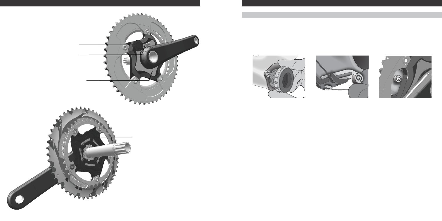
POWER METER ANATOMY
Cadence Sensor Ring
Battery Compartment
Crankarm Spider Serial Number
LED
INSTALLATION
Magnet InstallatIon
The included magnet must be installed for the power meter to function. There are three ways to install the
magnet: BB Cup Mount, Cable Guide Mount, and Adhesive Putty (only one type of mount can be use at a
time). When properly installed, the magnet should be in line with the cadence sensors and within 2-8 mm
of the sensors. If necessary, magnets may be stacked to achieve the proper distance to the sensor. Do
not allow the magnet to contact the power meter.
It is easier to install the magnet when the cranks are not installed on the frame.
BB Cup Mount Cable Guide Mount Adhesive Putty
9
8
Cable Guide Mount installation
BB Cup Mount InstallatIon
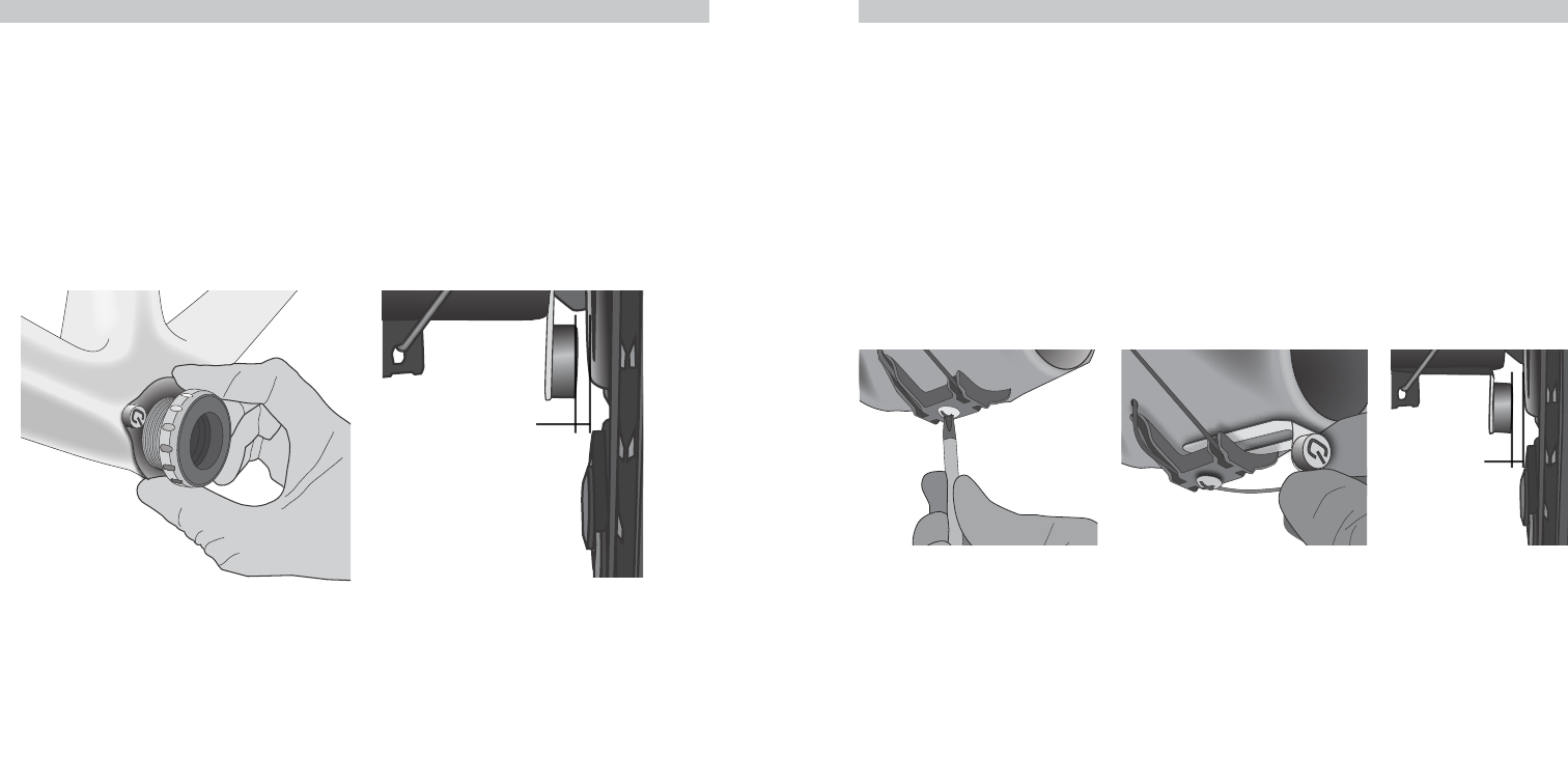
BB Cup Mount InstallatIon
The BB Cup Mount is only compatible with threaded bottom brackets. It does not work with frames that
have bearings pressed into the bottom bracket (BB30, PF30, etc.). Frames using threaded bottom bracket
adapters (ie. SRAM GXP30 BB Adapter) may use the BB Cup Mount if the mount is installed onto the
threaded drive side bottom bracket cup.
1. If necessary, remove the existing cranks and bottom bracket.
2. Slide the BB Cup Mount over the threads of the drive side bearing cup with the magnet facing away
from the frame.
3. Hold the magnet at the 9 o’clock position while the bottom bracket is tightened to the manufacturer’s
recommended torque.
4. Conrm the magnet is within 2-8 mm (1/16”-3/8”) of the sensor.
2-8 mm
(1/16”-3/8”)
CaBle guIde Mount InstallatIon
The Cable Guide Mount should only be used when the cable guide is fastened with a screw. If the cable
guide is fastened with a rivet, use the Bottom Bracket Cup Mount or Adhesive Putty instead.
Installation Notes: Do not allow the magnet to contact the power meter. When properly installed, the
magnet should be in line with the cadence sensors and within 2-8 mm (1/16”-3/8”) of the sensors.
1. Remove the existing cranks.
2. Loosen the cable guide screw. It may be helpful to shift the front derailleur to the small chainring
position, and the rear derailleur to the smallest cog. This will reduce the cable tension, and make it
easier to slide the cable guide mount under the cable guide.
3. Slide the mount under the cable guide.
4. Reinstall the cranks.
5. Tighten the cable guide screw.
6. Conrm the magnet is within 2-8 mm (1/16”-3/8”) of the sensor.
2-8 mm
(1/16”-3/8”)
11
10
Crank InstallatIon
Adhesive Putty instAllAtion
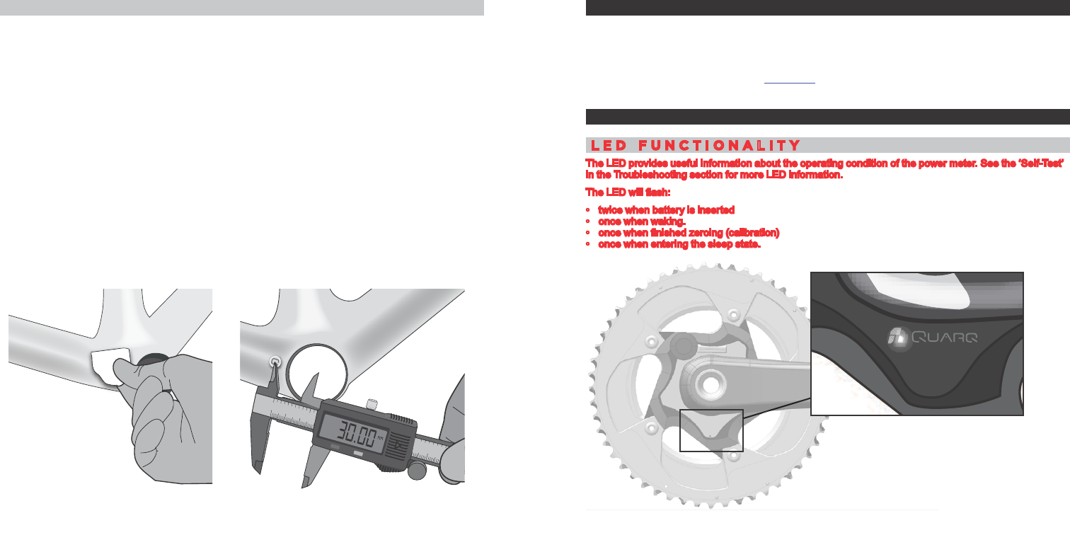
adhesIve putty InstallatIon
The included adhesive putty will permanently attach the magnet to your frame. Other non-permanent
attachment options include: hot glue, some epoxies, electrical tape, or similar adhesives.
Installation Notes: Do not allow the magnet to contact the power meter. When properly installed, the
magnet should be in line with the cadence sensors and within 2-8 mm (1/16”-3/8”) of the sensors.
Depending on your frame, you may need to stack 2-3 magnets to achieve this distance.
1. Remove the existing cranks.
2. Clean the frame with the included alcohol pad prior to attaching the magnet.
3. Knead both colors of adhesive putty with your ngers until you have one consistent color.
4. Place a 6 mm (1/4”) diameter ball of putty on the back of the magnet, and then press the magnet onto
the frame. The center of the magnet should be positioned between 30 mm and 38 mm (1 1/8”-1 1/2”)
from the center of the bottom bracket.
5. Use a toothpick to carefully remove any excess putty before it dries. The putty will set up in about 10
minutes, and will cure in 1 hour.
6. Reinstall the cranks.
7. Conrm the magnet is within 2-8 mm (1/16”-3/8”) of the sensor.
2
1
10
020 30 40
34578
692
134
130
140
89
2
1
34
5
mm/inch
OFF ON ZERO
100 120
2
13457
6
CRANK INSTALLATION
Install the crankset and bottom bracket assembly onto your bike according to the manufacturer’s
instructions.
Once the crankset has been installed, the power meter must not contact the frame or any other
components. Please contact Quarq customer service with any frame compatibility questions. An updated
list of compatible frames is available at Quarq.com.
SET UP
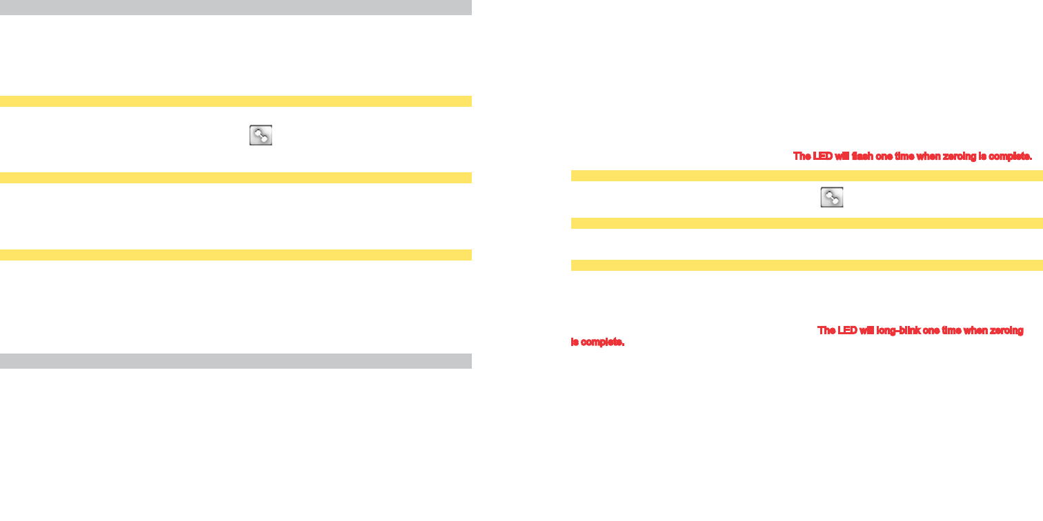
led FunCtIonalIty
The LED provides useful information about the operating condition of the power meter. See the ‘Self-Test’
in the Troubleshooting section for more LED information.
The LED will ash:
• twice when battery is inserted
• once when waking.
• once when nished zeroing (calibration)
• once when entering the sleep state.
13
12
Zeroing
Pairing
paIrIng
Before pairing your power meter to a computer, make sure you are at least 10 meters (30 feet) from any
other ANT+™ device. This will keep you from accidentally pairing to another person’s ANT+ device.
To pair the Quarq with an ANT+ computer, rst spin the crank backwards 2-3 times to wake the power meter
and begin broadcasting ANT+ messages. The power meter will shut off after about 10 minutes of inactivity.
Follow the pairing instructions specic to your ANT+ computer.
garMIn® edge 800
To pair the power meter:
Click the Power button → tap the Dumbbell icon → Rescan
“Power Meter Detected” will ash up on your screen when the units are paired.
garMIn edge 500
To pair the power meter:
Menu → Settings → Bike Settings → Bike 1 → ANT+Power → Rescan
“Power Meter Detected” will ash up on your screen when the units are paired.
garMIn Forerunner 310Xt WatCh
Your watch must be in bike mode in order to pair and zero your power meter (press and hold the Mode
button).
To pair the power meter:
Mode → Bike Settings → Bike 1 → Ant+Power → Restart Scan
“Power Meter Detected” will appear on your screen when the units are paired.
ZeroIng
The power meter must be zeroed to compensate for environmental changes. The power meter can be
zeroed two ways: Auto Zero and Manual Zero.
When to perform the Zero procedure
For best results, you should perform the Manual Zero procedure before you start each ride. The Auto
Zero procedure can be performed instead of a Manual Zero or if your computer cannot send a “Calibrate”
command; if the temperature changes greatly during your ride; or if you feel that you are getting inaccurate
data.
Manual Zero
We recommend that the Manual Zero procedure be performed with the rider off of the bike.
The power meter may be zeroed manually by sending the “Calibrate” command from an ANT+™
compatible bike computer. The power meter will return the Zero Offset value (or “Current Calibration” on
some computers) to the computer; however, not all ANT+ computers will display the value. The Zero Offset
is typically between +/- 500. Some units will always have a Zero Offset value outside of this range without
any impact on performance. What is more important is that the pre- and post-ride Zero Offset values are
within 50 points of each other. If the pre- and post-ride Zero Offset values frequently vary by more than 50,
or if day-to-day values vary widely, please call Quarq customer service.
When performing the Manual Zero procedure, put the drive side crank arm in the 6 o’clock position,
keeping the cranks stationary with no force on the pedals. Follow the pairing instructions specic to your
ANT+ computer to send the “Calibrate” command. The LED will ash one time when zeroing is complete.
garMIn® edge 800
Click the Power button → tap the Dumbbell icon → Calibrate
garMIn edge 500
Menu → Settings → Bike Settings → Bike 1 → ANT+Power → Calibrate
garMIn Forerunner 310Xt WatCh
Mode → Bike Settings → Bike 1 → Ant+Power → Calibrate
Auto Zero
Spin the crank backwards for 4-5 complete revolutions. The LED will long-blink one time when zeroing
is complete. The computer will not display the Zero Offset value. The Auto Zero procedure may be
performed while coasting with the rider on the bike, stopped using one or both feet, or by hand with the
rider off of the bike.
15
14
MAINTENANCE AND CARE
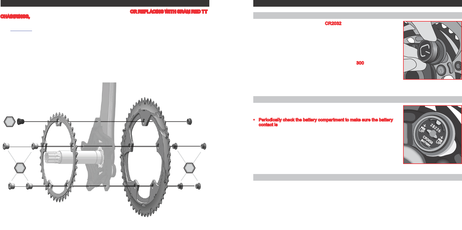
CHAINRING INstAllAtIoN
CHAINRING INSTALLATION
If you are replacing worn rings with a new pair of the same model, OR REPLACING WITH SRAM RED TT
CHAINRINGS, re-calibration is not required. If you are replacing your chainrings with a different model or
size, re-calibration is strongly recommended.
Visit Quarq.com for chainring compatibility tables, and calibration information. Your daily offset values will
be different than those you have previously noted.
When installing chainrings you must align the chainring tabs so they are in line with the crankarm.
Tighten the chainring bolts according to the manufacturer’s instruction.
MAINTENANCE AND CARE
Battery InForMatIon
• The power meter is powered by a CR2032 coin cell battery.
• The battery can be replaced without any special tools. To replace the
battery, unthread the lid counter-clockwise. Do not use any tools to pry
it open. The battery should be installed with the “+” facing out. Re-install
and hand tighten the battery cover after the battery is replaced.
• The power meter automatically switches on when the crankarms are
rotated, and shuts off after about 10 minutes of inactivity. Under normal
operating conditions the battery will last for about 300 hours of riding.
• The power meter will send a warning when the battery is low. However,
not all ANT+™ computers will display the message.
• The power meter retains its sensor ID throughout battery changes and
will remain properly paired with your computer.
Battery Care
• The battery must be installed correctly (“+” out) and have sufcient
charge.
• Periodically check the battery compartment to make sure the battery
contact is free of corrosion and moisture.
CleanIng
The power meter is very durable; however, periodic cleaning is recommended. Use a rag to wipe debris
from the power meter, crankarms, magnet, and chainrings. Brush the power meter, crankarms, magnet,
and chainrings with clean or soapy water, then rinse with clean water and let air dry. Do not use harsh
chemicals and do not use a high-pressure washer.
6
5 6
17
16
TROUBLESHOOTING
TROUBLESHOOTING
TROUBLESHOOTING
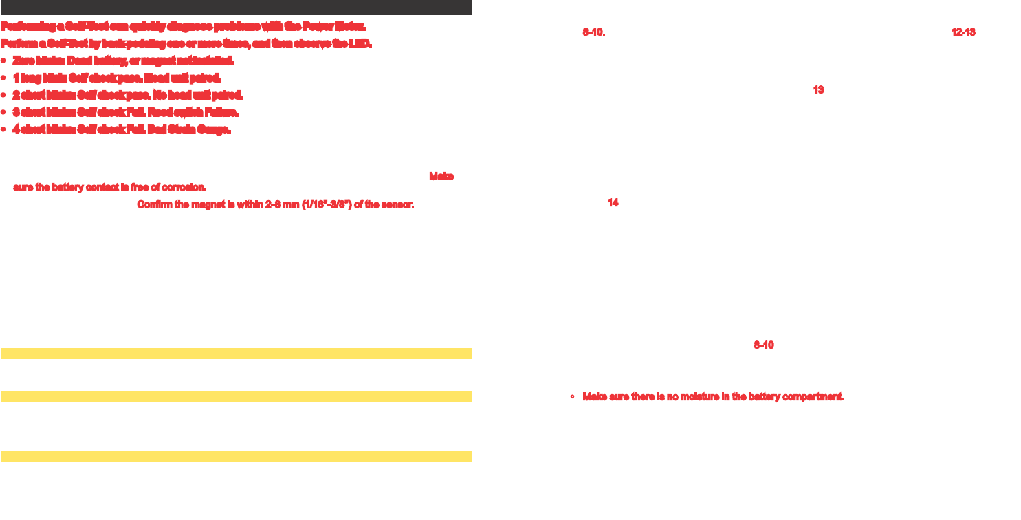
Performing a Self-Test can quickly diagnose problems with the Power Meter.
Perform a Self-Test by back-pedaling one or more times, and then observe the LED.
• Zero blinks: Dead battery, or magnet not installed.
• 1 long blink: Self check pass. Head unit paired.
• 2 short blinks: Self check pass. No head unit paired.
• 3 short blinks: Self check Fail. Reed switch Failure.
• 4 short blinks: Self check Fail. Bad Strain Gauge.
Power Meter does not pair with the computer
• Check the battery. The battery must be installed correctly (“+” out) and have sufcient charge. Make
sure the battery contact is free of corrosion.
• Check the magnet position. Conrm the magnet is within 2-8 mm (1/16”-3/8”) of the sensor. The magnet
should be installed according to the instructions on pages 8-10. Once the cadence sensors have been
activated, the power meter will begin transmitting messages and is ready to be paired.
• Make sure the proper pairing technique has been followed for your bike computer. The pairing process
will vary by manufacturer. Refer to your bike computer’s instruction manual.
• If you are using a Garmin® bike computer with ANT+™ heart rate enabled, calibration will often be faster
when you are wearing the heart rate monitor/strap. Turn off the ANT+ HRM function if you are not using
a heart rate strap.
• Check with Quarq for the recommended rmware version for your Garmin computer. Follow the
instructions specic to your ANT+™ computer to check the installed rmware version.
garMIn® edge 800
Menu → Settings → About Edge
garMIn edge 500
Menu → Settings → About Edge
To view the menu, you must press and hold the Menu button until the menu pops up.
garMIn Forerunner 310Xt WatCh
Mode → Settings → About Forerunner
Cadence, but no power
• Check the magnet position. The magnet should be installed according to the instructions on pages
8-10. Zero the power meter using Auto Zero or Manual Zero as described on pages 12-13.
• Remove any separate cadence or speed sensors.
Unusually high or low power values
1. Perform the Manual Zero as described on page 13.
2. If the Manual Zero is well outside +/- 500, check pre- and post- ride Zero Offset values.
3. If the pre- and post-ride Zero Offset values are greater than 50 points, it may be necessary
to contact Customer Support. Keeping a record of the Zero Offset values will be helpful when
contacting Customer Support.
• Remove third party cadence sensors. The Quarq delivers both power and cadence data to the bike
computer.
• Inspect and clean the chainrings and Quarq interface. Re-assemble according to the instructions on
page 14.
Manual Zero (Calibration) Fails
• When performing the Manual Zero procedure, make sure that the drive side crank arm is at the
6 o’clock position, there is no weight on the pedals, and the cranks are stationary.
• If you are using a Garmin® bike computer with ANT+™ heart rate enabled, calibration will often be faster
when you are wearing the heart rate monitor/strap. Turn off the ANT+ HRM function if you are not using
a heart rate strap.
Wireless Signal Disconnections
• Check the magnet position. The magnet should be installed within 2-8 mm (1/16”-3/8”) of the sensors,
according to the instructions on pages 8-10.
• Make sure the magnet is clean and free of debris.
• Check and replace the battery in the Quarq and/or bike computer.
• Make sure there is no moisture in the battery compartment.