SRM Service Center PC7 PowerControl 7 User Manual pc7 short manual draft 091009
SRM Service Center, Inc. PowerControl 7 pc7 short manual draft 091009
Exhibit 8
PowerControl 7: Getting Started 14 October 2008 1
Schoberer Rad Messtechnik GmbH
Rudolf Schulten Str. 6
D-52428 Jülich
Tel.: +49 (2461) 69123-0
Fax:+49 (2461) 69123-17
SRM Service Center Inc.
720 West Monument Street
Colorado Springs, CO 80904
USA
Tel.: +1 (719) 266 4127
Fax: +1 (710) 266 4284
www.srm.de
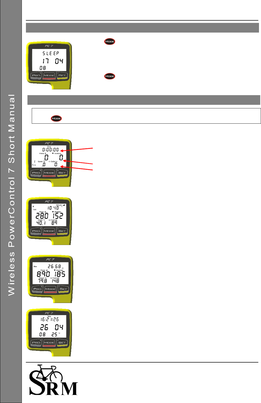
Press for 10 seconds to activate Sleep Mode.
The PowerControl 7 will not enter Sleep Mode while it is receiving data from
and of the sensors.
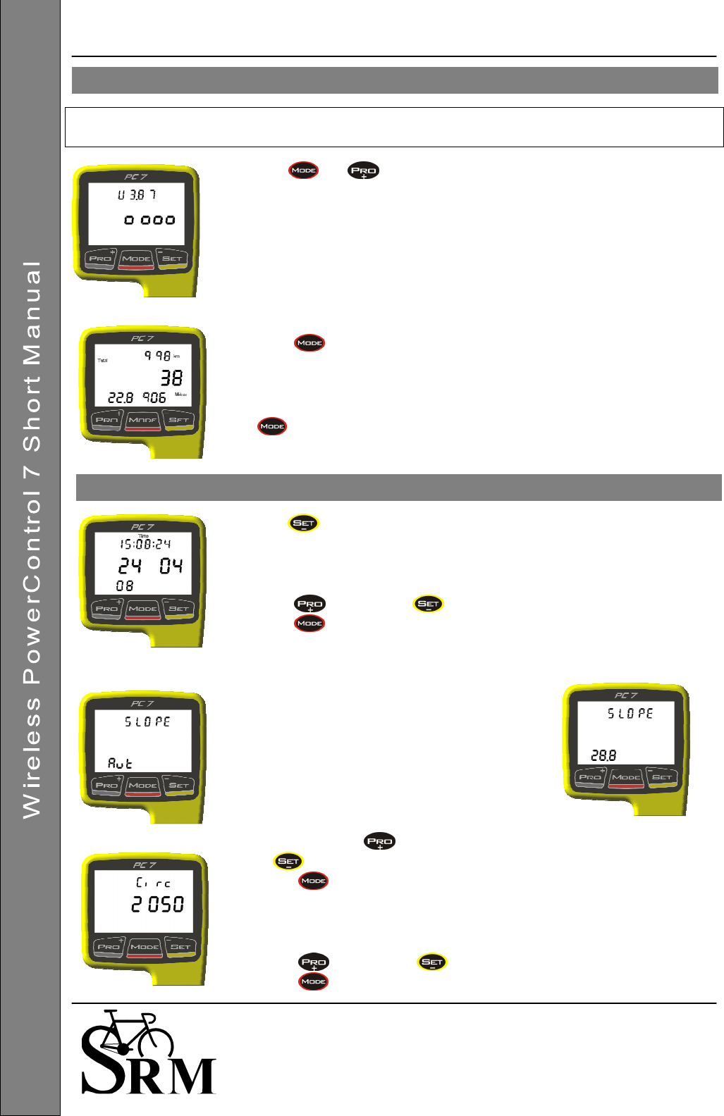
The PC 7 shows the date of the Firmware Release being used. (17.04.2008)
Press to wake up the PC 7.
The main menu shows real-time data as the athlete trains.
Press to change between the different information modes on your display.
Real-time training data Menu:
• Top Line: Training time, distance [miles or km], altitude [feet or m] or all
three alternating. (Settings for information which is shown can be
changed in the SRM Windows Software).
• Middle Line: Power [Watt] (> 1000W, 1.0 = 1000W), Heart rate [bpm]
• Bottom Line: Training zone, Speed [km/h or miles/h], Cadence [rpm]
If no signal from a sensor is picked up, the display shows “-“ for this data
instead of a number (for example “-“ speed if the speed sensor is not working).
Average training data Menu:
• Top Line: Training time, distance, ascending altitude or all three
alternating.
• Middle Line: Power, Heartrate
• Bottom Line: Speed, Cadence
Maximum training data Menu:
• Top Line: Mechanical energy uptake in kilojoules (kJ)
(Estimating an efficiency of 25% riding the bike, this is approximately
the same as the total energy burned by the athlete in kcal)
• Middle Line: Power, Heart rate
• Bottom Line: Speed, Cadence
Time/Date Menu
• Top Line: Time of day
• Middle Line: Day, Month
• Bottom Line: Year, temperature in Celsius or Fahrenheit
Main Menu: PowerControl
7
Sleep Mode
PowerControl 7: Getting Started 14 October 2008 2
Schoberer Rad Messtechnik GmbH
Rudolf Schulten Str. 6
D-52428 Jülich
Tel.: +49 (2461) 69123-0
Fax:+49 (2461) 69123-17
SRM Service Center Inc.
720 West Monument Street
Colorado Springs, CO 80904
USA
Tel.: +1 (719) 266 4127
Fax: +1 (710) 266 4284
www.srm.de
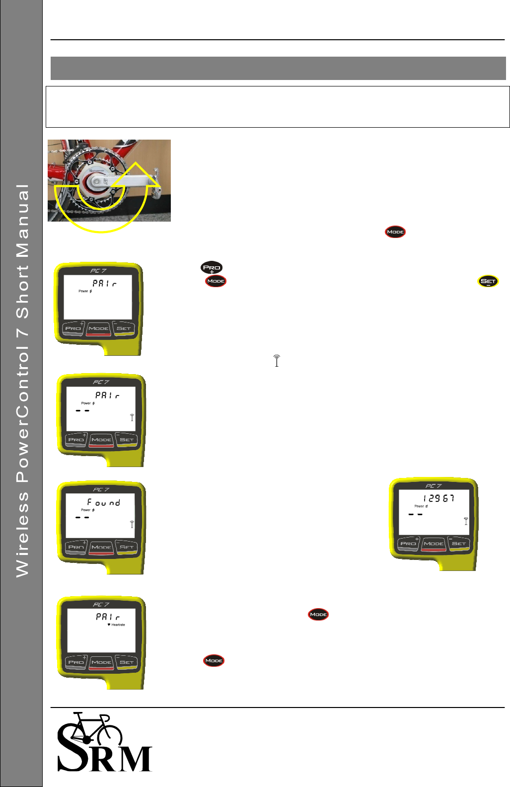
You need to pair the PowerControl 7 with the power, speed and heartrate sensors.
If you don’t do this, no data will be received by the PowerControl 7 for any of the sensors
that you want to use on your bike.
Pairing the sensors with the PowerControl 7 will only be possible if they are
switched on.
• Switch on the PowerMeter by pedaling the crank backwards a few times
(it will switch on when sensor in the PowerMeter passes the magnet
attached to the bottom bracket).
• Switch on the Speed sensor by spinning the wheel.
• Switch on Heart Rate sensor by putting the belt on your chest. To have a
better contact please moisten the electrodes.
• Switch on the PowerControl by pressing the button.
Hold for about 3 seconds to enter Sensor Pairing mode.
Press once quickly to select the device you want to pair and press
once quickly to tell the PC 7 to start searching.
The Antenna symbol blinking on the right of the display shows that the
searching process has started.
The search bar in the middle of the display shows the progress of the search.
If no signal is picked up, please check:
• If the sensor is switched on
• The position of the magnet
• If the battery is charged
• If it is still not working, please get in touch with the Service Center
If a Sensor is found, the PC 7 will show
“Found” in the Top line, alternating with the
Sensor’s Serial number.
If the pairing fails, please repeat step 1 and 2.
To pair another Sensor, press once quickly to get back to the device
selection Menu. Continue with pairing the Heartrate sensor and Speed
sensor.
Hold for about 3 seconds to leave the device pairing menu and go back
to the main menu.
Sensor Pairing
PowerControl 7: Getting Started 14 October 2008 3
Schoberer Rad Messtechnik GmbH
Rudolf Schulten Str. 6
D-52428 Jülich
Tel.: +49 (2461) 69123-0
Fax:+49 (2461) 69123-17
SRM Service Center Inc.
720 West Monument Street
Colorado Springs, CO 80904
USA
Tel.: +1 (719) 266 4127
Fax: +1 (710) 266 4284
www.srm.de
It is also possible to program the sensor identification numbers in the SRM Windows Software. This will make
the pairing unnecessary.
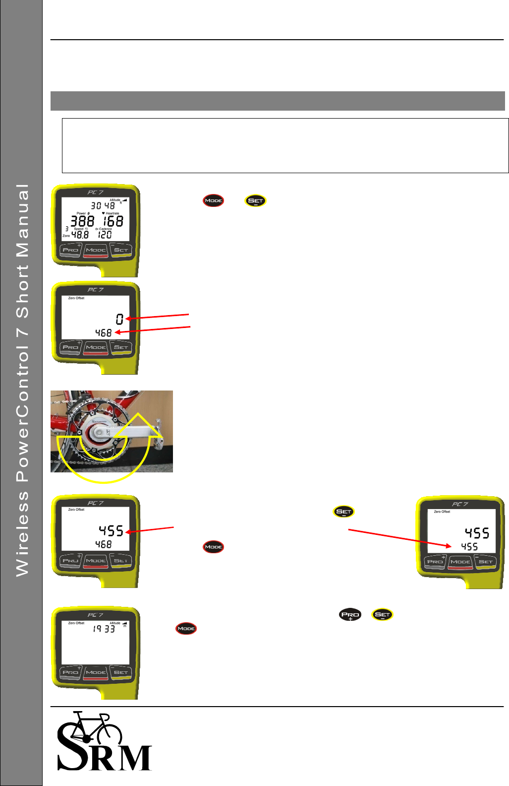
It is very important to set the Zero offset before each ride, so the PowerControl knows
the frequency output of the PowerMeter with no load on the chain.
Without a pre-ride zeroing, the measured power may be wrong.
Please pair the PowerMeter before, so that the signal is picked up!
Press and at the same time to enter the Zero Offset Menu.
The first screen shows the Zero Offset Menu for the PowerMeter.
There are 2 numbers on the display:
The top number is the real-time frequency output of the PowerMeter
The bottom number is the stored Zero Offset
If the top number is zero, turn the PowerMeter on by pedaling backwards.
Then, let go of the crank and make sure nothing is touching it.
If the top number is still Zero, please check:
• That the sensor is paired (see page 2)
• The position of the magnet
• If the battery is charged
• If it is still not working, please get in touch with the Service Center
After the top number stabilizes, press to store
the new Zero Offset of the PowerMeter.
Press to exit
You can adjust the Altitude by pressing or .
will bring you back to main menu.
The altitude measurement depends on the current weather conditions
(barometric pressure) and temperature, so it has to be calibrated before every
ride. HINT: Try checking Google Earth for the altitude to use for the calibration.
Setting the Zero Offset
PowerControl 7: Getting Started 14 October 2008 4
Schoberer Rad Messtechnik GmbH
Rudolf Schulten Str. 6
D-52428 Jülich
Tel.: +49 (2461) 69123-0
Fax:+49 (2461) 69123-17
SRM Service Center Inc.
720 West Monument Street
Colorado Springs, CO 80904
USA
Tel.: +1 (719) 266 4127
Fax: +1 (710) 266 4284
www.srm.de
In the SRM Windows Software, you can switch between feet or meters for measuring the altitude.
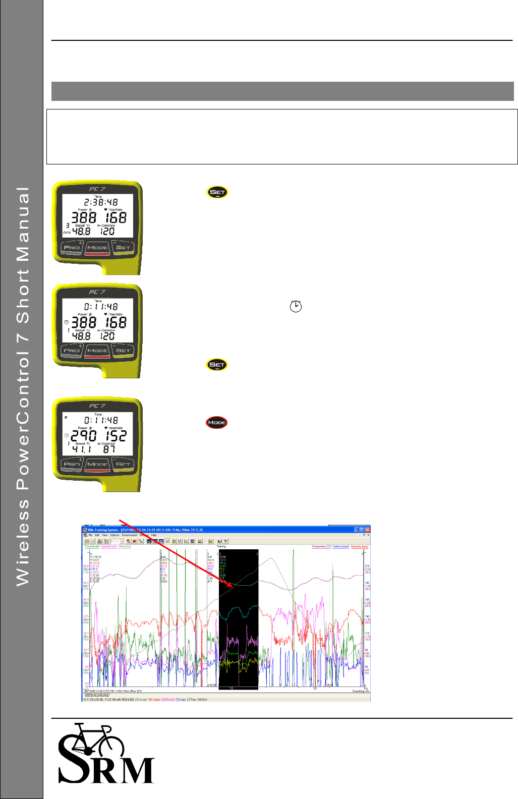
The Set Marker option is available to show data during intervals, to set file markers during a
training session, and for lap times.
After downloading the data to your PC with SRM Windows Software, you can see and edit
the sections where you have set markers, and review the data in detail.
Press to start the interval.
Time on the display will start with zero.
A blinking stopwatch icon appears.
The number of the interval is shown on the left below the stopwatch icon.
The maximum amount of markers shown on the display is 20, but more
markers can be stored and shown after downloading.
Press to stop the interval.
For 10 seconds, the display will show the average data from last interval.
Press to see the maximum data of the interval.
After 10 seconds, the display will switch back to main menu.
An Interval or Marker as it appears after downloading it into your SRM Windows Software
Set Markers during Training R
ide
s
/ Interval Training
PowerControl 7: Getting Started 14 October 2008 5
Schoberer Rad Messtechnik GmbH
Rudolf Schulten Str. 6
D-52428 Jülich
Tel.: +49 (2461) 69123-0
Fax:+49 (2461) 69123-17
SRM Service Center Inc.
720 West Monument Street
Colorado Springs, CO 80904
USA
Tel.: +1 (719) 266 4127
Fax: +1 (710) 266 4284
www.srm.de
The PowerControl 7 can be charged through the USB Adapter or the charging device.
The battery has no memory effect, and it can (and should) be recharged regularly.
Press and at the same time to enter the Battery Status Menu.
The first screen shows the charge status of the battery.
The top line shows the voltage.
The second line shows a graph of the charge status
(
= max charge)
Press to see the total amount of training.
• Total distance (km or miles)
• Total training hours
• Total mechanical energy uptake (MJoule or Kcal)
will bring you back to main menu.
Hold for about 3 seconds to enter the Setup mode.
The first screen shows the setup menu to change the time and date.
Blinking numbers show what can be changed (first seconds, then minutes,
hours, …)
Press to increase or to decrease the shown number.
Press to select the next step.
The second screen shows the setup menu for
the slope.
“Aut” (short for Automatic) sets the slope to the
preset value the PowerMeter sends to the
PowerControl 7.
The value is shown above “Aut” (without the
point).
It is also possible to change the slope manually
(for example after recalibration).
From “Aut” press to change the slope from 50.0 Hz/Nm downward
or from 0.0 Hz/Nm upward.
Press to select the next step.
The third screen shows the setup menu for the wheel circumference.
Press to increase or to decrease the value shown.
Press to select the next step.
Mode
–
Pro Menu
Setup Menu
PowerControl 7: Getting Started 14 October 2008 6
Schoberer Rad Messtechnik GmbH
Rudolf Schulten Str. 6
D-52428 Jülich
Tel.: +49 (2461) 69123-0
Fax:+49 (2461) 69123-17
SRM Service Center Inc.
720 West Monument Street
Colorado Springs, CO 80904
USA
Tel.: +1 (719) 266 4127
Fax: +1 (710) 266 4284
www.srm.de
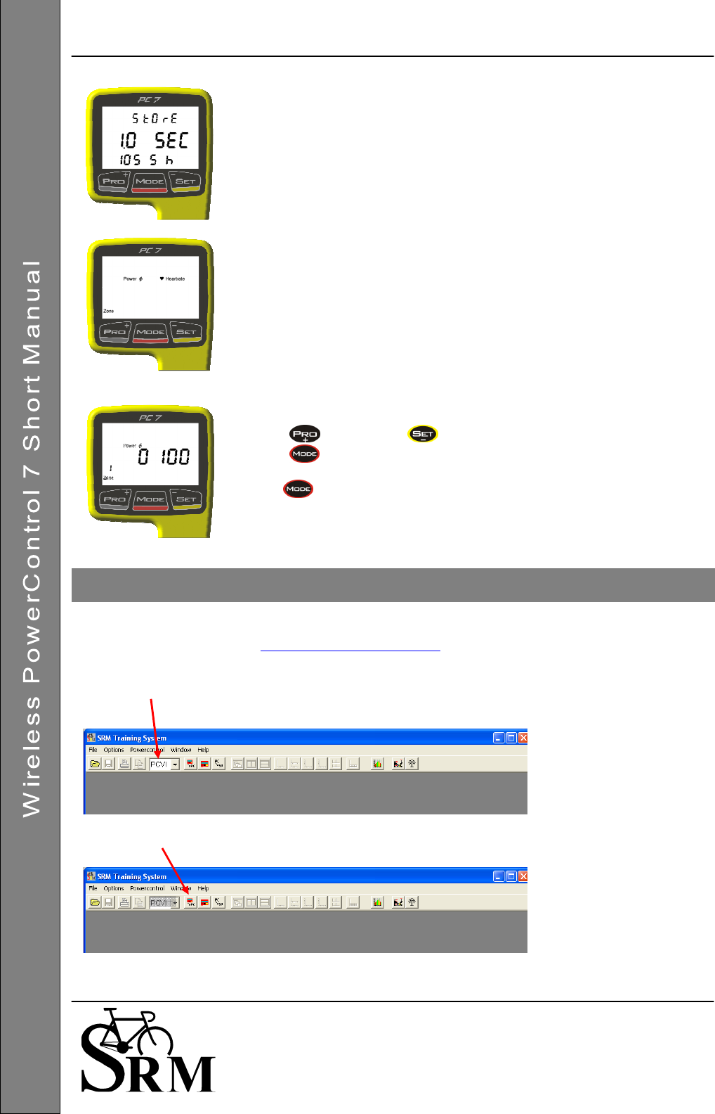
The fourth screen shows the setup menu for data storage.
The storage interval can be set between 0.5 and 5.0 sec.
By increasing or decreasing the storage interval, you will also increase or
decrease the amount of memory available.
For example, a storage interval of 1 second the memory will hold about 1054
hours, while a storage interval of 2 seconds will hold about 2108 hours.
The fifth screen offers the possibility to choose the settings for training zones
defined with heart rate (bpm) or power (watts).
These can also be set through the SRM Windows Software.
Threshold values from exercise tests (lab or field tests) can be used to define
these values and increase quality of your individual training.
The sixth to tenth screen shows the setup for training zone 1 to 5.
Press to increase or to decrease the value shown.
Press to select the next step.
Hold for about 3 seconds to leave the setup menu and go back to the
main menu.
To download your training and setup the PowerControl 7 on your Computer, please download the new SRM
Windows Software version (see www.srm.de/usa/software.html).
Start the software and plug in the PowerControl 7 with the USB adapter cable.
Once the PC 7 is attached to USB, the PC 7 box will go from black to grey indicating the software recognized
the PC 7 and the USB cable.
To download your training press the download button
SR
M
W
IN
Soft
w
are
Zur Anzeige wird der QuickTime™
Dekompressor „“
benötigt.
PowerControl 7: Getting Started 14 October 2008 7
Schoberer Rad Messtechnik GmbH
Rudolf Schulten Str. 6
D-52428 Jülich
Tel.: +49 (2461) 69123-0
Fax:+49 (2461) 69123-17
SRM Service Center Inc.
720 West Monument Street
Colorado Springs, CO 80904
USA
Tel.: +1 (719) 266 4127
Fax: +1 (710) 266 4284
www.srm.de
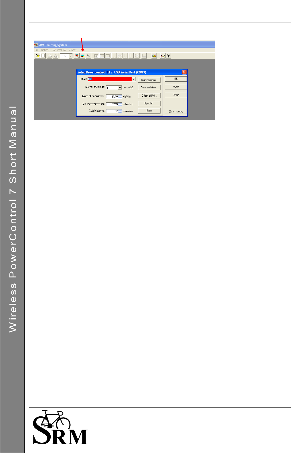
To setup your PowerControl 7 press the setup button
Please setup:
- Your initials (up to 20 characters).
- The interval of storage (seconds)
The slope of the PowerMeter can be set up manually or automatically (if you set the slope to 0.00 Hz/Nm,
the PowerControl will pick up the preprogrammed slope of the PowerMeter).
Regulatory Compliance FCC ID: WCS-PC7 IC: 7761A-PC7
This device complies with part 15 of the FCC Rules, Industry Canada RSS-210,
and
ICES-003. Operation is subject
to the following two conditions:
1. this device may not cause harmful interference, and
2. this device must accept any interference received, including interference that may cause undesired operation.
This equipment has been tested and found to comply with the limits for a Class B digital device, pursuant to part 15 of
the FCC rules. These limits are designed to provide reasonable protection against harmful interference in a
residential installation. This equipment generates, uses, and can radiate radio frequency energy and may cause
harmful interference to radio communications if not installed and used in accordance with the instructions. However,
there is no guarantee that interference will not occur in a particular installation. If this equipment does cause harmful
interference to radio or television reception, which can be determined by turning the equipment off and on, the user is
encouraged to try to correct the interference by one of the following measures:
• Reorient or relocate the receiving antenna.
• Increase the separation between the equipment and the receiver
• Connect the equipment into an outlet that is on a different circuit from unit.
• Consult the dealer or an experienced radio/TV technician for help.
This product does not contain any user-serviceable parts. Repairs should only be made by an authorized SRM
service center. Unauthorized repairs or modifications could result in permanent damage to the equipment, and void
your warranty and your authority to operate this device under Part 15 regulations.