SRT Acquisition RUCPI Base Station Transceiver User Manual Customer Premise Installation
SRT Acquisition Base Station Transceiver Customer Premise Installation
Installation manual

NERA Telecommunications PRELIMINARY
Customer Premise Installation Issue #0.1, September, 2000
Preliminary Document – Not for Duplication
Page 1 of 9
1 CUSTOMER PREMISE INSTALLATION: Velocity2000™ WLL
System
1.1 General
This document provides installation and reference information for the Customer Premise
components of the Velocity2000™ Wireless Local Loop System. Components included
are: the Radio Unit (RU), Digital Radio Link (DRL)(Cable), and the Customer Premise
Interface (CPI).
1.1.1 Radio Unit (RU)
The Radio Unit (RU) provides a remote wireless interface between the customer
premises and the Host Digital Terminal (HDT) that is fully synchronized to the network
interface at the base station. The RU is mounted either directly to the customer premise,
on a freestanding mast, or on a mast mounted to the customer premise.
The RU is an outdoor, environmentally sealed antenna, housed in a plastic radome. The
antenna is attached to the back plate casting. An o-ring seals the entire unit to the
radome. The access panel has an attached environmental/EMI gasket. The CPI
interface cable (DRL) enters through a watertight squeeze grip on the access panel. The
cable interfaces to the antenna via a seven-position connector (16 AWG max). A ground
lug is attached to the external back plate casting and accepts 14-6 AWG aluminum or
copper ground wire. A “valve” on the access panel allows water vapor to escape. The
sun shield is attached to the back plate along with a variety of mounting brackets (pole
and flat surface mount). The unit is 10.65 inches x 4.05 inches x 9.65 inches and weighs
6 pounds. The unit dissipates approximately eight (8) watts.
1.1.2 Digital Radio Link (DRL)
The Digital Radio Link (DRL) is a 6-wire cable, with an embedded RS422 serial interface,
that connects the RU to the CPI. This cable consists of shielded twisted pairs (signal
lines) along with power and ground conductors. The DRL provides both power and
digital links to the CPI in addition to lighting protect termination.
Note: An additional lightning ground wire must be run from the RU to earth ground along
the shortest possible path.
1.1.3 Customer Premise Interface (CPI)
The power supply is a 150W 48-volt dual input, redundant 5V/1.2V out-switching supply.
The power supply connects to the backplane with a DIN standard, type F connector. The
supply provides alarms for excess temperature, current, and voltage. A temperature
sensor on the PS controls the fan activation. The power dissipated by a single supply
(not sharing) is 37W.
2 RADIO UNIT (RU) INSTALLATION
2.1 Location
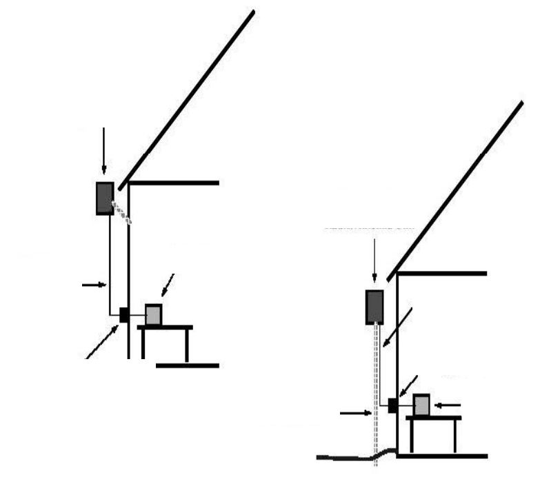
Survey the exterior of the Customer Premise site for a location that will provide line-of-
sight (LOS) communication with the Central Office (CO) or the Radio Base Station
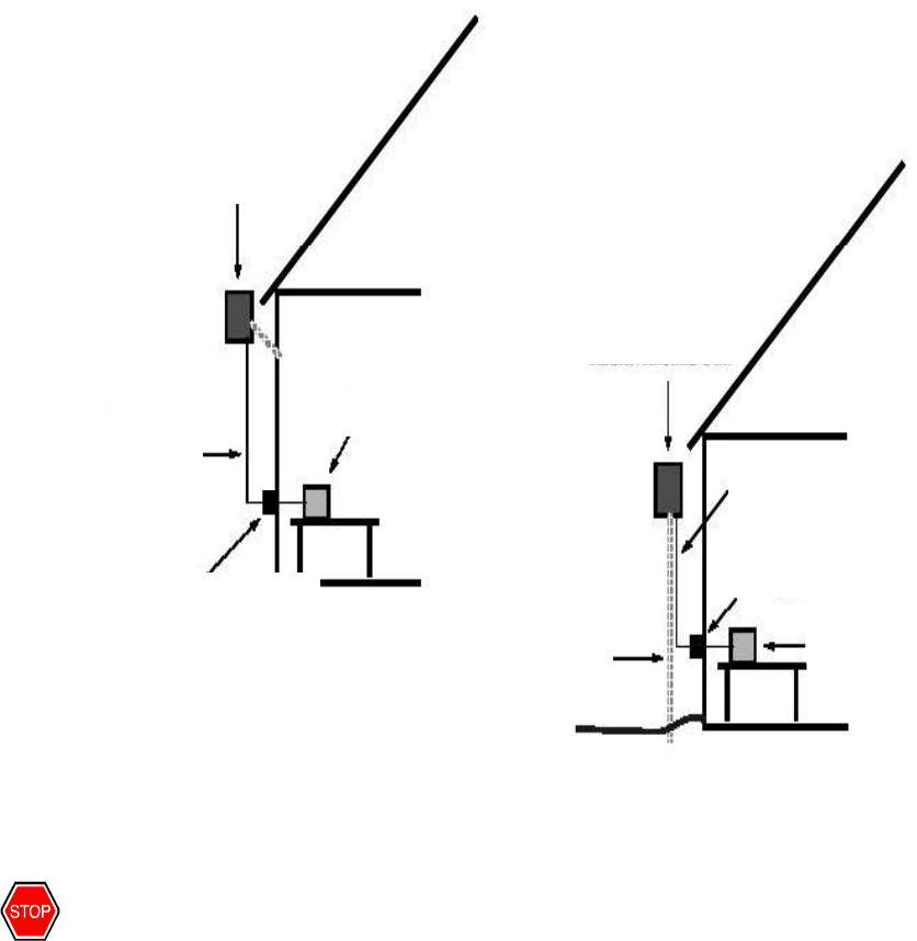
Controller location, where the Radio Base Station Antenna is mounted. Figure 1 shows
typical installations.
NERA Telecommunications PRELIMINARY
Customer Premise Installation Issue #0.1, September, 2000
Preliminary Document – Not for Duplication
Page 2 of 9
Care must be taken to determine how the DRL will be run to the CPI and how a separate
ground wire will be run to earth. Avoid too many cable bends. Avoid power lines. Avoid
signal lines. The separate ground wire must be run as straight as possible from the RU
directly to earth. Listed are three mounting options to choose from in determining which
mounting configuration to use.
1. Use the highest point of the Customer Premise for LOS operation and choose a flat
surface on which to mount the RU.
2. Install (or have installed), a freestanding vertical pole next to the Customer Premise
(if it is deemed necessary), to obtain the appropriate height for LOS operation. (Obey
local codes for the installation of such a mount.)
3. Install (or have installed), a vertical pole directly onto the Customer Premise (if it is
deemed necessary), to obtain the appropriate height for LOS operation. (Obtain the
Customer’s permission for this installation and obey local codes for such a mount.)
Refer to Figure 1 to view the typical installation.
Figure 1 – Typical Installation
2.2 Mount
2.2.1 Flat Surface
Using the template supplied with the RU, determine the mounting hole positions on the
flat surface, which correspond to the slots on the back of the RU. Determine the type of
Lightning protection
Shielded
Twisted-
pair
Wiring
CPI Box
Wall
-
mounted
Radio/Antenna Unit
Mast
-
mounted
Radio/Antenna Unit
Mast in ground
Shielded
Twisted-pair
Wiring
Lightning protection
CPI Box
DRL
DRL
NERA Telecommunications PRELIMINARY
Customer Premise Installation Issue #0.1, September, 2000
Preliminary Document – Not for Duplication
Page 3 of 9
anchor appropriate to the surface on which the RU will be mounted (wood screws, lag
screws, expandable anchors, etc.).
Note: The RU must endure potentially severe winds and weather. The mount must be
secure enough to prevent any movement.
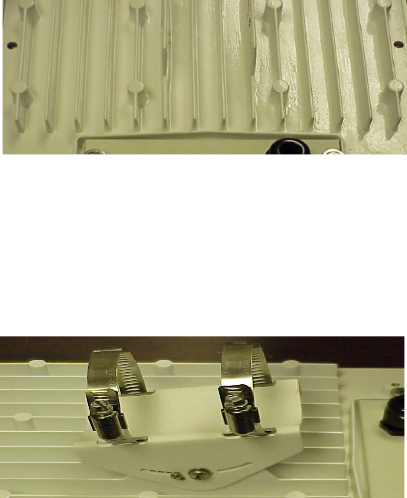
Temporarily place the RU onto the screw heads and prepare to measure distance from the
RU terminal connector and ground block, to their far-end terminations at the CPI and earth
ground rod, respectively. Figure 2 shows the flat surface-mount points.
Figure 2 – Flat Surface Mount Points
2.2.2 Vertical Pole
Attach the supplied Pole Mount Hardware to the back of the RU with the fasteners
provided. The screw adjustable pole clamps are designed to fit poles up to three (3)
inches in diameter.
NOTE: The RU must endure potentially severe winds and weather. The mount must be
secure enough to prevent any movement. Be certain that the RU will not rotate on the
pole, or slide downward.
Temporarily place the RU onto the pole and prepare to measure distance from the RU
terminal connector and ground block, to the far-end terminations at the CPI and earth
ground rod, respectively. Figure 3 shows the mounting clamp assembly.
Figure 3 – Vertical Pole Mount Assembly
NERA Telecommunications PRELIMINARY
Customer Premise Installation Issue #0.1, September, 2000
Preliminary Document – Not for Duplication
Page 4 of 9
3 ESD PROCEDURE
3.1 General
When you see this symbol be aware that you are working with ESD-sensitive
components. Take the prescribed precautions.
3.1.1 Wear A Grounding Wrist Strap
Wear a grounding wrist strap when installing or removing components.
NOTE: To properly use a grounding wrist strap, perform the following test using an
ohmmeter:
• Set the ohmmeter to the maximum resistance scale
• Connect one meter-lead to the contact point of the wrist strap and the other lead to
the clip or banana plug on the far end of the wrist strap. Hold one lead (not both)
while performing this measurement.
A resistance reading in the vicinity of 1 megohm (one million ohms) indicates that the
wrist strap is acceptable. A reading of less than 900,000 ohms indicates that the wrist
strap is inadequate and may not provide proper protection. An “open” reading indicates
that the internal resistance of the wrist strap has failed and it will not protect the
equipment from ESD damage.
3.2 Use
Attach the wrist strap securely to your wrist and clip the end to a ground post on the
equipment rack or elsewhere on the metal mounting assembly. (Alternatively, insert the
banana plug into the jack provided on the equipment rack or metal mounting assembly.)
Momentarily touch the grounded equipment rack to discharge any static build-up before
handling modules or other static sensitive devices. Momentarily touch the anti-static
storage bag to the grounded equipment rack before removing or re-inserting a
component. Always store unused or spare ESD-sensitive devices and components in
their original anti-static storage bags.
DO NOT touch any circuit traces or board components during installation. Hold the
boards and assemblies by the front panel or by the board edges.
3.3 Optional Lightning Protection
Any outdoor mounted electrical device is subject to lightning strikes. The Velocity2000™
WLL System, in its basic configuration, is fully lightning protected. However, for those
who require additional protection, this Optional Lightning Protection scheme is provided.
NOTE: An earth ground point is defined as one that connects directly to the earth by
means of a highly conductive (copper, et. al.), rod or plate, buried into the earth at a
depth specified by local codes.
1. Choose the most direct path from the RU ground lug to an earth ground point. Avoid
sharp bends and frequent turns.
2. Run a 14-6 AWG copper or aluminum ground wire, from the ground lug on the RU, to
the earth ground point.
3. Attach a ground clamp to the earth ground point and connect the ground wire to this
clamp.
NERA Telecommunications PRELIMINARY
Customer Premise Installation Issue #0.1, September, 2000
Preliminary Document – Not for Duplication
Page 5 of 9
Recommended suppliers for Optional Lightning Protection products:
• Transtector Phone 208-762-6069
• Zap-Tech Phone 775-588-4040
4 ELECTRICAL CONNECTION
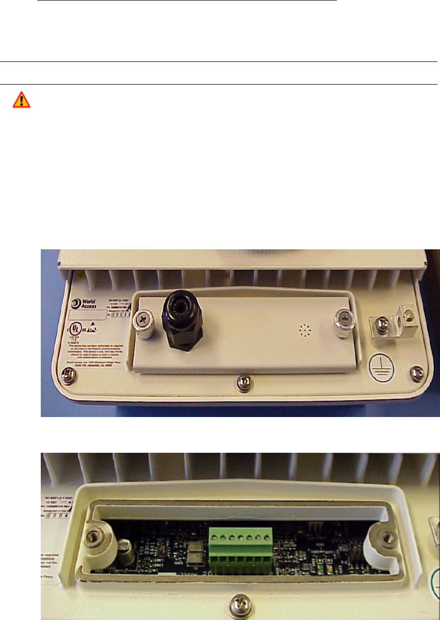
The RU/CPI interface cable (DRL) enters the RU through a watertight “squeeze grip”
bushing on the access panel. The terminal block inside of the RU, is wired to the DRL by
first removing the access panel, passing the DRL through the bushing, then reattaching
the panel. Follow the following steps and refer to Figures 4 and 5.
1. Loosen the thumbscrews on either side of the access panel and remove the panel.
2. Loosen and remove the squeeze grip nut.
3. Slide the squeeze grip nut over the free end of the DRL.
4. Pass the DRL through the squeeze grip assembly on the access panel.
5. Position the squeeze grip nut back onto the assembly, but do not tighten.
6. Strip the ends of the six leads in the DRL.
Figure 4 – Access Panel
Figure 5 – Terminal Block

NERA Telecommunications PRELIMINARY
Customer Premise Installation Issue #0.1, September, 2000
Preliminary Document – Not for Duplication
Page 6 of 9
7. Wire the DRL leads, using the legend screened on the RU printed circuit board as a
guide.
8. Slide the access panel back into position, removing slack from the DRL as you go.
9. Tighten the thumbscrews of the access panel.
10. Tighten the squeeze grip nut.
11. Attach the free end of the separate ground wire to the ground lug on the RU cabinet.
(See “Optional Lightning Protection” below.)
12. Reattach the RU to its mount (surface or pole).
13. Dress the DRL and ground wire down and away from the RU, using cable clamps or
cable ties as necessary.
5 DRL INSTALLATION
5.1 Cable Route
The Digital Radio Link (DRL) cable carries critical digital information and power between
the CPI and the RU. The cable is shielded and internally grounded to protect signals
from outside interference, however it is prudent to route the DRL in such a way as to
avoid proximity with sources of potential interference. The route will vary from one
installation to another.
The ideal route for the DRL, is a simple straight line from the RU to the CPI however, this
is not always possible. In planning a specific route, try to avoid sharp, right angle bends.
Do not place the DRL under or near heavy items that may shift with time. Any kink or
pressure on the cable will degrade or interrupt the signal and power flow.
Use cable clamps or cable ties to keep the DRL from shifting in the wind or rubbing
against hard or rough surfaces.
Do not allow the cable’s own weight to apply stress to any one point. Support the DRL
with cable ties wherever it’s own weight will pull with any meaningful force.
Use a “feed through” where the DRL enters the Customer Premise. Apply the
recommended weather stripping for the chosen feed through.
Check the entire length of the DRL for breaks or damage to the outside covering.
Replace the cable if damage is found. Do not attempt to “tape” damaged areas.
The separate ground wire may parallel the DRL, but should not be attached to it via cable
clamps or cable ties. DO NOT twist the DRL cable and ground wire together at any point
along the route.
6 CPI INSTALLATION
6.1 Location
Survey the interior of the Customer Premise site for a location that will provide easy
access to the entry port of the DRL. This location should also facilitate easy access to
the Customer Premise Equipment (CPE), which will be connected to the CPI. Figure 6
shows typical installations.
Select a mounting location away from heat sources, electrical interference, and RF
interference.
NERA Telecommunications PRELIMINARY
Customer Premise Installation Issue #0.1, September, 2000
Preliminary Document – Not for Duplication
Page 7 of 9
Figure 6 – CPI Installation
6.2 Mount
WARNING: To comply with the FCC RF exposure operating configurations, the antenna
shall be mounted to ensure the antenna/person separation distance of at least 2 meters.
The CPI can be mounted to a flat vertical surface (wall, cabinet, etc.) or simply placed
upon a table or on the floor. For wall mounting, follow these steps while referring to
Figures 7 and 8:
Using the template supplied with the CPI, locate the mounting hole positions on the wall,
which correspond to the slots on the back of the CPI. Determine the type of anchor
appropriate to the surface on which the CPI will be mounted (wood screws, lag screws,
expandable anchors, etc.).
NOTE: The CPI will be connected to both the DRL and CPE cables and must therefore
be able to withstand some “tugging” stresses. The mount must be secure enough to
prevent any movement.
Install the top two anchors, making sure they are level horizontally. Hang the CPI from
these anchors to confirm both that the unit is level and that its proximity to all connecting
cables. Adjust the mounting location as necessary.
Lightning protection
Shielded
Twisted-
pair
Wiring
CPI Box
Wall
-
mounted
Radio/Antenna Unit
Mast
-
mounted
Radio/Antenna Unit
Mast in ground
Shielded
Twisted-pair
Wiring
Lightning protection
CPI Box
NERA Telecommunications PRELIMINARY
Customer Premise Installation Issue #0.1, September, 2000
Preliminary Document – Not for Duplication
Page 8 of 9
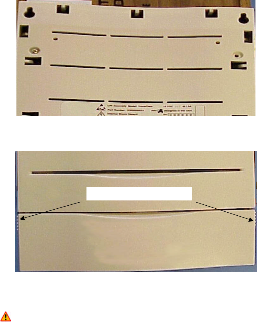
Figure 7 – CPI Mounting Points
Dismount the unit, install the remaining anchors, and open the front access panel
(Figure 8).
Figure 8 – Front Access Panel
6.3 Electrical Connection
The RU/CPI interface cable (DRL) enters the CPI through the bottom/left corner of the cabinet.
A standard bushing holds the cable in place once the cover is replaced. The terminal block
inside of the CPI, is wired to the DRL by first removing the access panel, passing the DRL
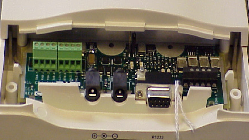
through the bushing, then reattaching the panel. Follow the steps below and refer to Figure 9:
1. Place hands on either side of the access panel and pull down on the panel.
2. Strip the ends of the six leads in the DRL.
3. Wire the DRL leads, using the legend screened on the CPI printed circuit board as a
guide.
4. Dress the DRL down and away from the RU, using cable clamps or cable ties as
necessary.
Slide down on both sides
NERA Telecommunications PRELIMINARY
Customer Premise Installation Issue #0.1, September, 2000
Preliminary Document – Not for Duplication
Page 9 of 9
Figure 9 – Terminal Block
5. Replace the access cover and reattach the CPI to its mount.
6. Attach the power supply connector plug to the jack at the bottom of the cabinet.
7. Attach the Customer Premise Equipment (CPE) to the RS232 connector at the
bottom of the cabinet.
8. Refer to the Turn-Up and Operation documents.