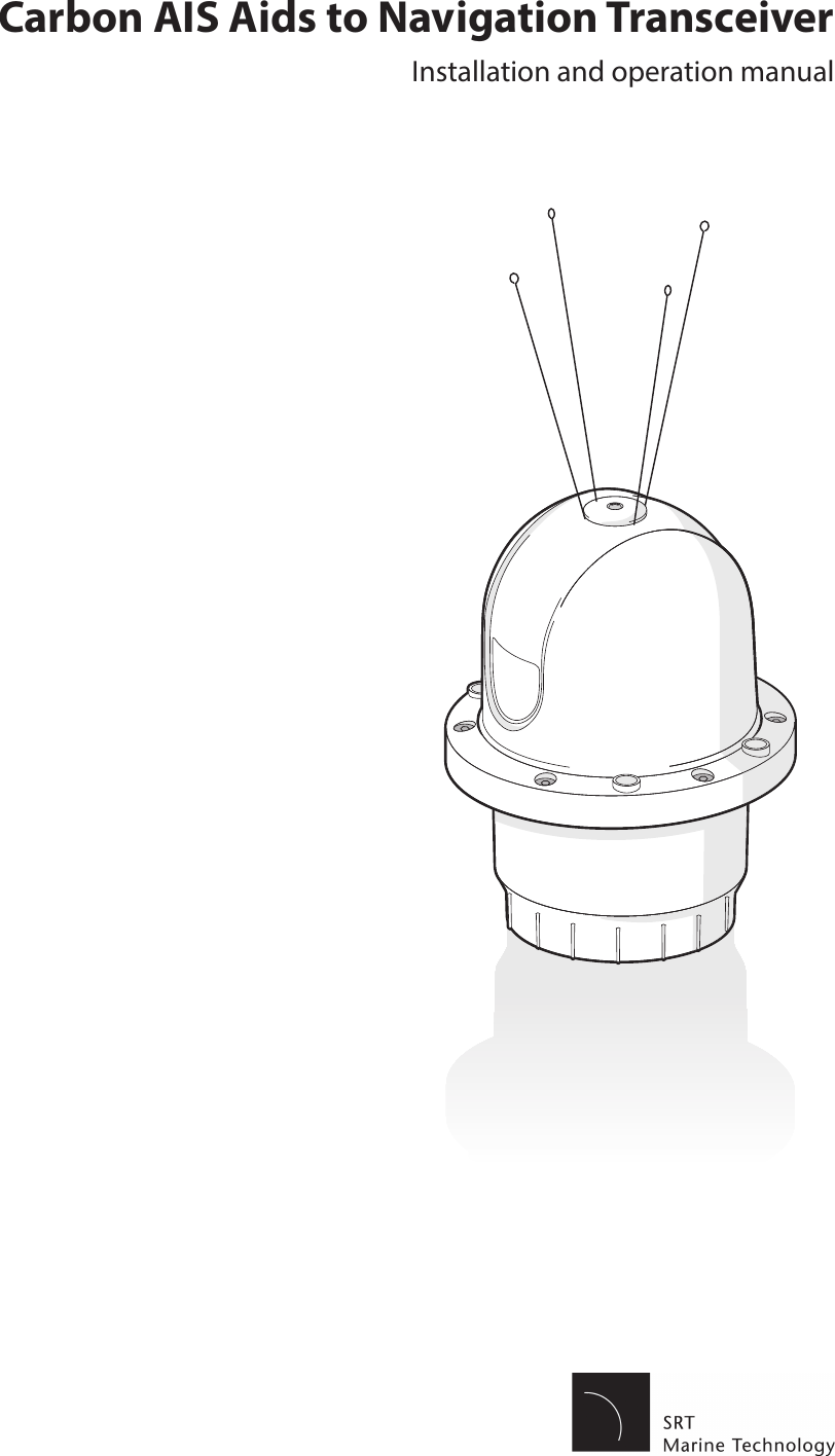
SRT Marine Systems plc 4180003 Carbon AIS Aid to Navigation Transceiver User Manual Carbon manual

Software Radio Technology plc Carbon AIS Aid to Navigation Transceiver Carbon manual

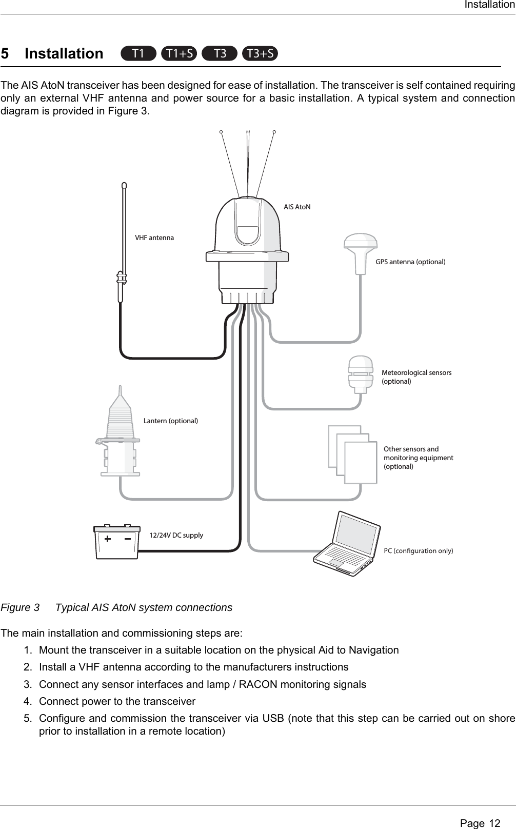
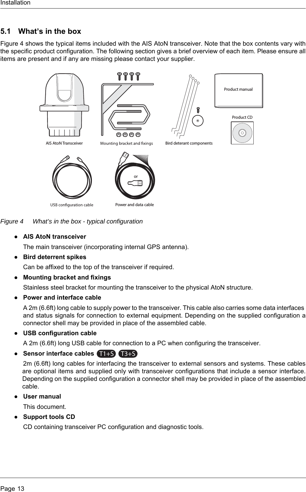
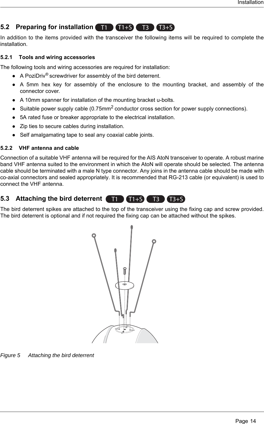
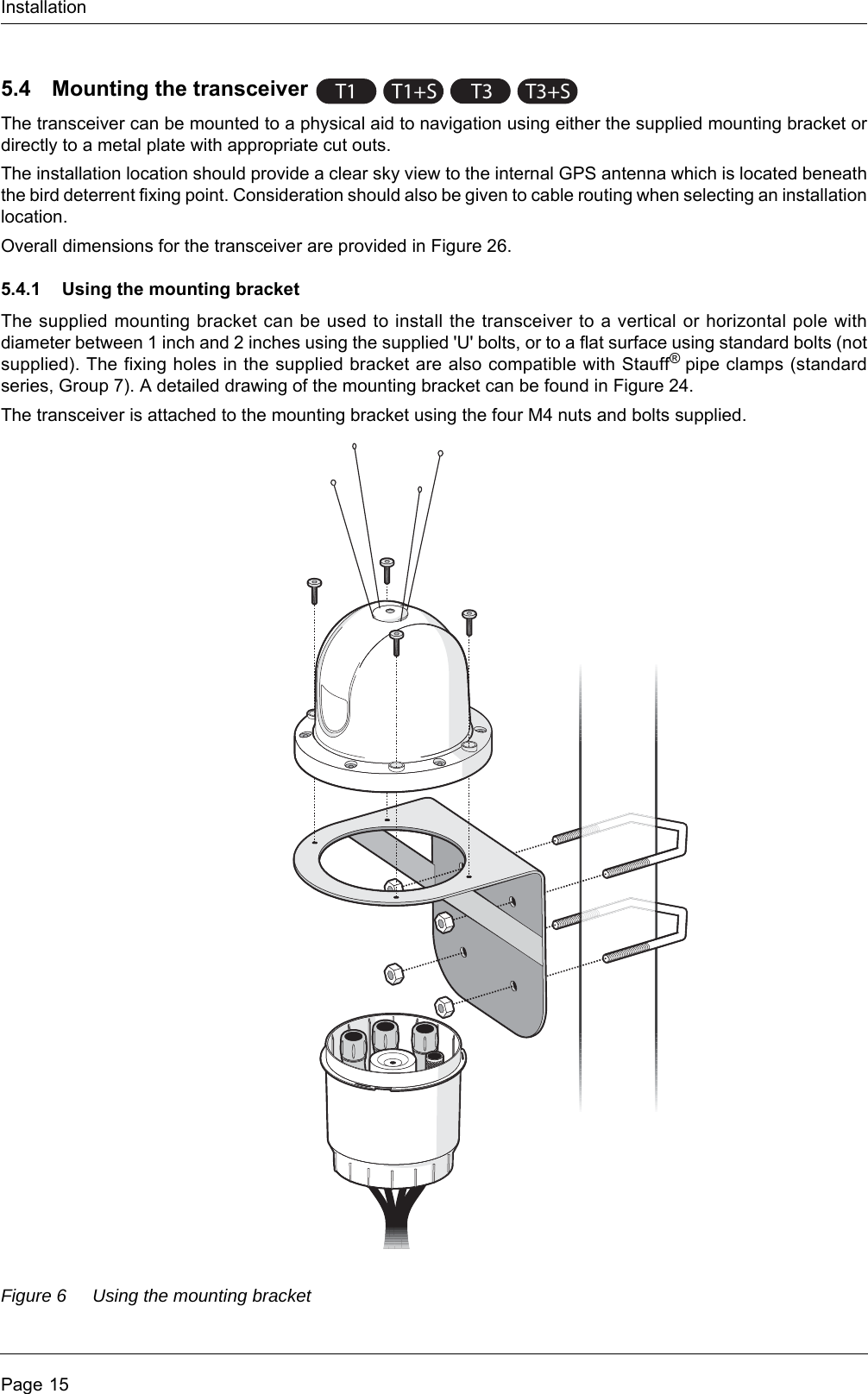
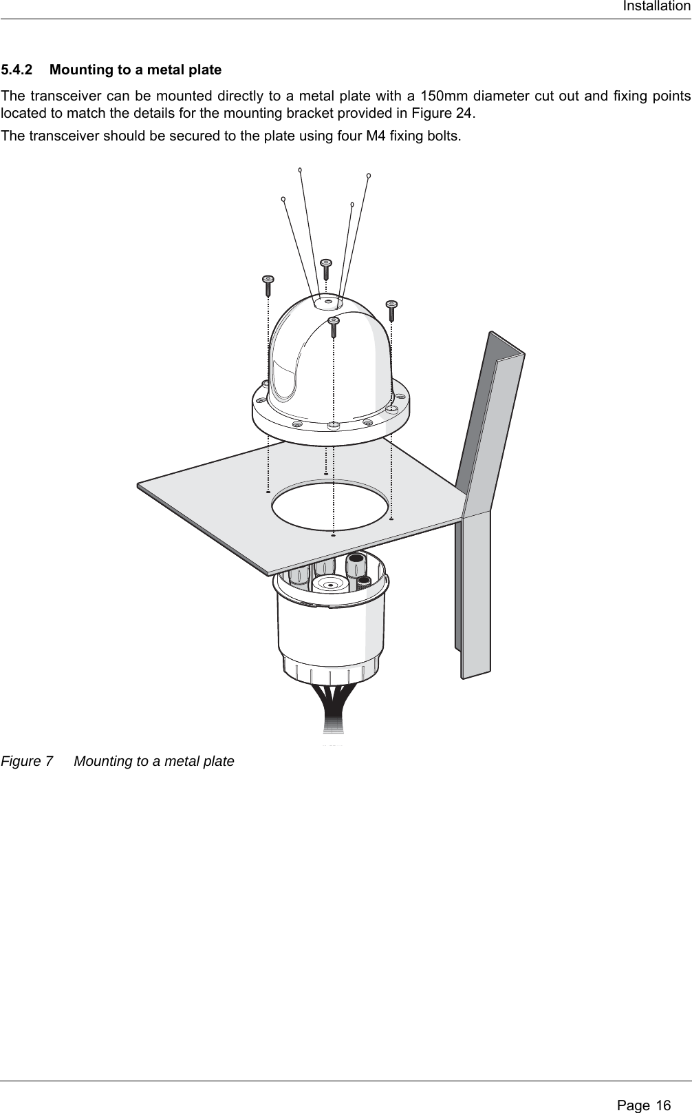
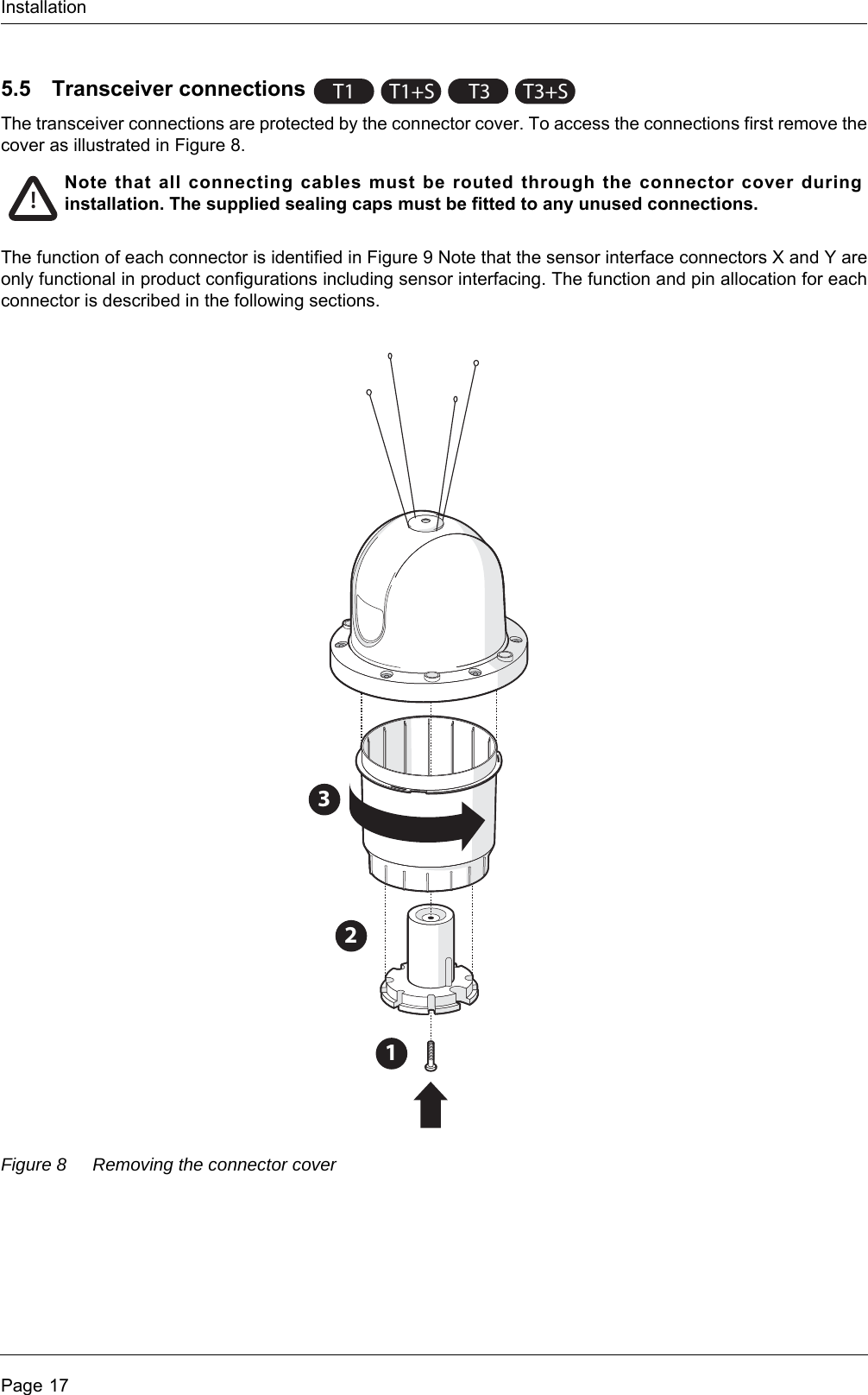
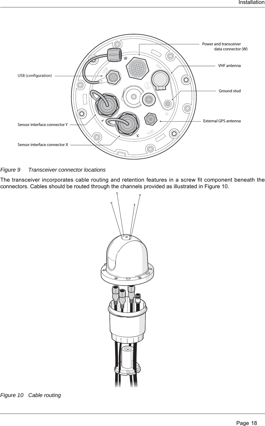
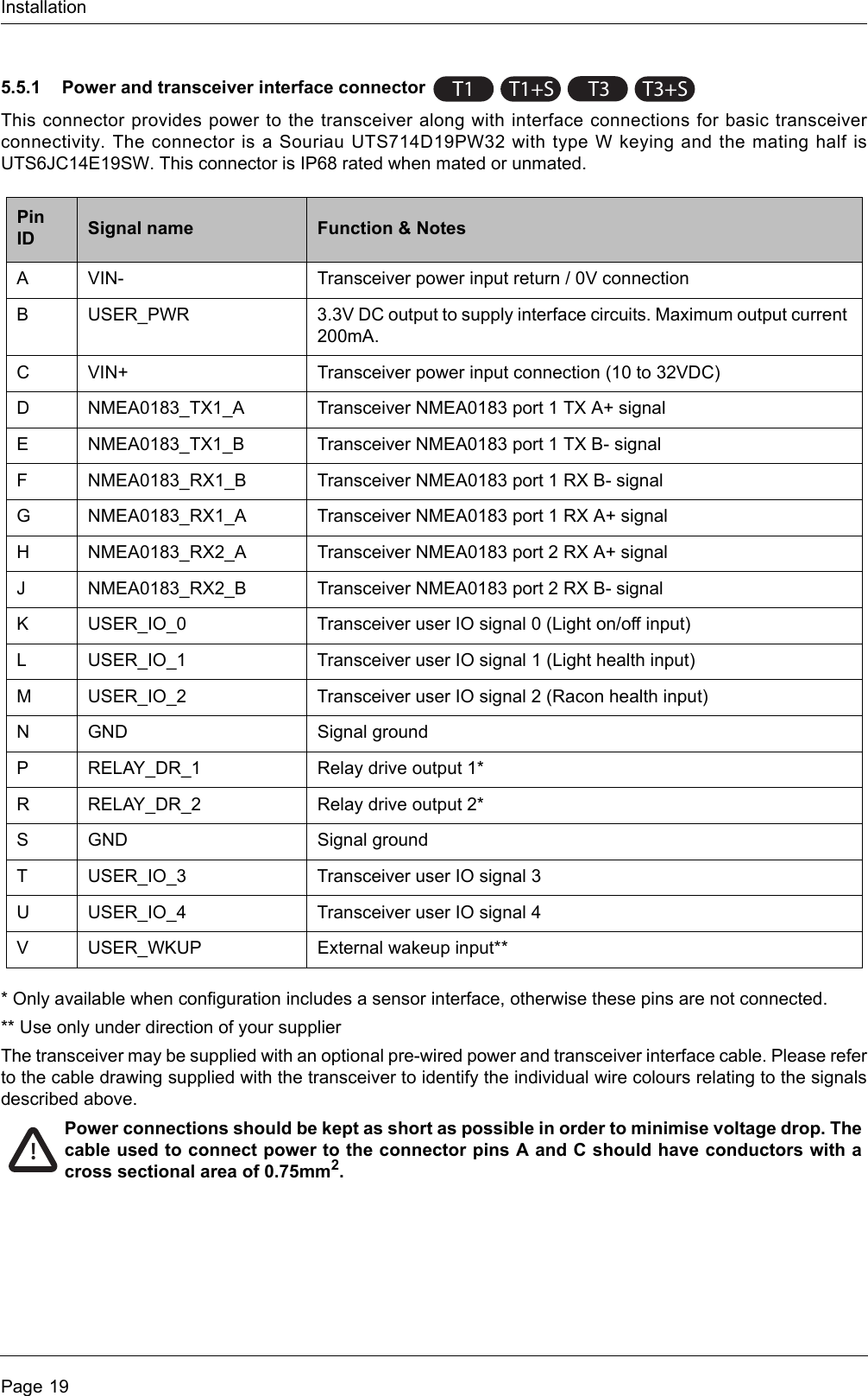
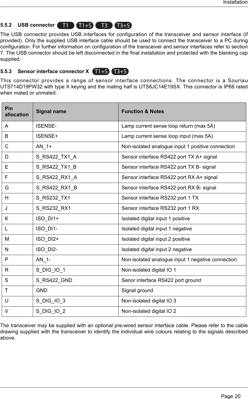
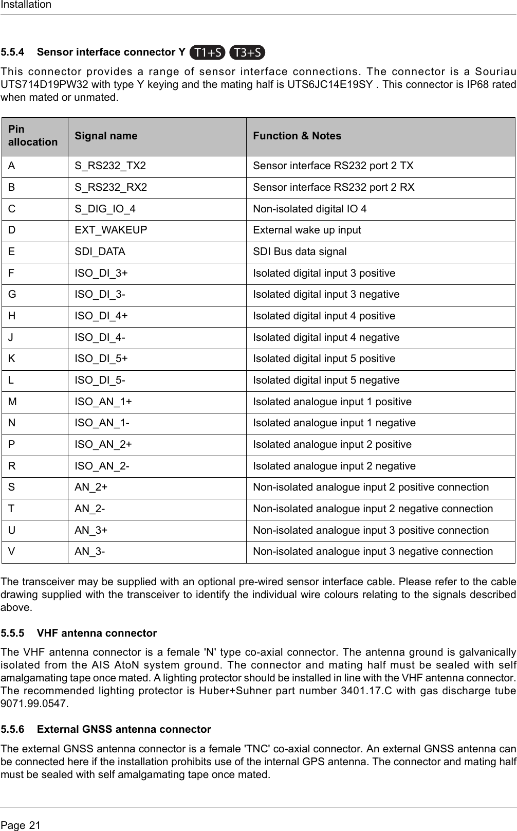
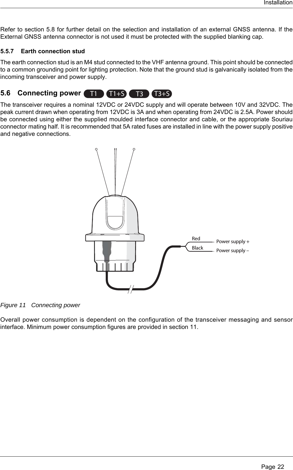
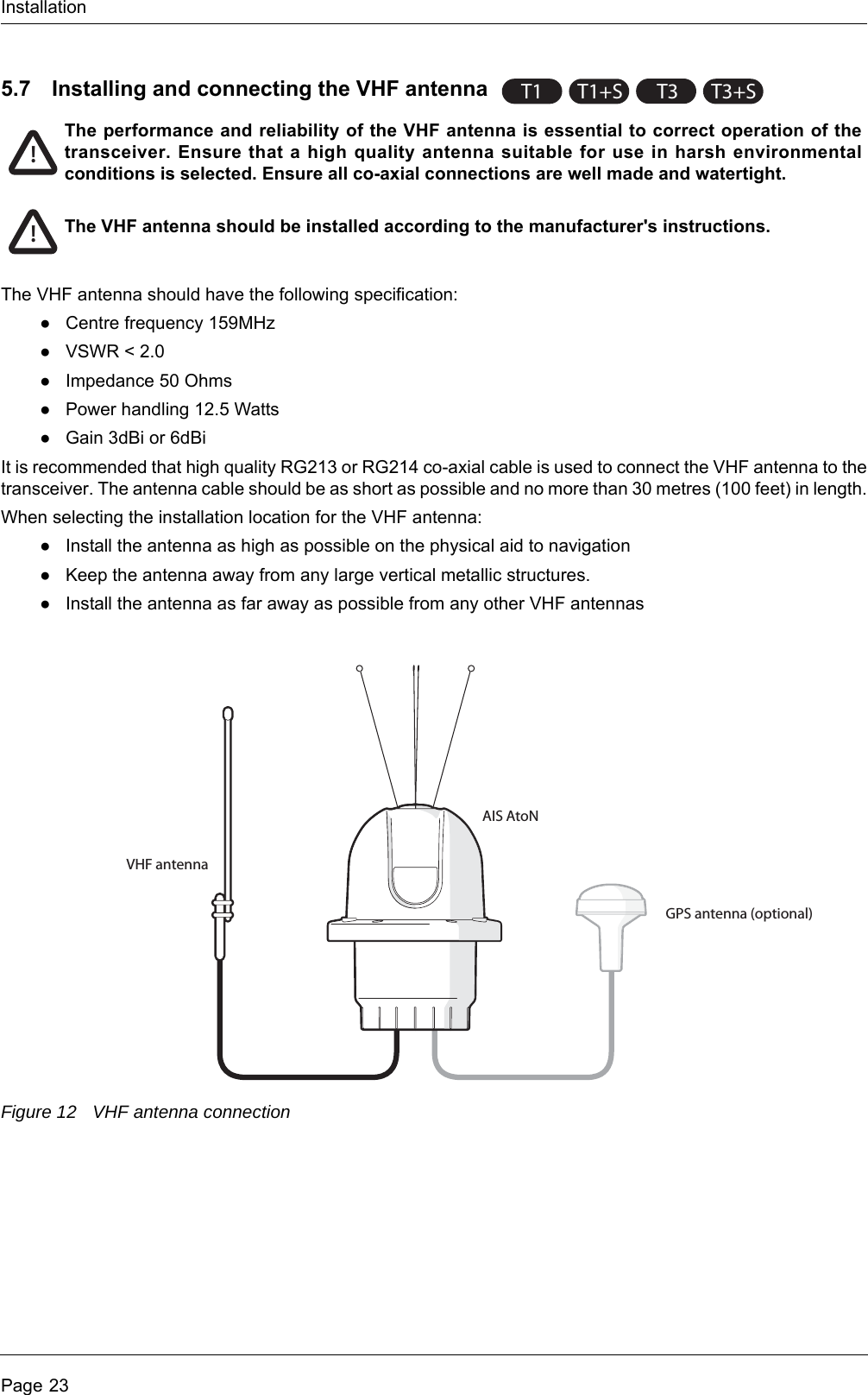
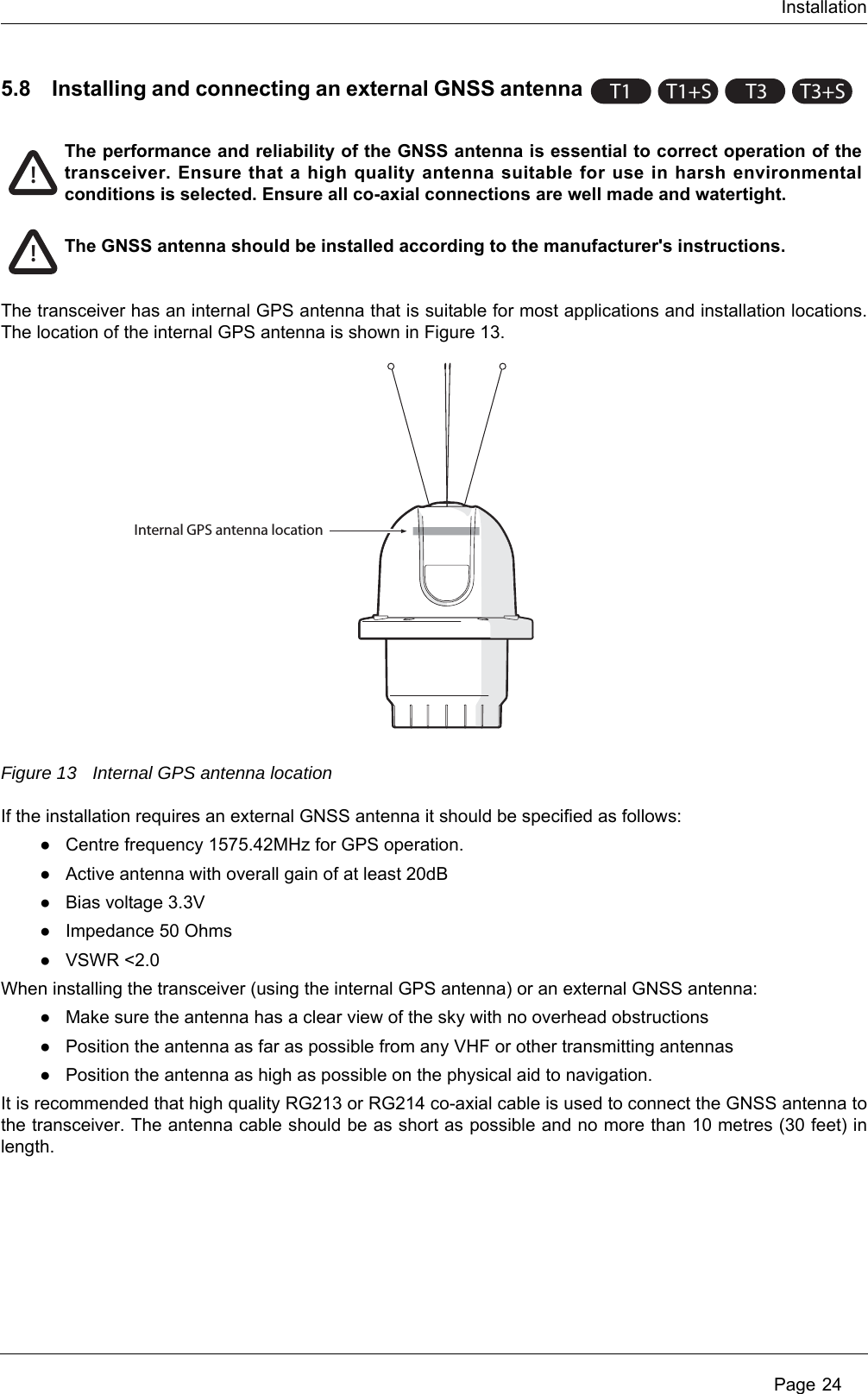
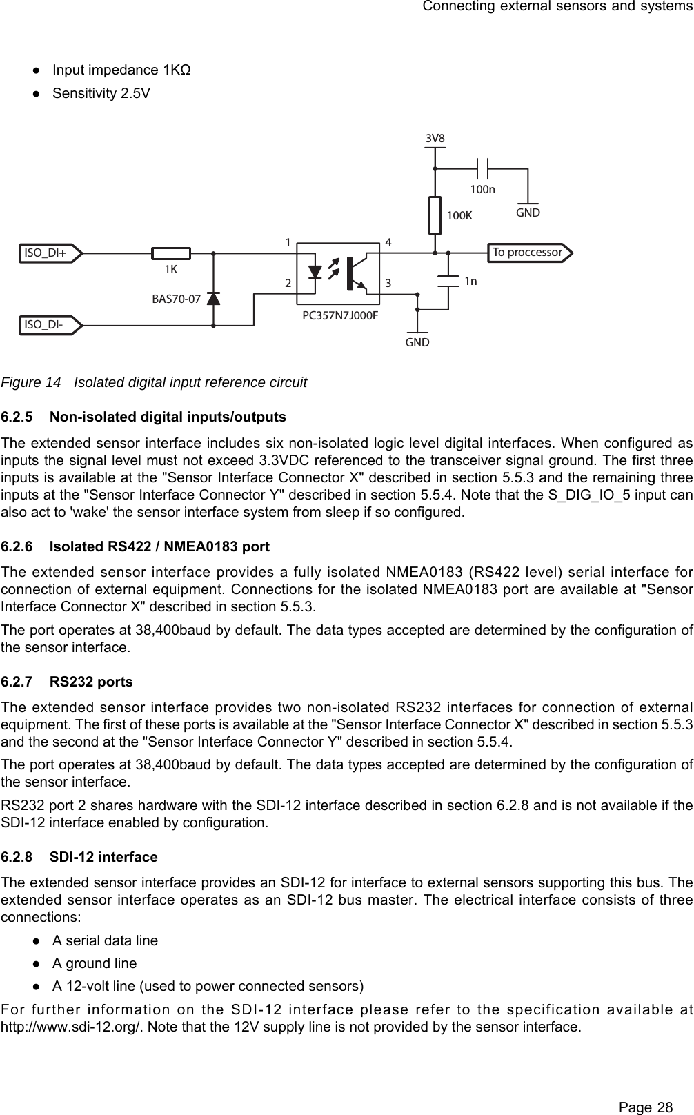
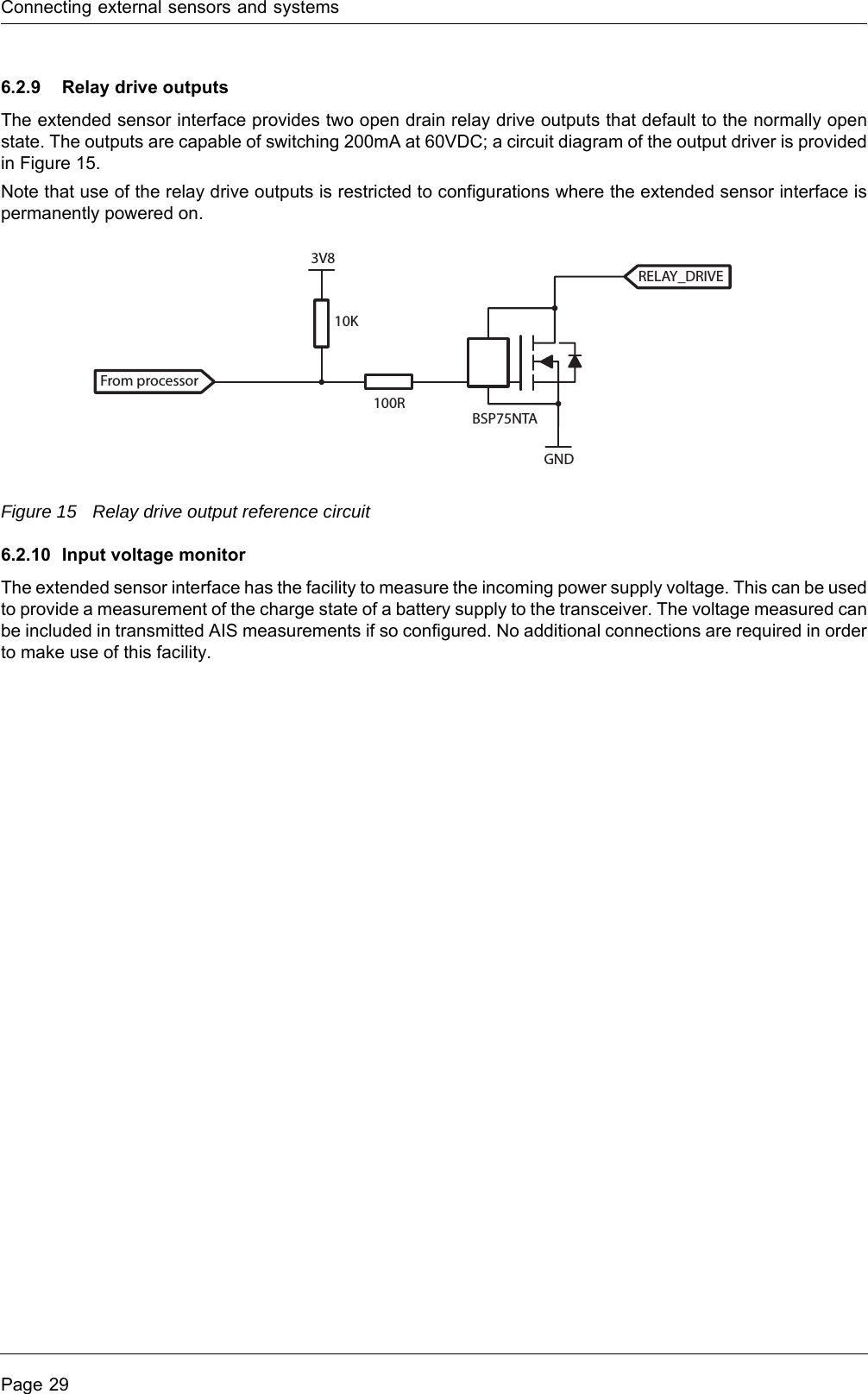
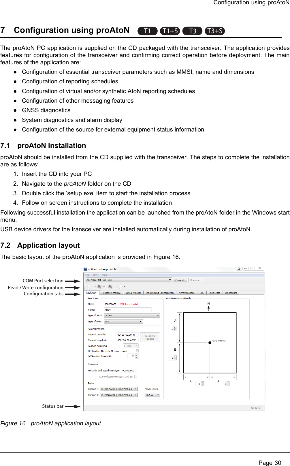
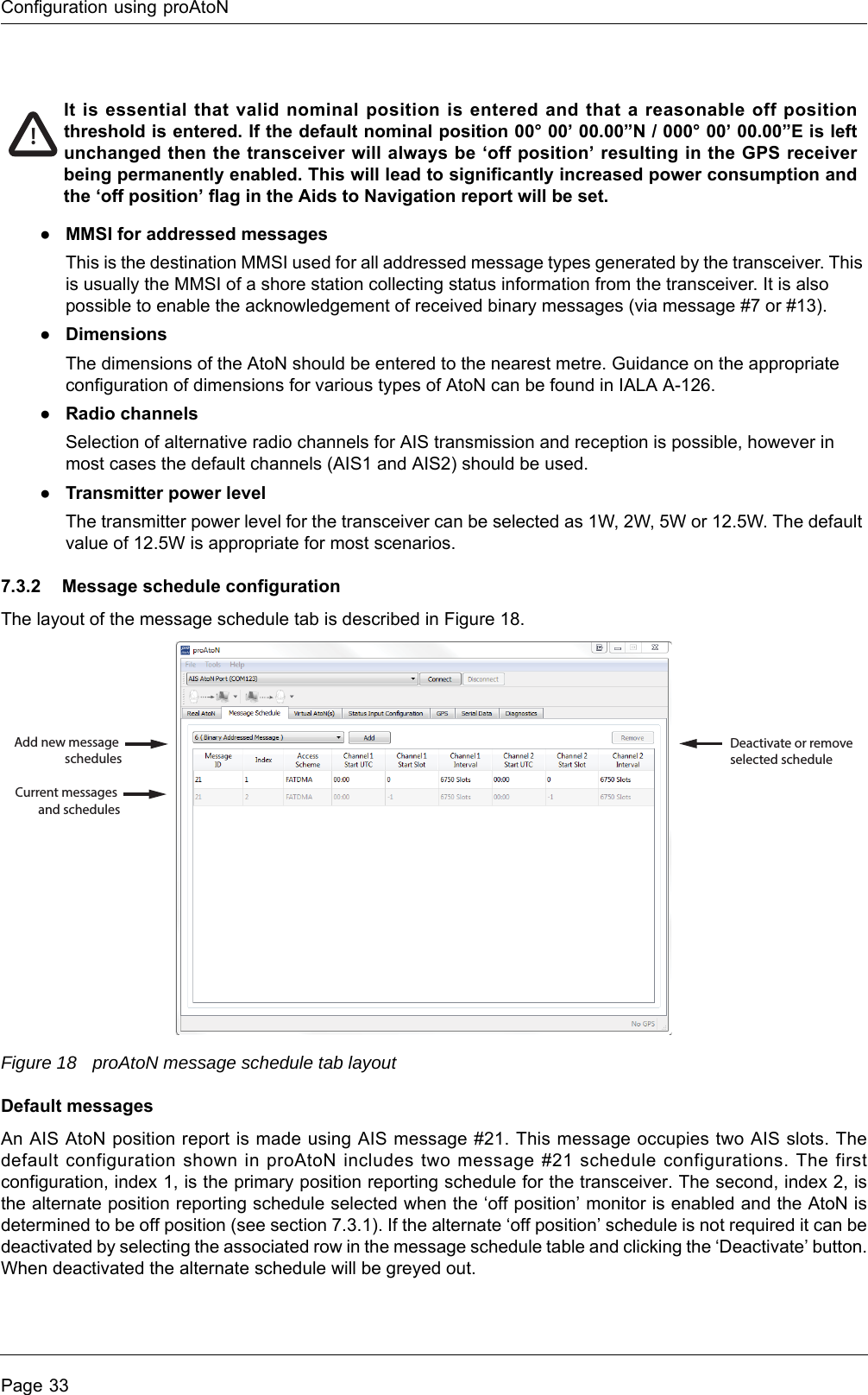
User manual - Section 1

Carbon AIS Aids to Navigation TransceiverInstallation and operation manual
 Page 11 Glossary............................................................................................... 42 Notices ................................................................................................. 52.1 Safety warnings ................................................................................................................................. 52.2 General notices.................................................................................................................................. 52.3 Regulatory information....................................................................................................................... 53 Introduction ......................................................................................... 73.1 About AIS........................................................................................................................................... 73.2 System overview................................................................................................................................ 83.3 Supported AIS messages .................................................................................................................. 94 AIS AtoN product variants ............................................................... 115 Installation ........................................................................................ 125.1 What’s in the box ............................................................................................................................. 135.2 Preparing for installation .................................................................................................................. 145.3 Attaching the bird deterrent  ............................................................................................................ 145.4 Mounting the transceiver ................................................................................................................. 155.5 Transceiver connections.................................................................................................................. 175.6 Connecting power............................................................................................................................ 225.7 Installing and connecting the VHF antenna  .................................................................................... 235.8 Installing and connecting an external GNSS antenna ..................................................................... 246 Connecting external sensors and systems.................................... 256.1 Basic transceiver interfacing............................................................................................................ 256.2 Advanced transceiver interfacing..................................................................................................... 267 Configuration using proAtoN .......................................................... 307.1 proAtoN Installation ......................................................................................................................... 307.2 Application layout............................................................................................................................. 307.3 Transceiver configuration ................................................................................................................ 327.4 Transceiver diagnostics ................................................................................................................... 407.5 Other features.................................................................................................................................. 438 Operation ........................................................................................... 448.1 Standby operation............................................................................................................................ 449 Data messages and data sources ................................................... 459.1 Product variants without the extended sensor interface .................................................................. 459.2 Variants with the extended sensor interface.................................................................................... 4610 Manual configuration........................................................................ 5010.1 Basic Type 1 AIS AtoN configuration (FATDMA operation) ............................................................ 5010.2 NMEA0183 / IEC61162 configuration sentences ............................................................................ 5010.3 Proprietary configuration sentences ................................................................................................ 5711 Technical specification .................................................................... 5911.1 Applicable equipment standards...................................................................................................... 59Table of contents
 Page 211.2 AIS Transceiver specification .......................................................................................................... 5911.3 Configuration interface specification................................................................................................ 6211.4 Drawings and dimensions................................................................................................................ 6312 Firmware upgrade procedure .......................................................... 66
 Page 3Figure 1 The AIS network ........................................................................................................................... 7Figure 2 Typical AIS AtoN system .............................................................................................................. 8Figure 3 Typical AIS AtoN system connections ........................................................................................ 12Figure 4 What’s in the box - typical configuration ..................................................................................... 13Figure 5 Attaching the bird deterrent ........................................................................................................ 14Figure 6 Using the mounting bracket........................................................................................................ 15Figure 7 Mounting to a metal plate ........................................................................................................... 16Figure 8 Removing the connector cover................................................................................................... 17Figure 9 Transceiver connector locations................................................................................................. 18Figure 10 Cable routing .............................................................................................................................. 18Figure 11 Connecting power....................................................................................................................... 22Figure 12 VHF antenna connection ............................................................................................................ 23Figure 13 Internal GPS antenna location.................................................................................................... 24Figure 14 Isolated digital input reference circuit ......................................................................................... 28Figure 15 Relay drive output reference circuit ............................................................................................ 29Figure 16 proAtoN application layout.......................................................................................................... 30Figure 17 proAtoN tab synchronisation icons ............................................................................................. 31Figure 18 proAtoN message schedule tab layout....................................................................................... 33Figure 19 Example FATDMA schedule....................................................................................................... 35Figure 20 Example RATDMA schedule ...................................................................................................... 36Figure 21 Virtual AtoN configuration tab layout .......................................................................................... 37Figure 22 Alert messages configuration tab layout..................................................................................... 38Figure 23 Status input configuration tab layout........................................................................................... 40Figure 24 Transceiver mounting bracket dimensions ................................................................................. 63Figure 25 Transceiver general assembly.................................................................................................... 64Figure 26 Transceiver dimensions.............................................................................................................. 65Figure 27 vxsend utility screenshot............................................................................................................. 66List of figures
Glossary Page 41 GlossaryAIS Automatic Identification SystemAtoN Aid to NavigationBIIT Built In Integrity TestFATDMA Fixed Access Time Division Multiple AccessGLONASS Global Navigation Satellite System (term specific to the satellite navigation system operated by the Russian Federation)GNSS Global Navigation Satellite system (general term used to refer to any satellite navigation system)GPS Global Positioning SystemIALA International Association of Lighthouse AuthoritiesIEC International Electrotechnical commissionITU International Telecommunication UnionMID (in the context of MMSI) Maritime Identification DigitsMMSI Maritime Mobile Service IdentityNMEA National Marine Electronics AssociationRACON A radar transponder used to mark navigational hazards.RATMDA Random Access Time Division Multiple AccessRS232 Serial data communications standard - see TIA-232-FRS422 Serial data communications standard see TIA-422-BSART Search And Rescue TransponderSDI-12 Serial Data Interface at 1200 BaudUSB Universal Serial BusUTC Coordinated Universal TimeVDL VHF Data LinkVHF Very High FrequencyVSWR Voltage Standing Wave Ratio
NoticesPage 52NoticesWhen reading this manual please pay particular attention to warnings marked with the warning triangle symbol shown on the left. These are important messages for safety, installation and usage of the transceiver.2.1 Safety warnings2.2 General notices2.2.1 Position sourceAll marine Automatic Identification System (AIS) transceivers utilise a satellite based location system such as the Global Positioning Satellite (GPS) network. The general term for satellite based location systems is Global Navigation Satellite System or GNSS. This manual refers to either GNSS or GPS depending on context.2.2.2 Product categoryThis product is categorised as 'exposed' in accordance with the definitions provided in IEC 60945.2.2.3 Disposal of the product and packagingPlease dispose of this product in accordance with the European WEEE Directive or with the applicable local regulations for disposal of electrical equipment. Every effort has been made to ensure the packaging for the product is recyclable. Please dispose of the packaging in an environmentally friendly manner.2.2.4 Accuracy of this manualThis manual is intended as a guide to the installation, setup and use of this product. Every effort has been made to ensure the accuracy of this manual, however due to continuous product development this manual may not be accurate in all respects, therefore no guarantee is offered. If you are in any doubt about any aspect of this product, please contact your supplier.The part number and revision number of this manual are shown on the rear cover.2.3 Regulatory information2.3.1 Declaration of conformity - R&TTEThe manufacturer of this product declares that this product is in compliance with the essential requirements and other provisions of the R&TTE directive. The declaration of conformity is provided with the product document pack. The product carries the CE mark, notified body number and alert symbol as required by the R&TTE directive. The product is intended for sale in the following member states: Great Britain, France, Spain, Sweden, Austria, Netherlands, Portugal, Denmark, Norway, Belgium, Italy, Finland, Ireland, Luxembourg, Germany and Czech Republic. !This equipment must be installed in accordance with the instructions provided in this manual. Failure to do so will seriously affect its performance and reliability. It is strongly recommended that a trained technician installs and configures this product.This equipment is intended as an aid to navigation and is not a replacement for proper navigational judgement. Information provided by the equipment must not be relied upon as accurate. User decisions based upon information provided by the equipment are done so entirely at the users own risk.!!!The accuracy of a GNSS position fix is variable and affected by factors such as the antenna positioning, how many satellites are used to determine a position and for how long satellite information has been received.
Notices Page 62.3.2 FCC noticeThis equipment has been tested and found to comply with the limits for a class B digital device, pursuant to part 15 of the FCC Rules. These limits are designed to provide reasonable protection against harmful interference in a residential installation. This equipment generates, uses and can radiate radio frequency energy and, if not installed and used in accordance with the instructions, may cause harmful interference to radio communications. This device complies with part 15 of the FCC Rules. Operation is subject to the following two conditions: (1) This device may not cause harmful interference, and (2) this device must accept any interference received, including interference that may cause undesired operation. Changes or modifications not expressly approved by the party responsible for compliance could void the user's authority to operate the equipment.2.3.3 Industry Canada noticeThis device complies with Industry Canada licence-exempt RSS standard(s). Operation is subject to the following two conditions: 1. This device may not cause interference, and 2. This device must accept any interference, including interference that may cause undesired operation of the device.This Class B digital apparatus complies with Canadian ICES-003.Le présent appareil est conforme aux CNR d'Industrie Canada applicables aux appareils radio exempts de licence. L'exploitation est autorisée aux deux conditions suivantes : 1. L'appareil ne doit pas produire de brouillage, et 2. L'utilisateur de l'appareil doit accepter tout brouillage radioélectrique subi, même si le brouillage est susceptible d'en compromettre le Fonctionnement.Cet appareil numérique de la classe B est conforme à la norme NMB-003 du Canada.
IntroductionPage 73Introduction3.1 About AISThe marine Automatic Identification System (AIS) is a location and vessel information reporting system. It allows vessels equipped with AIS to automatically and dynamically share and regularly update their position, speed, course and other information such as vessel identity with similarly equipped vessels. Position is derived from GPS or GLONASS and communication between vessels is by Very High Frequency (VHF) digital transmissions. There are a number of types of AIS device as follows:●Class A transceivers. These are designed to be fitted to commercial vessels such as cargo ships and large passenger vessels. Class A transceivers transmit at a higher VHF signal power than class B transceivers and therefore can be received by more distant vessels, they also transmit more frequently. Class A transceivers are mandatory on all vessels over 300 gross tonnes on international voyages and certain types of passenger vessels under the SOLAS mandate.   ●Inland AIS stations. Similar to class A transceivers with additional features for use on Inland waterways. ●Class B transceivers. Similar to Class A transceivers in many ways, but are normally lower cost due to the less stringent performance requirements. Class B transceivers transmit at a lower power and at a lower reporting rate than Class A transceivers. ●AIS base stations. AIS base stations are used by Vessel Traffic Systems to monitor and control the transmissions of AIS transceivers. ●Aids to Navigation (AtoN) transceivers. AtoNs are transceivers mounted on buoys or other hazards to shipping which transmit details of their location to the surrounding vessels. ●AIS receivers. AIS receivers receive transmissions from Class A transceivers, Class B transceivers, AtoNs and AIS base stations but do not transmit any information about the vessel on which they are installed. This product is an AIS Aids to Navigation (AtoN) transceiver.Figure 1 The AIS network
Introduction Page 83.2 System overviewThis AIS AtoN is a self contained device supporting both Type 1 (transmit only) and Type 3 (transmit and receive) operation. It is designed for installation in exposed locations on physical AtoN structures. The AIS AtoN can be supplied with an optional sensor interface platform which interfaces to sensors (such as weather instruments) and transmits measured data via AIS messages to surrounding vessels and shore stations.The AIS AtoN has an exceptionally low power consumption making it suitable for installation on floating Aids to Navigation with solar charged power systems. The lowest power consumption is achieved when operating as a Type 1 AIS AtoN transmitting only position information. Further description of Type 1 and Type 3 operation is provided below.Figure 2 Typical AIS AtoN system3.2.1 Type 1 AIS AtoNA Type 1 AIS AtoN is a transmit only device using the FATDMA (Fixed Access Time Division Multiple Access) access scheme. This requires that the AIS AtoN is configured with fixed AIS time slots in which it will transmit AIS messages. Mobile AIS stations operating in the area where a Type 1 AIS AtoN is installed need to be aware of the time slots allocated to the AIS AtoN. The slots allocated to the AIS AtoN are 'reserved' by AIS Base Station transmissions covering the area in which the AIS AtoN is installed. This mode of operation therefore requires that an AIS base station is operating in the same area as the AIS AtoN and is configured to make the necessary slot reservations.3.2.2 Type 3 AIS AtoNA Type 3 AIS AtoN has transmit and receive capability and can therefore use either the FATDMA or RATDMA (Random Access Time Division Multiple Access) access schemes. The RATDMA scheme allows the AIS AtoN to internally allocate slots for transmission of AIS messages without reservation from an AIS Base Station.AIS receive capability also allows a Type 3 AIS AtoN to be configured and queried for status via AIS messages sent from a shore station (known as VDL configuration). An extension of VDL configuration is 'Chaining' where configuration and query commands are passed along a 'chain' of AIS AtoN stations to a distant station beyond the range of direct communication with a shore station.3.2.3 GNSS systemsThe AIS AtoN includes an internal GNSS receiver supporting the GPS system as standard.
IntroductionPage 93.3 Supported AIS messagesThe transceiver supports the following AIS message types.ITU-R M.1371-4 Message numberDescriptionTransmitted / Received by AtoN TransceiverApplication6 Binary addressed message Transmitted and receivedThe transceiver uses message 6 to send binary data (relating to connected sensors and systems) to a specific shore station. The transceiver can also receive addressed binary messages for the purpose of configuration and control.7 Binary acknowledge message Transmitted and receivedThis message is transmitted to acknowledge receipt of a binary message. The transceiver can also receiver acknowledgements relating to its own addressed binary transmissions.8 Binary broadcast message TransmittedThe transceiver uses message 8 to broadcast binary data (relating to connected sensors and systems) to all other AIS stations in range.12 Addressed safety related message TransmittedThe transceiver can be configured to transmit an addressed safety related message to a specific shore station to alert the operator to an off position, vessel proximity or built in test failure condition.13Acknowledgement of received addressed safety related messageReceivedThe transceiver receives message 13 in acknowledgement of its transmission of message 12.14 Safety related broadcast message TransmittedThe transceiver can be configured to transmit a broadcast safety related message to all AIS stations in range to warn of an off position, vessel proximity or built in test failure condition.17 DGNSS broadcast binary message ReceivedThe transceiver can receive and process DGNSS corrections provided from a shore station using message #17. The content of these messages can be used to improve the accuracy of the on board GPS receiver.
Introduction Page 1020 Data link management message ReceivedWhen operating as a Type 3 transceiver slot reservations made by a shore station using message 20 will be observed by the transceiver.21 Aids to Navigation report TransmittedThis is the primary message transmitted by the transceiver. It contains the position, identification and status of the transceiver.25 Single slot binary message Transmitted and receivedThis message can be used for remote (over the air) configuration of the transceiver and configuration of a ‘chain’ of transceivers.ITU-R M.1371-4 Message numberDescriptionTransmitted / Received by AtoN TransceiverApplication
AIS AtoN product variantsPage 114 AIS AtoN product variantsThe transceiver is available in four variants with different AIS functionality and facilities for connection of external equipment. This manual describes features and functions for all possible product configurations. The configuration of the AIS AtoN as Type 1 or Type 3 is selected when ordering the device. The possible configurations are listed below. ●Type 1 without sensor interfaces ●Type 1 with sensor interfaces ●Type 3 without sensor interfaces●Type 3 with sensor interfaces!A system of icons is used throughout this manual to highlight which AIS AtoN configurations a particular section, paragraph or illustration applies to. Sections without any icons apply to all configurations.T1T1+ST3T3+S
Installation Page 125 Installation The AIS AtoN transceiver has been designed for ease of installation. The transceiver is self contained requiring only an external VHF antenna and power source for a basic installation. A typical system and connection diagram is provided in Figure 3.Figure 3 Typical AIS AtoN system connectionsThe main installation and commissioning steps are:1. Mount the transceiver in a suitable location on the physical Aid to Navigation2. Install a VHF antenna according to the manufacturers instructions3. Connect any sensor interfaces and lamp / RACON monitoring signals4. Connect power to the transceiver5. Configure and commission the transceiver via USB (note that this step can be carried out on shore prior to installation in a remote location)T1 T1+ST3T3+SVHF antennaLantern (optional)12/24V DC supplyGPS antenna (optional)Meteorological sensors(optional)Other sensors andmonitoring equipment(optional)AIS AtoN
InstallationPage 135.1 What’s in the boxFigure 4 shows the typical items included with the AIS AtoN transceiver. Note that the box contents vary with the specific product configuration. The following section gives a brief overview of each item. Please ensure all items are present and if any are missing please contact your supplier.Figure 4 What’s in the box - typical configuration●AIS AtoN transceiverThe main transceiver (incorporating internal GPS antenna).●Bird deterrent spikesCan be affixed to the top of the transceiver if required.●Mounting bracket and fixingsStainless steel bracket for mounting the transceiver to the physical AtoN structure.●Power and interface cableA 2m (6.6ft) long cable to supply power to the transceiver. This cable also carries some data interfaces and status signals for connection to external equipment. Depending on the supplied configuration a connector shell may be provided in place of the assembled cable.●USB configuration cableA 2m (6.6ft) long USB cable for connection to a PC when configuring the transceiver.●Sensor interface cables 2m (6.6ft) long cables for interfacing the transceiver to external sensors and systems. These cables are optional items and supplied only with transceiver configurations that include a sensor interface. Depending on the supplied configuration a connector shell may be provided in place of the assembled cable.●User manualThis document.●Support tools CDCD containing transceiver PC configuration and diagnostic tools. Product manualAIS AtoN TransceiverPower and data cableBird deterant componentsProduct CDorT1+ST3+S
Installation Page 145.2 Preparing for installationIn addition to the items provided with the transceiver the following items will be required to complete the installation.5.2.1 Tools and wiring accessoriesThe following tools and wiring accessories are required for installation:●A PoziDriv® screwdriver for assembly of the bird deterrent.●A 5mm hex key for assembly of the enclosure to the mounting bracket, and assembly of the connector cover.●A 10mm spanner for installation of the mounting bracket u-bolts.●Suitable power supply cable (0.75mm2 conductor cross section for power supply connections).●5A rated fuse or breaker appropriate to the electrical installation.●Zip ties to secure cables during installation.●Self amalgamating tape to seal any coaxial cable joints.5.2.2 VHF antenna and cableConnection of a suitable VHF antenna will be required for the AIS AtoN transceiver to operate. A robust marine band VHF antenna suited to the environment in which the AtoN will operate should be selected. The antenna cable should be terminated with a male N type connector. Any joins in the antenna cable should be made with co-axial connectors and sealed appropriately. It is recommended that RG-213 cable (or equivalent) is used to connect the VHF antenna.5.3 Attaching the bird deterrent The bird deterrent spikes are attached to the top of the transceiver using the fixing cap and screw provided. The bird deterrent is optional and if not required the fixing cap can be attached without the spikes.Figure 5 Attaching the bird deterrentT1 T1+ST3T3+ST1 T1+ST3T3+S
InstallationPage 155.4 Mounting the transceiverThe transceiver can be mounted to a physical aid to navigation using either the supplied mounting bracket or directly to a metal plate with appropriate cut outs. The installation location should provide a clear sky view to the internal GPS antenna which is located beneath the bird deterrent fixing point. Consideration should also be given to cable routing when selecting an installation location.Overall dimensions for the transceiver are provided in Figure 26. 5.4.1 Using the mounting bracketThe supplied mounting bracket can be used to install the transceiver to a vertical or horizontal pole with diameter between 1 inch and 2 inches using the supplied 'U' bolts, or to a flat surface using standard bolts (not supplied). The fixing holes in the supplied bracket are also compatible with Stauff® pipe clamps (standard series, Group 7). A detailed drawing of the mounting bracket can be found in Figure 24.The transceiver is attached to the mounting bracket using the four M4 nuts and bolts supplied.Figure 6 Using the mounting bracketT1 T1+ST3T3+S
Installation Page 165.4.2 Mounting to a metal plateThe transceiver can be mounted directly to a metal plate with a 150mm diameter cut out and fixing points located to match the details for the mounting bracket provided in Figure 24.The transceiver should be secured to the plate using four M4 fixing bolts. Figure 7 Mounting to a metal plate
InstallationPage 175.5 Transceiver connectionsThe transceiver connections are protected by the connector cover. To access the connections first remove the cover as illustrated in Figure 8.The function of each connector is identified in Figure 9 Note that the sensor interface connectors X and Y are only functional in product configurations including sensor interfacing. The function and pin allocation for each connector is described in the following sections.Figure 8 Removing the connector coverT1 T1+ST3T3+S!Note that all connecting cables must be routed through the connector cover during installation. The supplied sealing caps must be fitted to any unused connections.213
Installation Page 18Figure 9 Transceiver connector locationsThe transceiver incorporates cable routing and retention features in a screw fit component beneath the connectors. Cables should be routed through the channels provided as illustrated in Figure 10.Figure 10 Cable routingVHF antennaSensor interface connector XSensor interface connector YGround studPower and transceiverdata connector (W)External GPS antenna
InstallationPage 195.5.1 Power and transceiver interface connectorThis connector provides power to the transceiver along with interface connections for basic transceiver connectivity. The connector is a Souriau UTS714D19PW32 with type W keying and the mating half is UTS6JC14E19SW. This connector is IP68 rated when mated or unmated. * Only available when configuration includes a sensor interface, otherwise these pins are not connected.** Use only under direction of your supplierThe transceiver may be supplied with an optional pre-wired power and transceiver interface cable. Please refer to the cable drawing supplied with the transceiver to identify the individual wire colours relating to the signals described above.Pin ID Signal name Function & NotesA VIN- Transceiver power input return / 0V connectionB USER_PWR 3.3V DC output to supply interface circuits. Maximum output current 200mA.C VIN+ Transceiver power input connection (10 to 32VDC)D NMEA0183_TX1_A Transceiver NMEA0183 port 1 TX A+ signalE NMEA0183_TX1_B Transceiver NMEA0183 port 1 TX B- signalF NMEA0183_RX1_B Transceiver NMEA0183 port 1 RX B- signalG NMEA0183_RX1_A Transceiver NMEA0183 port 1 RX A+ signalH NMEA0183_RX2_A Transceiver NMEA0183 port 2 RX A+ signalJ NMEA0183_RX2_B Transceiver NMEA0183 port 2 RX B- signalK USER_IO_0 Transceiver user IO signal 0 (Light on/off input)L USER_IO_1 Transceiver user IO signal 1 (Light health input)M USER_IO_2 Transceiver user IO signal 2 (Racon health input)N GND Signal groundP RELAY_DR_1 Relay drive output 1*R RELAY_DR_2 Relay drive output 2* S GND Signal groundT USER_IO_3 Transceiver user IO signal 3U USER_IO_4 Transceiver user IO signal 4V USER_WKUP External wakeup input**T1 T1+ST3T3+S!Power connections should be kept as short as possible in order to minimise voltage drop. The cable used to connect power to the connector pins A and C should have conductors with a cross sectional area of 0.75mm2.
Installation Page 205.5.2 USB connectorThe USB connector provides USB interfaces for configuration of the transceiver and sensor interface (if provided). Only the supplied USB interface cable should be used to connect the transceiver to a PC during configuration. For further information on configuration of the transceiver and sensor interfaces refer to section 7. The USB connector should be left disconnected in the final installation and protected with the blanking cap supplied.5.5.3 Sensor interface connector X This connector provides a range of sensor interface connections. The connector is a Souriau UTS714D19PW32 with type X keying and the mating half is UTS6JC14E19SX. This connector is IP68 rated when mated or unmated. The transceiver may be supplied with an optional pre-wired sensor interface cable. Please refer to the cable drawing supplied with the transceiver to identify the individual wire colours relating to the signals described above.Pin allocation Signal name Function & NotesA ISENSE- Lamp current sense loop return (max 5A)B ISENSE+ Lamp current sense loop input (max 5A)C AN_1+ Non-isolated analogue input 1 positive connectionD S_RS422_TX1_A Sensor interface RS422 port TX A+ signalE S_RS422_TX1_B Sensor interface RS422 port TX B- signalF S_RS422_RX1_A Sensor interface RS422 port RX A+ signalG S_RS422_RX1_B Sensor interface RS422 port RX B- signalH S_RS232_TX1 Sensor interface RS232 port 1 TXJ S_RS232_RX1 Sensor interface RS232 port 1 RXK ISO_DI1+ Isolated digital input 1 positiveL ISO_DI1- Isolated digital input 1 negativeM ISO_DI2+ Isolated digital input 2 positiveN ISO_DI2- Isolated digital input 2 negativeP AN_1- Non-isolated analogue input 1 negative connectionR S_DIG_IO_1 Non-isolated digital IO 1S S_RS422_GND Senor interface RS422 port groundT GND Signal groundU S_DIG_IO_3 Non-isolated digital IO 3V S_DIG_IO_2 Non-isolated digital IO 2T1 T1+ST3T3+ST1+ST3+S
InstallationPage 215.5.4 Sensor interface connector YThis connector provides a range of sensor interface connections. The connector is a Souriau UTS714D19PW32 with type Y keying and the mating half is UTS6JC14E19SY . This connector is IP68 rated when mated or unmated. The transceiver may be supplied with an optional pre-wired sensor interface cable. Please refer to the cable drawing supplied with the transceiver to identify the individual wire colours relating to the signals described above.5.5.5 VHF antenna connector The VHF antenna connector is a female 'N' type co-axial connector. The antenna ground is galvanically isolated from the AIS AtoN system ground. The connector and mating half must be sealed with self amalgamating tape once mated. A lighting protector should be installed in line with the VHF antenna connector. The recommended lighting protector is Huber+Suhner part number 3401.17.C with gas discharge tube 9071.99.0547.5.5.6 External GNSS antenna connector The external GNSS antenna connector is a female 'TNC' co-axial connector. An external GNSS antenna can be connected here if the installation prohibits use of the internal GPS antenna. The connector and mating half must be sealed with self amalgamating tape once mated.Pin allocation Signal name Function & NotesA S_RS232_TX2 Sensor interface RS232 port 2 TXB S_RS232_RX2 Sensor interface RS232 port 2 RXC S_DIG_IO_4 Non-isolated digital IO 4D EXT_WAKEUP External wake up input E SDI_DATA SDI Bus data signalF ISO_DI_3+ Isolated digital input 3 positiveG ISO_DI_3- Isolated digital input 3 negativeH ISO_DI_4+ Isolated digital input 4 positiveJ ISO_DI_4- Isolated digital input 4 negativeK ISO_DI_5+ Isolated digital input 5 positiveL ISO_DI_5- Isolated digital input 5 negativeM ISO_AN_1+ Isolated analogue input 1 positiveN ISO_AN_1- Isolated analogue input 1 negativeP ISO_AN_2+ Isolated analogue input 2 positiveR ISO_AN_2- Isolated analogue input 2 negativeS AN_2+ Non-isolated analogue input 2 positive connectionT AN_2- Non-isolated analogue input 2 negative connectionU AN_3+ Non-isolated analogue input 3 positive connectionV AN_3- Non-isolated analogue input 3 negative connectionT1+ST3+S
Installation Page 22Refer to section 5.8 for further detail on the selection and installation of an external GNSS antenna. If the External GNSS antenna connector is not used it must be protected with the supplied blanking cap.5.5.7 Earth connection stud The earth connection stud is an M4 stud connected to the VHF antenna ground. This point should be connected to a common grounding point for lighting protection. Note that the ground stud is galvanically isolated from the incoming transceiver and power supply.5.6 Connecting powerThe transceiver requires a nominal 12VDC or 24VDC supply and will operate between 10V and 32VDC. The peak current drawn when operating from 12VDC is 3A and when operating from 24VDC is 2.5A. Power should be connected using either the supplied moulded interface connector and cable, or the appropriate Souriau connector mating half. It is recommended that 5A rated fuses are installed in line with the power supply positive and negative connections.Figure 11 Connecting powerOverall power consumption is dependent on the configuration of the transceiver messaging and sensor interface. Minimum power consumption figures are provided in section 11.T1 T1+ST3T3+SRedBlackPower supply +Power supply –
InstallationPage 235.7 Installing and connecting the VHF antenna The VHF antenna should have the following specification:●Centre frequency 159MHz●VSWR < 2.0●Impedance 50 Ohms●Power handling 12.5 Watts●Gain 3dBi or 6dBiIt is recommended that high quality RG213 or RG214 co-axial cable is used to connect the VHF antenna to the transceiver. The antenna cable should be as short as possible and no more than 30 metres (100 feet) in length.When selecting the installation location for the VHF antenna:●Install the antenna as high as possible on the physical aid to navigation●Keep the antenna away from any large vertical metallic structures.●Install the antenna as far away as possible from any other VHF antennasFigure 12 VHF antenna connectionT1 T1+ST3T3+S!The performance and reliability of the VHF antenna is essential to correct operation of the transceiver. Ensure that a high quality antenna suitable for use in harsh environmental conditions is selected. Ensure all co-axial connections are well made and watertight.!The VHF antenna should be installed according to the manufacturer's instructions.VHF antennaGPS antenna (optional)AIS AtoN
Installation Page 245.8 Installing and connecting an external GNSS antennaThe transceiver has an internal GPS antenna that is suitable for most applications and installation locations. The location of the internal GPS antenna is shown in Figure 13.Figure 13 Internal GPS antenna locationIf the installation requires an external GNSS antenna it should be specified as follows:●Centre frequency 1575.42MHz for GPS operation. ●Active antenna with overall gain of at least 20dB●Bias voltage 3.3V●Impedance 50 Ohms●VSWR <2.0When installing the transceiver (using the internal GPS antenna) or an external GNSS antenna:●Make sure the antenna has a clear view of the sky with no overhead obstructions●Position the antenna as far as possible from any VHF or other transmitting antennas●Position the antenna as high as possible on the physical aid to navigation.It is recommended that high quality RG213 or RG214 co-axial cable is used to connect the GNSS antenna to the transceiver. The antenna cable should be as short as possible and no more than 10 metres (30 feet) in length.T1 T1+ST3T3+S!The performance and reliability of the GNSS antenna is essential to correct operation of the transceiver. Ensure that a high quality antenna suitable for use in harsh environmental conditions is selected. Ensure all co-axial connections are well made and watertight.!The GNSS antenna should be installed according to the manufacturer's instructions.Internal GPS antenna location
Connecting external sensors and systemsPage 256 Connecting external sensors and systemsThe transceiver can be interfaced to external sensors and systems for the transmission of sensor data via the AIS network. Typically metrological and hydrological sensors are interfaced to the transceiver so that local conditions can be shared with other AIS users.The transceiver is available with and without extended sensor interfaces as described in section 4. Section 6.1 describes the interfaces available without the extended sensor interface while section 6.2 describes the interfaces available with the extended sensor interface.6.1 Basic transceiver interfacingThis section describes the interfaces available without the extended sensor interface. In this version of the transceiver only the power and transceiver interface connector is used for connection of external equipment. The interfaces available are:●Five user configurable input/output signals●A bi-directional NMEA0183 port●An input only NMEA0183 portThe transceiver also has the ability to measure the incoming power supply voltage. This measurement is used by the transceivers BIIT (Built In Integrity Test) routines and can be used to trigger changes to the transceiver health flag in AIS message #21 (the AtoN position report) or additional AIS alert messages if so configured.6.1.1 Basic user configurable input / output signalsThe basic user I/O signals are 3.3V logic level signals and configurable as inputs or outputs. These connections can be configured as inputs and mapped to the AtoN status bits in AIS message #21 (the AtoN position report). The default mapping of the signals is described in the table below and these connections are available at the 'Power and transceiver interface connector' described in section 5.5.1.Configuration of the source and other settings for AtoN status information is described in section 6.1.3.6.1.2 Basic Lamp and RACON status interfacingAdditional circuitry may be required to interface the lamp or RACON status outputs to the transceiver. Please contact your supplier with details of the lamp or RACON for further information. The encoding of the connected equipment status to the lamp and RACON status is defined below.●Light on / off - User IO 0 (logic high input = light on)●Light health - User IO 1 (logic high input = light error)●Racon health - User IO 2 (logic high input = RACON operational)When appropriately configured the status of the lamp and RACON signals will be sampled prior to each AtoN position report transmission and the status encoded in the message.6.1.3 AtoN Status source and configurationAIS AtoN position report messages (AIS message #21) contain status bits describing the status of a connected lamp and RACON. The general health of the transceiver is also provided as either ‘good health’ or alarm. The transceiver can be configured to obtain status information from one of three sources:●Directly from the transceiver basic I/O signals described in 6.1.1●From the extended sensor interface isolated digital inputs described in 6.2.4●By input of an ACE (Extended General AtoN Station configuration command) sentence to one of the transceiver NMEA0183 port. The ACE sentence is described in section 10.2.2. This sentence can be used to supply the status bits for transmission rather than sourcing from the hardware inputs.T1 T1+ST3T3+S!Voltages above 3.3V must not be connected to these inputs. An external circuit and isolation may be required to interface external equipment. Isolated status inputs are available with the extended sensor interface and are described in section 6.2.
Connecting external sensors and systems Page 26The source of the status information is configured using either proAtoN (see section 7). The following settings must also be configured using proAtoN:●Lamp fitted / not fitted●Racon fitted / not fitted●Racon monitored / not monitoredNote that the AIS AtoN ‘health’ bit is generated internally by the transceiver. However, if the ACE sentence is configured as the source for status information then the AIS AtoN ‘health’ bit is the combination of the internal transceiver health and the ACE sentence health bit. In this configuration if either the internal transceiver health or the external health status provided by the ACE sentence is set to ‘1’ (alarm) then the status will be transmitted as alarm.6.1.4 Bi-directional NMEA0183 portThe bi-directional NMEA port (port 1) is available at the 'Power and transceiver interface connector' described in section 5.5.1. This port accepts and outputs NMEA0183/IEC61162-1 sentences for configuration of the transceiver and communication of binary message payload data (see section 7) to the transceiver for transmission in AIS messages. Whilst the transceiver is awake own position reports are also output to this port (as AIVDO messages) and in the case of a Type 3 transceiver remote vessel reports (as AIVDM messages) are also output.The electrical and interface specification for this port is as follows:●Four wire NMEA0183 / IEC61162-1/2 port (RS422 levels)●Baud rate 38,400baud●Isolated receiver circuitry, non-isolated transmitter circuitry6.1.5 Input only NMEA0183 portThe input only NMEA port (port 2) is available at the 'Power and transceiver interface connector' described in section 5.5.1. The electrical and interface specification for this port is as follows:●Two wire NMEA0183 / IEC61162-1/2 port (RS422 levels)●Baud rate 38,400baud●Isolated receiver circuitry6.2 Advanced transceiver interfacingThis section describes the interfaces available with the extended sensor interface. In this version of the transceiver all three 19 way connectors are used for connection of external equipment. The interfaces available in addition to those described in section 6.1 are:●Two fully isolated analogue inputsPort signal name FunctionNMEA0183_TX1_A Transceiver NMEA0183 port 1 TX A+ signalNMEA0183_TX1_B Transceiver NMEA0183 port 1 TX B- signalNMEA0183_RX1_B Transceiver NMEA0183 port 1 RX B- signalNMEA0183_RX1_A Transceiver NMEA0183 port 1 RX A+ signalPort signal name FunctionNMEA0183_RX2_A Transceiver NMEA0183 port 2 RX A+ signalNMEA0183_RX2_B Transceiver NMEA0183 port 2 RX B- signalT1+ST3+S
Connecting external sensors and systemsPage 27●Three non-isolated analogue inputs●A lamp current sense loop●Five isolated digital inputs●Five non-isolated digital inputs / outputs●A fully isolated RS422 / NMEA0183 port●Two RS232 ports ●An SDI-12 serial bus interface (one RS232 port is unavailable if this interface is used)●Two relay drive outputsThe following sections describe the hardware specification and interface to these inputs. The function of the sensor interface (in terms of translation of sensor data to AIS messages) is determined by the software configuration of the AIS AtoN. The default configuration and supported sensors are described in section 8 of this document. For alternate configurations please refer to the additional documentation supplied with the product or contact your supplier.6.2.1 Isolated analogue inputsThe extended sensor interface includes two isolated analogue inputs. These inputs are available at "Sensor Interface Connector Y" described in section 5.5.4. The electrical and measurement specification of these inputs is as follows: ●Differential input range ±13.75V●Impedance 22KΩ●16 bit resolutionThe voltage to be measured should be applied across the differential positive and negative inputs.6.2.2 Non-isolated analogue inputsThe extended sensor interface includes three non-isolated analogue inputs. The first of these inputs is available at the "Sensor Interface Connector X" described in section 5.5.3 and the remaining two inputs at the "Sensor Interface Connector Y" described in section 5.5.4. The electrical and measurement specification for these inputs is as follows:●Differential input range ± 37.2V●Impedance 620KΩ●12 bit resolutionThe voltage to be measured should be applied across the differential positive and negative inputs.6.2.3 Lamp current sense loopThe extended sensor interface includes a lamp current sense loop. This facility is intended for health monitoring of a lamp on the physical aid to navigation. Connections for the lamp current sense loop are available at "Sensor Interface Connector X" described in section 5.5.3. The specification of the current sense loop is as follows:●Maximum current 5A●Measurement of currents up to 0.5A●12 bit resolution6.2.4 Isolated digital inputsThe extended sensor interface includes five isolated digital inputs. These inputs are intended for use with status outputs from external equipment such as lamps, RACONs and power supply monitoring systems. The first two inputs is available at the "Sensor Interface Connector X" described in section 5.5.3 and the remaining three inputs at the "Sensor Interface Connector Y" described in section 5.5.4. The specification for these inputs is as follows:●Maximum input voltage ±15V
Connecting external sensors and systems Page 28●Input impedance 1KΩ●Sensitivity 2.5VFigure 14 Isolated digital input reference circuit6.2.5 Non-isolated digital inputs/outputsThe extended sensor interface includes six non-isolated logic level digital interfaces. When configured as inputs the signal level must not exceed 3.3VDC referenced to the transceiver signal ground. The first three inputs is available at the "Sensor Interface Connector X" described in section 5.5.3 and the remaining three inputs at the "Sensor Interface Connector Y" described in section 5.5.4. Note that the S_DIG_IO_5 input can also act to 'wake' the sensor interface system from sleep if so configured.6.2.6 Isolated RS422 / NMEA0183 portThe extended sensor interface provides a fully isolated NMEA0183 (RS422 level) serial interface for connection of external equipment. Connections for the isolated NMEA0183 port are available at "Sensor Interface Connector X" described in section 5.5.3.The port operates at 38,400baud by default. The data types accepted are determined by the configuration of the sensor interface.6.2.7 RS232 portsThe extended sensor interface provides two non-isolated RS232 interfaces for connection of external equipment. The first of these ports is available at the "Sensor Interface Connector X" described in section 5.5.3 and the second at the "Sensor Interface Connector Y" described in section 5.5.4.The port operates at 38,400baud by default. The data types accepted are determined by the configuration of the sensor interface. RS232 port 2 shares hardware with the SDI-12 interface described in section 6.2.8 and is not available if the SDI-12 interface enabled by configuration.6.2.8 SDI-12 interfaceThe extended sensor interface provides an SDI-12 for interface to external sensors supporting this bus. The extended sensor interface operates as an SDI-12 bus master. The electrical interface consists of three connections:●A serial data line●A ground line●A 12-volt line (used to power connected sensors)For further information on the SDI-12 interface please refer to the specification available at http://www.sdi-12.org/. Note that the 12V supply line is not provided by the sensor interface.ISO_DI+ To proccessor1K100K100n1n3V8GNDGND1243BAS70-07PC357N7J000FISO_DI-
Connecting external sensors and systemsPage 296.2.9 Relay drive outputsThe extended sensor interface provides two open drain relay drive outputs that default to the normally open state. The outputs are capable of switching 200mA at 60VDC; a circuit diagram of the output driver is provided in Figure 15.Note that use of the relay drive outputs is restricted to configurations where the extended sensor interface is permanently powered on.Figure 15 Relay drive output reference circuit6.2.10 Input voltage monitorThe extended sensor interface has the facility to measure the incoming power supply voltage. This can be used to provide a measurement of the charge state of a battery supply to the transceiver. The voltage measured can be included in transmitted AIS measurements if so configured. No additional connections are required in order to make use of this facility.From processorRELAY_DRIVE10K100R3V8GNDBSP75NTA
Configuration using proAtoN Page 307 Configuration using proAtoNThe proAtoN PC application is supplied on the CD packaged with the transceiver. The application provides features for configuration of the transceiver and confirming correct operation before deployment. The main features of the application are:●Configuration of essential transceiver parameters such as MMSI, name and dimensions●Configuration of reporting schedules●Configuration of virtual and/or synthetic AtoN reporting schedules●Configuration of other messaging features●GNSS diagnostics●System diagnostics and alarm display●Configuration of the source for external equipment status information7.1 proAtoN InstallationproAtoN should be installed from the CD supplied with the transceiver. The steps to complete the installation are as follows:1. Insert the CD into your PC2. Navigate to the proAtoN folder on the CD3. Double click the ‘setup.exe’ item to start the installation process4. Follow on screen instructions to complete the installationFollowing successful installation the application can be launched from the proAtoN folder in the Windows start menu. USB device drivers for the transceiver are installed automatically during installation of proAtoN. 7.2 Application layoutThe basic layout of the proAtoN application is provided in Figure 16.Figure 16 proAtoN application layoutT1 T1+ST3T3+SCOM Port selectionRead / Write congurationConguration tabsStatus bar
Configuration using proAtoNPage 31COM Port selectionWhen connected via USB the COM port associated with the transceiver will be listed in the selection drop down. To connect to the transceiver select the ‘AIS AtoN Port’ option from the drop down and click the ‘Connect’ button.Read / Write configurationClicking the left hand button will transfer current configuration information from the transceiver to proAtoN.Clicking the right hand button will configure the transceiver with the information currently displayed in proAtoN.It is possible to select transfer of configuration information relating only to the currently selected tab, or to all tabs by clicking the drop down arrow to the right of each button.Configuration tabsThe configuration and status of the transceiver is displayed through a number of tabs. ●Real AtoN tabConfiguration of AtoN MMSI, name, type and dimensions.●Message schedule tabConfiguration of FATDMA or RATDMA message schedules.●Virtual AtoN tabConfiguration of virtual and/or synthetic AtoN transmissions.●Status input configuration tabConfiguration of the source for AtoN status information●Alert messages tabConfiguration of non-periodic messages (e.g., vessel proximity alert messages).●GPSDisplays signal strength and status information for the transceiver GPS receiver.●DiagnosticsDisplays software version information, alarms and other key status information.●Serial dataDisplays raw IEC61162 (NMEA0183) data output from the transceiver.When connected to a transceiver a synchronisation status icon is displayed alongside the title of each tab. This icon indicates the current synchronisation status of the information displayed in that tab with the internal configuration of the transceiver. The synchronisation status icons are shown in Figure 17.Figure 17 proAtoN tab synchronisation iconsSynchronisation is achieved by either writing the configuration displayed in proAtoN to the transceiver (click the write configuration button), or reading the current configuration from the transceiver for display in proAtoN (click the read configuration button).Green - Tab synchronisedRed - Tab not synchronisedBlue - Synchronisation in progressTab edited (sync required)
Configuration using proAtoN Page 32Status barThe status bar displays the current connection status of the application (bottom left) and the current GPS time (if available, bottom right).7.3 Transceiver configurationThe following sections describe the configuration options available and their effect on the behavior of the transceiver. Configuration of an AIS AtoN transceiver requires knowledge of the local AIS environment and may require interaction with shore infrastructure. Familiarity with the current IALA guidelines on the use of AIS Aids to Navigation (IALA A-126) is assumed.7.3.1 Configuration of ‘Real’ AtoN parametersThe following parameters associated with the ‘real’ AIS AtoN transceiver should be configured via the ‘Real AtoN’ tab:●MMSIThe MMSI number associated with the ‘real’ AtoN. Typically the MMSI number for a ‘real’ AtoN station follows the format 99MID1XXX where MID is the appropriate national MID and XXX is a number unique to this station.●NameThe name of the AtoN station as broadcast to other AIS users. Up to 34 characters are available for the name.●Type of AtoNSelect from a list of possible types of AtoN. The types are as defined by IALA in IALA A-126.●Type of EPFSSelect the type of EPFS (Electronic Position Fixing System) used by the transceiver. The transceiver is available with either GPS or GLONASS GNSS fitted and the appropriate system should be selected here. Note this selection does not affect the hardware configuration, only the contents of the ‘Type of EPFS’ field in transmitted AtoN position reports. Alternatively for a fixed or shore based transceiver a surveyed position type can be selected. Note that when the surveyed position is selected the surveyed position is broadcast to other AIS users and GNSS position information is ignored.●Nominal positionEnter the nominal or charted position of the AtoN. This is the position transmitted to other AIS users for a fixed AtoN when the ‘Surveyed’ EPFS type is selected. For all other configurations this position is used to perform ‘off position’ calculations only; the actual GNSS position is broadcast to other users. ○The application can average the current GNSS position over 5 minutes and use this value for the nominal position. Click the ‘Get GNSS position’ button to the right of the latitude and longitude fields to begin this process.○The position accuracy can only be entered when the type of EPFS is set to ‘Surveyed’. The accuracy should be set in accordance with the accuracy of the surveyed position.●Off position alternate message enableThe current GNSS position is compared to the nominal position according to the algorithm defined in IALA A-126 Annex A, Example 1. The off position threshold distance is specified in metres. If the transceiver determines that it is ‘off position’ then the alternate reporting schedule for message #21 (index 2) is enabled. For example, the alternate reporting schedule could be configured to decrease the reporting interval if the AtoN has drifted off position. The off position flag in message #21 is set when off position regardless of this setting.The transceiver off position algorithm is always operational and compares the current GPS position to the nominal position of the transceiver.
Configuration using proAtoNPage 33●MMSI for addressed messagesThis is the destination MMSI used for all addressed message types generated by the transceiver. This is usually the MMSI of a shore station collecting status information from the transceiver. It is also possible to enable the acknowledgement of received binary messages (via message #7 or #13).●DimensionsThe dimensions of the AtoN should be entered to the nearest metre. Guidance on the appropriate configuration of dimensions for various types of AtoN can be found in IALA A-126.●Radio channelsSelection of alternative radio channels for AIS transmission and reception is possible, however in most cases the default channels (AIS1 and AIS2) should be used.●Transmitter power levelThe transmitter power level for the transceiver can be selected as 1W, 2W, 5W or 12.5W. The default value of 12.5W is appropriate for most scenarios.7.3.2 Message schedule configurationThe layout of the message schedule tab is described in Figure 18.Figure 18 proAtoN message schedule tab layoutDefault messagesAn AIS AtoN position report is made using AIS message #21. This message occupies two AIS slots. The default configuration shown in proAtoN includes two message #21 schedule configurations. The first configuration, index 1, is the primary position reporting schedule for the transceiver. The second, index 2, is the alternate position reporting schedule selected when the ‘off position’ monitor is enabled and the AtoN is determined to be off position (see section 7.3.1). If the alternate ‘off position’ schedule is not required it can be deactivated by selecting the associated row in the message schedule table and clicking the ‘Deactivate’ button. When deactivated the alternate schedule will be greyed out.!It is essential that valid nominal position is entered and that a reasonable off position threshold is entered. If the default nominal position 00° 00’ 00.00”N / 000° 00’ 00.00”E is left unchanged then the transceiver will always be ‘off position’ resulting in the GPS receiver being permanently enabled. This will lead to significantly increased power consumption and the ‘off position’ flag in the Aids to Navigation report will be set.Add new message schedulesCurrent messages and schedulesDeactivate or removeselected schedule
Configuration using proAtoN Page 34Adding additional messages to the scheduleAdditional binary data messages can be added to the schedule table by selecting the required message type from the drop down at the top of this tab, then clicking the ‘Add’ button. The available message types are:●Message #8 - for broadcast of binary data to all other stations in range. The binary data may be provided by the extended sensor interface (if present) or third party equipment connected to the transceiver. See section 8 for further information.●Message #6 - for transmission of binary data to an individual destination MMSI. The destination MMSI is set on the ‘Real AtoN’ tab. The binary data may be provided by the extended sensor interface (if present) or third party equipment connected to the transceiver. See section 8 for further information.●Message #12 - for transmission of text messages to an individual destination MMSI. The destination MMSI is set on the ‘Real AtoN’ tab. This schedule is used for transmission of alert messages (see section 7.3.6).●Message #14 - for broadcast of text messages to all other stations in range. This schedule is used for transmission of alert messages (see section 7.3.6).Up to four separate schedules are available for each binary message type. Each individual schedule has an index from 1 to 4 which is used to identify that schedule (for example, message #8 index 2). Access scheme selectionThe TMDA access scheme for each message must be selected as either FATDMA or RATDMA (see section 3.2). The selection is made by selecting the required row in the schedule table, then clicking on the current access scheme in that row. A drop down menu will then appear in that location allowing selection of the required access scheme. ●FADTMA Configuration of an FATDMA schedule continues in section 7.3.3.●RATDMA Configuration of an RATMDA schedule continues in section 7.3.4.7.3.3 FATDMA Schedule configuration Using the FATDMA (Fixed Access TDMA) access scheme the actual slot for each transmission made by the transceiver is specified.  There are 2250 slots per minute (or frame) on each AIS channel. The scheduled slots must be reserved for the transceiver by an AIS base station operating in the same area using AIS message #20. Further information on FATDMA reservations and slot allocation schemes can be found in IALA A-124, Appendix 14.The parameters required for an FATDMA schedule are as follows.Channel 1 start UTCThis is the hour and minute for transmission on channel 1. This specifies the AIS frame (minute) within a day in which the start slot for channel 1 resides. Channel 1 start slotThis is the slot number for the first transmission on channel 1. The slot number can range from -1 (transmission disabled on this channel) to 2249. Note that each message #21 transmission occupies two slots and associated base station slot reservations must therefore reserve two slots.Channel 1 intervalThis is the interval in slots between transmissions on channel 1. The interval can range from 0 to 3240000 slots, which equates to an interval of one day. Typically the interval is set to 13500 slots (6 minutes) on each channel which results in an overall interval of 3 minutes.T1 T1+ST3T3+ST3T3+ST1 T1+ST3T3+S

Navigation menu