SRT Marine Systems plc 4180013 AIS AtoN (Aids-to-Navigation) User Manual AtoN Express Front Manual Cover v1
Software Radio Technology plc AIS AtoN (Aids-to-Navigation) AtoN Express Front Manual Cover v1
User manual
SRT Marine
System Solutions
AtoN Express
AIS Aids to Navigation Transceiver
Installation and operation manual
Thank you for buying this AtoN Express.
This product has been engineered to offer you the highest level of performance
and durability and we hope that it will provide many years of reliable service.
We constantly strive to achieve the highest possible quality standards, should
you encounter any problems with this product, please contact your dealer who
will be pleased to offer whatever assistance you require.

Page 1
Contents
1 - Notices ................................................................................. 2
1.1 - Safety warnings.................................................................. 2
1.2 - General notices .................................................................. 2
2 - About AIS............................................................................. 3
2.1 - Static and dynamic vessel data.......................................... 4
3 - Installing and charging the AtoN Express........................ 5
3.1 - Supplied items.................................................................... 5
3.2 - Installing the AtoN Express bracket ................................... 7
3.3 - Fitting the AtoN Express to Bracket ................................... 8
3.4 - Charging the AtoN Express................................................ 9
3.5 - Installing the Power box................................................... 10
4 - Configuring the AtoN Express......................................... 12
4.1 - Installing proAtoN Express - PC....................................... 12
4.2 - Connecting to the AtoN Express...................................... 12
4.3 - Basic configuration........................................................... 13
4.4 - Message Schedule Configuration .................................... 14
5 - Using the AtoN Express ................................................... 16
5.1 - Activating and deactivating the AtoN Express ................. 17
5.2 - Status indicator ................................................................ 18
6 - Troubleshooting................................................................ 20
7 - Specification...................................................................... 21
List of Figures
Figure 1 - AtoN Express package contents................................ 5
Figure 2 - Installing the AtoN Express bracket .......................... 7
Figure 3 - Fitting the AtoN Express into the bracket................... 8
Figure 4 - Charging the AtoN Express....................................... 9
Figure 5 - Installing the Power Box.......................................... 11
Figure 6 - proAtoN Express configuration tab ......................... 14
Figure 7 - AtoN Express status indicator................................. 16
Figure 8 - Activating the AtoN Express.................................... 17
Figure 9 - Identified common status indications - while active 19

Notices
Page 2
1Notices
1.1 Safety warnings
1.2 General notices
Position source
All marine Automatic Identification System (AIS) transceivers utilise a satellite based location system such as the Global Positioning
System (GPS) network.
The accuracy of a GPS position fix is variable and is affected by factors such as the antenna positioning, how many satellites are used
to determine a position and for how long satellite information has been received for.
RF emissions notice
Caution: The AIS transceiver generates and radiates radio frequency electromagnetic energy. This equipment must be installed and
operated according to the instructions contained in this manual. Failure to do so can result in personal injury and / or AIS transceiver
malfunction.
Accuracy of this manual
AtoN Express may be upgraded from time to time and future versions of AtoN Express may therefore not correspond exactly with this
manual. Information contained in this manual is liable to change without notice. The manufacturer of this product disclaims any liability
for consequences arising from omissions or inaccuracies in this manual and any other documentation provided with this product.
When reading this manual please pay attention to warnings marked with the warning triangle shown on the left. These
are important messages for safety, installation and usage of the product.
!
This equipment must be installed in accordance with the instructions provided in this manual.
!
Do not install this equipment in a flammable atmosphere such as in an engine room or near to fuel tanks.
!
!
Any attempt to tamper with or damage this product will invalidate the warranty.
!
This product contains a Lithium-Ion battery. Never expose to fire or high temperatures. Do not attempt to disassemble
the product. Do not short circuit the battery or attempt to charge with equipment other than the supplied charger.

About AIS
Page 3
2 About AIS
The marine Automatic Identification System (AIS) is a location and vessel information reporting system. It allows vessels equipped with
AIS to automatically and dynamically share and regularly update their position, speed, course and other information such as vessel
identity with similarly equipped vessels. Position is derived from the Global Positioning System (GPS) and communication between
vessels is by Very High Frequency (VHF) digital transmissions.
There are a number of types of AIS device as follows:
•Class A transceivers. Are designed to be fitted to large vessels such as cargo ships and large passenger vessels. Class A
transceivers transmit at a higher VHF signal power than class B transceivers and therefore can be received by more distant vessels.
They also transmit more frequently. Class A transceivers are mandatory on all vessels over 300 gross tonnes on international
voyages and certain types of passenger vessels under SOLAS regulations.
•Class B transceivers. Similar to class A transceivers in many ways, but are normally lower cost due to the less stringent
performance requirements. Class B transceivers transmit at a lower power and at a lower reporting rate than class A transceivers.
•AIS base stations. AIS base stations are used by Vessel Traffic Systems to monitor and control the transmissions of AIS transceivers.
•Aids to Navigation (AtoN) transceivers. AtoN’s are transceivers mounted on buoys or other hazards to shipping which transmit
details of their location to the surrounding vessels.
•AIS receivers. AIS receivers will generally receive transmissions from class A transceivers, class B transceivers, AtoNs and AIS
base stations but do not transmit any information about the vessel on which they are installed.
•AIS AtoN Express. The AtoN Express is a unique, self-contained AIS Aid-to-Navigation. The key features of the AtoN Express are
as follows:
• Self-contained VHF and GPS antennas
• Internal rechargeable battery pack for up to 5 days of operation
• Simple installation

About AIS
Page 4
2.1 Static and dynamic vessel data
There are two categories of information transmitted by an AIS device: static and dynamic data.
The vessel's dynamic data, which includes location, speed over ground (SOG) and course over ground (COG), is calculated
automatically using the internal GPS receiver. Dynamic data is not transmitted by AIS AtoN’s.
Static data is information about the vessel or Aid-to-Navigation which must be programmed into the AIS device. This includes:
• Maritime Mobile Service Identity (MMSI)
• Vessel or AtoN name
• Vessel call sign (if available, not relevant to AtoN’s)
• Vessel or AtoN type
• Vessel or AtoN dimensions
In most countries the operation of an AIS AtoN device will require the local authority to grant an operating license and MMSI number.
An MMSI number is required in order for the AIS device to operate. The product requires an AtoN specific MMSI number with
the format 99*******. Please contact the relevant authority in your country for more information.
!

Installing and charging the AtoN Express
Page 5
3 Installing and charging the AtoN Express
3.1 Supplied items
Figure 1 shows the items that are included with each AtoN Express.
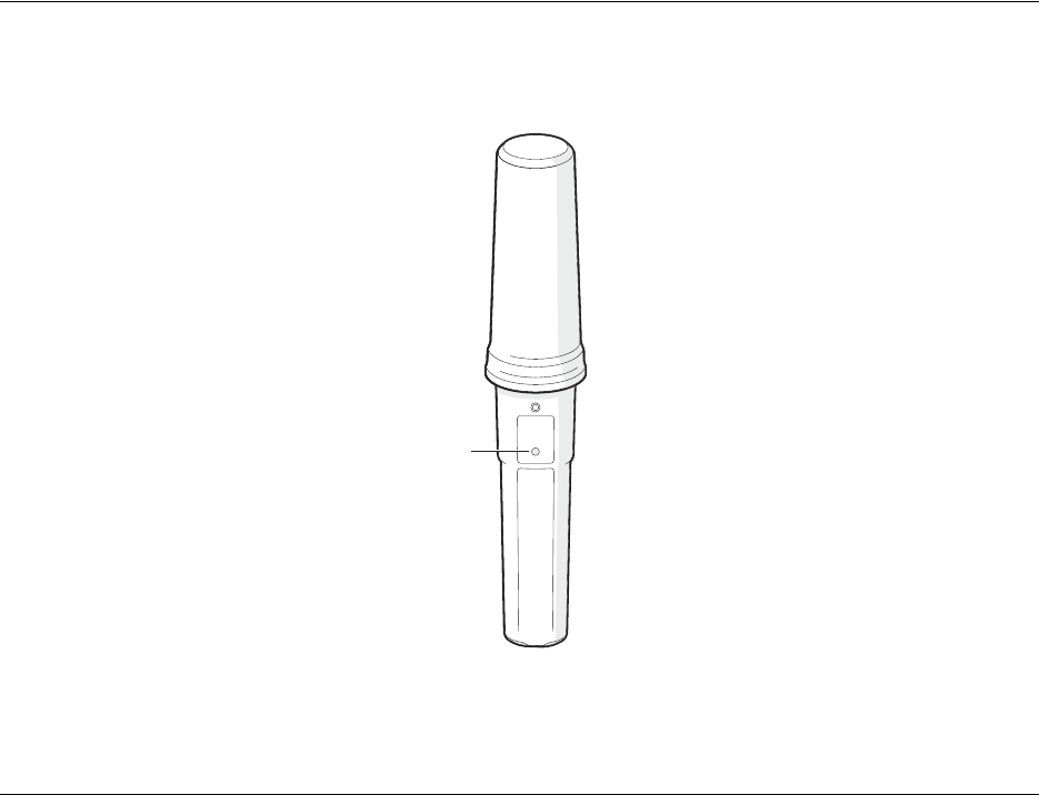
Figure 1 AtoN Express package contents
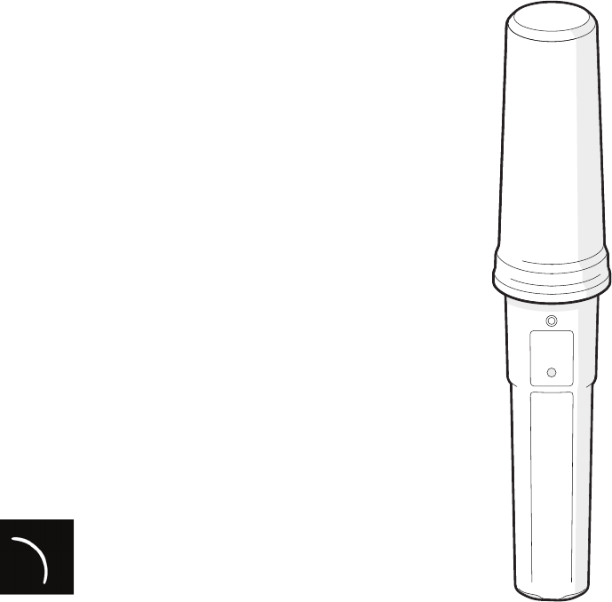
AtoN Express
The AtoN Express AIS Aid-to-Navigation device. The AtoN Express is self-contained and incorporates a rechargeable battery pack,
VHF antenna and GPS antenna.
AtoN Express
Conguration dock
Bracket and xings
Product CD
USB Cable
Power
AtoN Express Power Adapter
SRT Marine
System Solutions
Power Box

Installing and charging the AtoN Express
Page 6
AtoN bracket and fixings
The bracket is used to attach the AtoN Express to the physical AtoN.
Configuration dock
The configuration dock is used to connect the AtoN Express to a PC during configuration. The configuration dock can also be used to
charge the AtoN Express.
USB Cable
The USB Cable is used to connect the configuration dock to the PC.
CD
The CD contains the configuration software and this user manual in PDF format.
Power Box
The Power Box is used to power the AtoN Express from an external power source.
Installing and charging the AtoN Express
Page 7
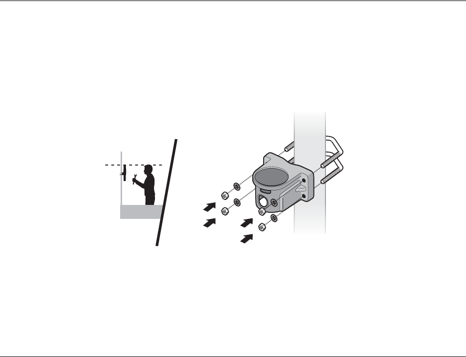
3.2 Installing the AtoN Express bracket
The AtoN Express must be located in the supplied mounting bracket when in use. Insertion into the bracket activates the AtoN Express
and the AtoN Express is inactive when removed from the bracket.
The bracket should be fixed to the structure to be marked using the supplied u-bolts, washers and nuts as shown in Figure 2. The
bracket should be mounted to a non-metallic vertical pole and installed in a location where the status indicator is visible. Ideally the AtoN
Express should be installed approximately 2m above sea level. The area around and above the AtoN Express should be clear from any
obstructions as these may affect GPS reception and / or VHF transmission range.
Ensure that the AtoN Express bracket is installed in the orientation shown in Figure 2.
Figure 2 Installing the AtoN Express bracket
Installing and charging the AtoN Express
Page 8
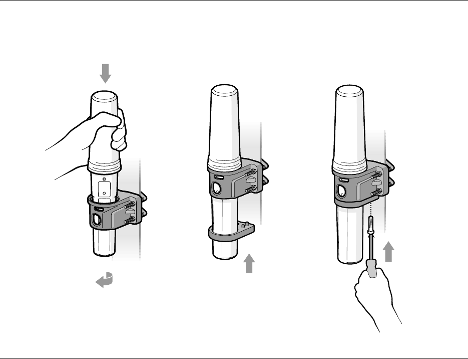
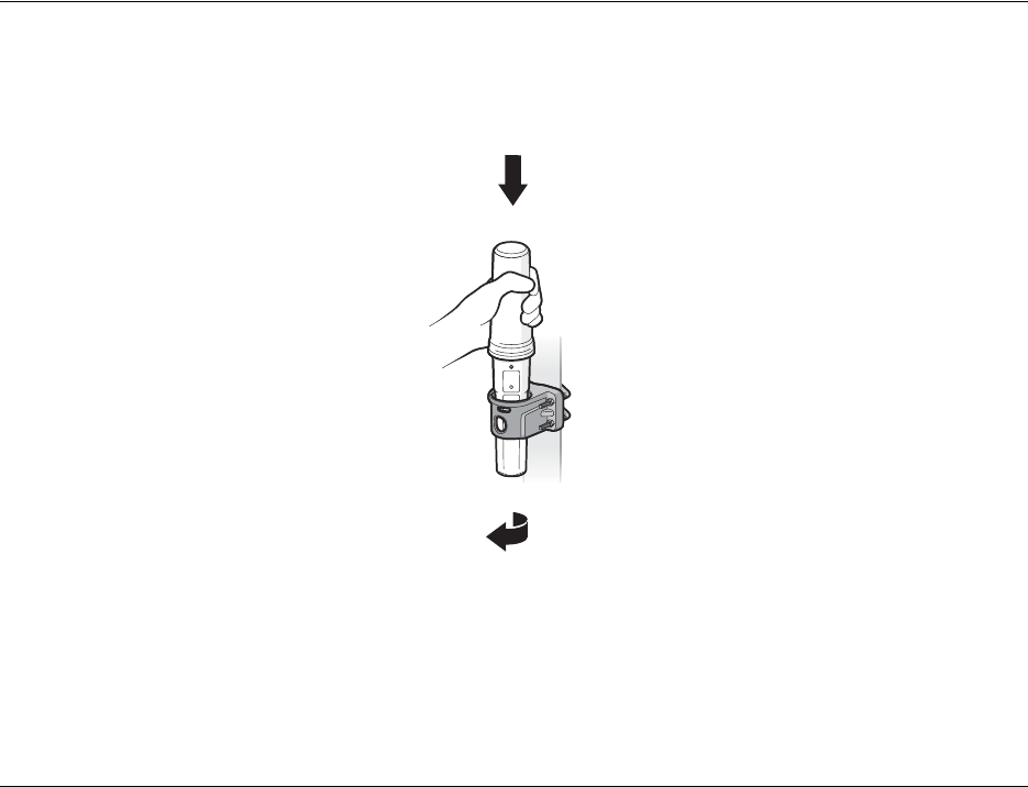
3.3 Fitting the AtoN Express to Bracket
Lower the AtoN Express into the AtoN Express Bracket and rotate clockwise until it clicks into place. Slide the locking collar up to the
underside of the bracket as shown in Figure 3 and secure using the anti-tamper screw supplied in the fixing kit.
Figure 3 Fitting the AtoN Express into the bracket
2
13
Installing and charging the AtoN Express
Page 9
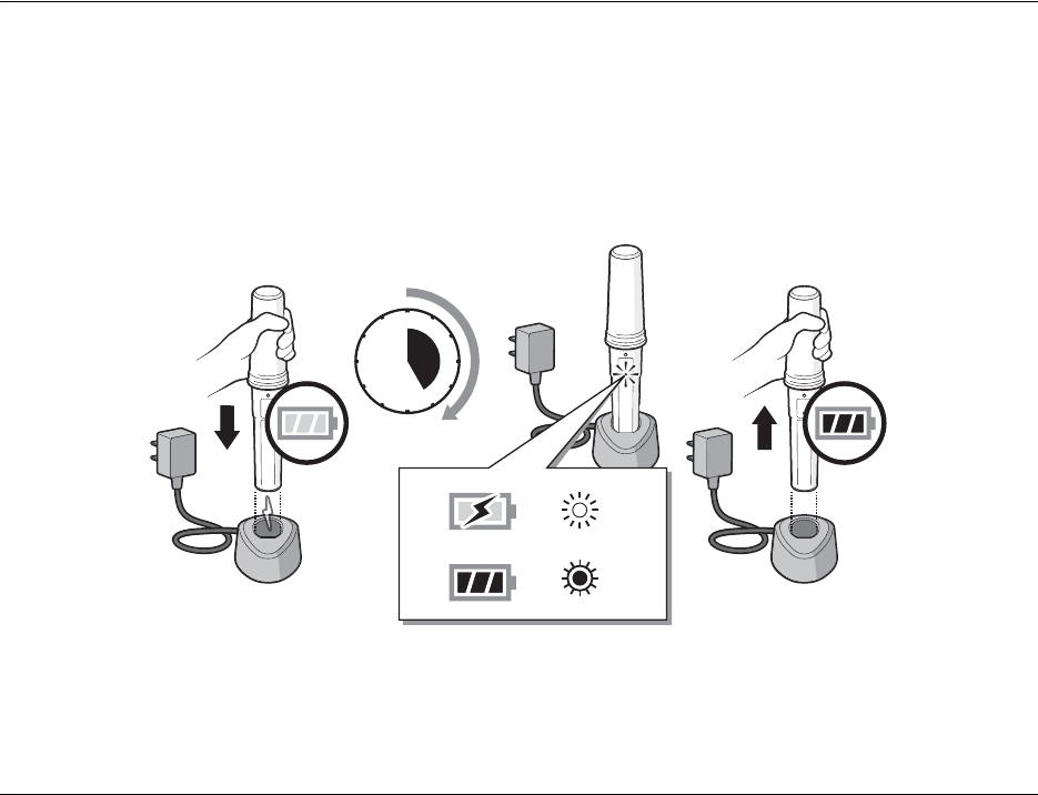
3.4 Charging the AtoN Express
The AtoN Express is shipped with a partial charge and requires a full charge prior to installation on a structure to be marked (unless the
unit is powered via the Power box). The AtoN Express is charged by placing it in the configuration dock as shown in Figure 4.
During charging the status indicator will flash blue at a steady rate (1 second on - 5 seconds off). When charging is complete the status
indicator will flash a shorter blue flash (100 milliseconds on - 5 seconds off). Depending on the condition of the battery a full charge can
take up to 5 hours to complete.
Note that the AtoN Express can be configured as described in section 4 prior to charging.
Figure 4 Charging the AtoN Express
123 4
12
3
1
2
4
5
7
8
10
11
9
6

Installing and charging the AtoN Express
Page 10
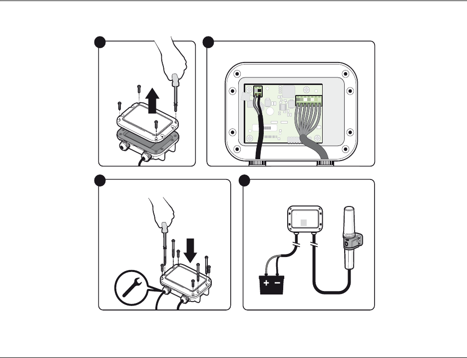
3.5 Installing the Power box
AtoN Express is supplied with a Power Box which can be used to power the unit from an external 12 to 24VDC supply (absolute range
9.6 to 32VDC). The Power Box is waterproof to IPx6 and IPx7.
The Power box also charges the internal battery, so if the external power source fails the AtoN Express will continue working until the
internal battery is exhausted.
The Power Box is supplied with a 6m cable and a connector which mates with the connector at the base of the AtoN Express. The input
power cable is not supplied and will need to be fitted prior to installation.
To fit a power supply cable:
1) Remove the screws at each corner of the power box (see diagram 1).
2) Loosen the cable gland on the pre-fitted cable.
3) Remove the lid of the power box (feeding the attached cable through the gland).
4) Feed the selected power supply cable through the unused gland. A 2 core flexible cable with an external diameter not exceeding
6.5mm should be used.
5) Connect the +ve conductor to the Red screw terminal and -ve conductor to the Black screw terminal (see diagram 2)
6) Carefully feed the cables back through their gland and refit the lid of the power box. Tighten the cable glands and refit the screws
at each corner of the lid (see diagram 3).
7) The power supply can now be attached to the external power source (see diagram 4)
When correctly connected to the external power source the Power Boxes green "Power" LED will be on.
!
The AtoN Express will not charge if the internal temperature is below 0°C or above 40°C. If the temperature is outside
this range the status indicator will flash rapidly to indicate a charging fault.
Installing and charging the AtoN Express
Page 11
Figure 5 Installing the Power Box
1
Remove the
power box lid
3
Power Box
4
Connect the electrical cables
2
Connect the power cable
Red Black
Red Black
Power
AtoN Express Power Adapter
SRT Marine
System Solutions

Configuring the AtoN Express
Page 12
4 Configuring the AtoN Express
The AtoN Express transmits standard AIS AtoN information using message #21. It requires configuration with the relevant information
prior to installation.
The AtoN Express can also be configured for position reporting intervals, VHF operating frequency and other operating parameters
listed below.
Configuration is carried out from a PC running the proAtoN Express application supplied on CD in the configuration pack.
4.1 Installing proAtoN Express - PC
1. Insert the CD into your PC and navigate to the ‘proAtoN Express Installer’. Double click the setup.exe file then follow the on-screen
prompts.
2. If a security warning appears, click 'Install' to continue with the installation.
3. The required drivers will also be installed. Click “Next” on the driver installation pop-up window when prompted to do so.
4. Tha application can be started using the shortcut which is added to the programs menu.
4.2 Connecting to the AtoN Express
Connect to the AtoN Express by inserting it into the configuration dock and connecting the configuration dock USB cable to a PC. The
first time the connection is made the USB drivers must be installed.
Once the drivers are installed, launch the proAtoN Express application. The connection will be attempted automatically if the PC is
connected to the configuration dock. If the automatic connection is not possible the available ports are listed in a drop down menu and
can be manually selected. Connect and Disconnect buttons are available to control the connection. The disconnect button should be
used before physically disconnecting the AtoN express from the PC.

Configuring the AtoN Express
Page 13
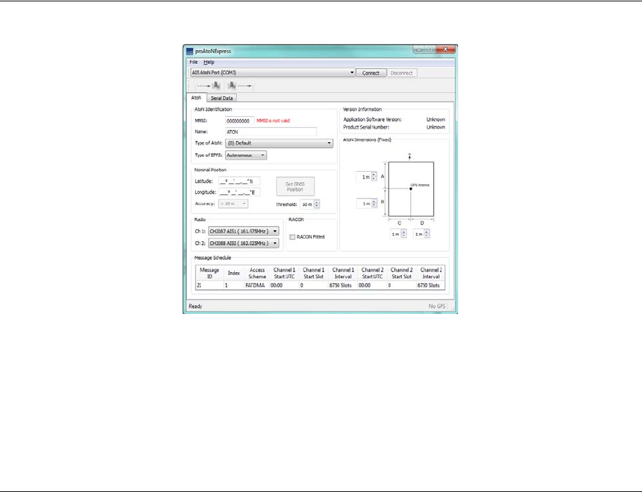
4.3 Basic configuration
All basic configuration is presented on the proAtoN Express configuration tab as shown in Figure 6. This tab permits configuration of the
following information:
•AtoN name
Enter the AtoN name or other identification.
• MMSI number
Enter the AIS AtoN’s 9 digit MMSI number.
• AtoN type
Select the most appropriate AtoN type from the drop down list.
• Type of EPFS
The EPFS used by the AtoN can be set to either Autonomous (uses the GNSS fix) or Surveyed (uses the nominal position entered).
For surveyed positions the accuracy of the measurements (less than or greater than 10m) can be added.
• Nominal Position
The charted (or intended) location of the structure being marked.
• Off Position Threshold.
The distance (m) by which the AtoN my vary from its nominal position before it reports being off position.
•RACON Fitted.
Allows the setting of the racon fitted flag in the message #21 to indicated that a radar beacon is also available at the reported loca-
tion.
• Message Schedule
The start slot, interval between messages and start UTC for both channels A and B can be configured for the message #21.
• AtoN’s dimensions
Enter the AtoN dimensions, referenced to the location of the AtoN Express, to the nearest whole metre.
• Configuration of AIS operating frequencies
Select the required operating VHF frequencies for transmissions. The default channels are Channel A = 161.975MHz and Channel
B = 162.025MHz. The default channels are intenationally reserved for AIS and should not normally be adjusted. For specific applica-
tions the frequencies can be adjusted, but it is critical that they match the configuration of any receiving equipment.
To copy the configuration to the AtoN Express click the send icon. Existing configurations can be retrieved from the AtoN Express using
the retrieve icon.
Configuring the AtoN Express
Page 14
Figure 6 proAtoN Express configuration tab
4.4 Message Schedule Configuration
AtoN Express only transmits the standard AtoN message #21 using FATDMA. The scheduling of this message can be configured using
the following parameters which can be can be entered independently for both channel A and B:
FATDMA (Fixed Access Time Division Multiple Access) access scheme requires that the AIS AtoN is configured with fixed AIS time
slots in which it will transmit AIS messages. Mobile AIS stations operating in the area where an AIS AtoN is installed need to be aware
of the time slots allocated to the AIS AtoN. The slots allocated to the AIS AtoN are 'reserved' by transmissions from an AIS Base Station
that is operating in the same area as the AIS AtoN and is configured to make the necessary slot reservations. In some areas, where
there is no base station coverage, local regulations may allow an AIS AtoN using FATDMA to be installed with out the slot reservation
being made.

Configuring the AtoN Express
Page 15
•Start UTC
The offset from UTC 00:00. This parameter is used to create different start times for the two channels when alternating transmission
between the two channels. For example; a five minute transmission schedule alternating between channel A and B would have a
slot interval of 22500 (10 * 2250 slots per minute) and a difference of 5 minutes between the start UTC’s of the two channels.
•Start Slot
As FATDMA is being used, the start slot should be reserved by the local base station. The start slot can be entered independently for
both channels A and B.
• Channel Interval
This determines the time between transmissions on each channel. The interval is set as a number of slots. 2250 slots = 1 minute.
The operating time from a complete charge is dependent on the configured reporting intervals. Shorter reporting
intervals will reduce the operating time. The examples provided here are intended as a guide as actual operating time
also depends on external factors such as temperature and GPS signal quality.
!
Using the AtoN Express
Page 17
5.1 Activating and deactivating the AtoN Express
The AtoN Express is activated by placing it in the supplied vessel bracket and de-activated when removed from the bracket. The AtoN
Express will continue to report position and vessel data as configured in the incorrect bracket.To activate the AtoN Express insert and
lock into the vessel bracket as shown in Figure 8.
Figure 8 Activating the AtoN Express
The AtoN Express will only fit into the bracket in one orientation, as shown in Figure 8. Do not try to force the AtoN Express into the
bracket in the wrong orientation.
1
2

Using the AtoN Express
Page 18
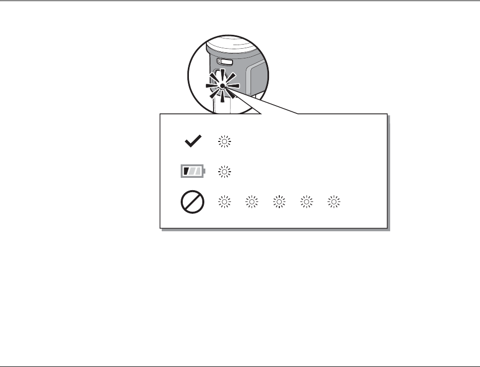
5.2 Status indicator
While active in the fixing bracket
The status indicator shows the current operating state of the AtoN Express. The status indicator flashes green or yellow every 5
seconds. The number of flashes indicates the status conditions defined in the table below. The key status indications are also shown in
Figure 9
While in the configuration dock
The status indicator shows the current operating state of the AtoN Express. The status indicator flashes blue every 5 seconds. The
duration of the flashes indicates the charging status conditions defined in the table below.
.
Number of flashes Status
1 Green AtoN Express is active and operating normally.
2 Yellow Low battery warning (<50%), AtoN Express
continues to operate until battery is exhausted.
3 Yellow Error condition - please contact your dealer for
support.
5 Yellow Waiting for GPS fix or no GPS fix. If this condition
persists for more than 12 minutes, relocate the AtoN
Express to a location with a clear sky view.
6 Yellow Transmit time out - AtoN Express is unable to
transmit due to AIS network congestion.
7 Yellow No MMSI programmed. The AtoN Express is unable
to transmit because no MMSI has been configured.
1 Blue (1 second) Charging.
1 Blue (100 millisecond) Charged.
1 Blue (3 seconds) Charging error.
Using the AtoN Express
Page 19
Figure 9 Identified common status indications - while active
While charging
The status indicator flashes blue (one second on - five seconds off). When charging is complete the status indicator will flash a shorter
er blue flash (one millisecond on - five seconds off). A charging error is indicated by a longer blue flash (three seconds on - 5 seconds
off) of the status indicator. The most likely cause of a charging error is high temperature. The charger will not operate above 40°C for
safety reasons.
GPS
GREEN
YELLOW

Troubleshooting
Page 20
6 Troubleshooting
Issue Possible cause and remedy
The AtoN Express status indicator does not
flash when placed in the holder. • The AtoN Express is in ‘deep sleep’ mode and requires charging in order to
activate for use.
• The AtoN Express battery is exhausted and requires charging.
The AtoN Express status indicator periodically
flashes more than once when placed in the
holder.
• Please refer to the status indicator description in section 5.2.
The AIS transmission range of the AtoN
Express is reduced. • The AtoN Express should be mounted as high as possible on the vessel and
should not be attached to a vertical metal surface or pole as this will interfere
with the operation of the internal VHF antenna.
The AtoN Express does not obtain a GPS
position fix (status indicator flashes 5 times). • Ensure that the AtoN Express is installed outdoors with a clear unobstructed
view of the sky.
• Avoid locating the AtoN Express close to large metal structures.
The AtoN Express status indicator does not
flash when the AtoN Express is placed in the
configuration dock.
• Remove the AtoN Express from the configuration dock and re-insert.
• Check that the configuration dock is plugged into a mains outlet and that the
outlet is live.
The AtoN Express status indicator flashes
Blue slowly (3 seconds on - 5 seconds off)
when the AtoN Express is being charged.
• The temperature is too high or low to safely charge the battery. Move the
AtoN Express to a location where the temperature is between 0°C and 40°C.
• A charging error has occurred - please contact your dealer.
The Power indicator of the Power Box (where
used) is not illuminated. • The power supply to the Power Box may not be connected.

Specification
Page 21
7 Specification
Parameter Value
Dimensions 350mm x 63mm max. diameter (without bracket)
Weight 250g (AtoN Express unit only)
Power Built in 2200mAh Lithium-Ion battery pack
Charger 100-240VAC input, 5V 1.2A output.
GPS receiver 50 channel receiver and internal GPS antenna
VHF transmitter frequency range 156.025 to 162.025MHz
Transmitter output power 1W radiated (EIRP)
Power Consumption (from internal battery) <0.4Ah/day
Power Consumption (from external 12v supply) <1 Ah/day
Channel bandwidth 25kHz
Modulation mode 25kHz GMSK
Environmental IEC60945 ‘Exposed’ category
Waterproof to IPx6 and IPx7
Operating temperature -15°C to 55°C

Specification
Page 22

201-0470:1
SRT Marine
System Solutions