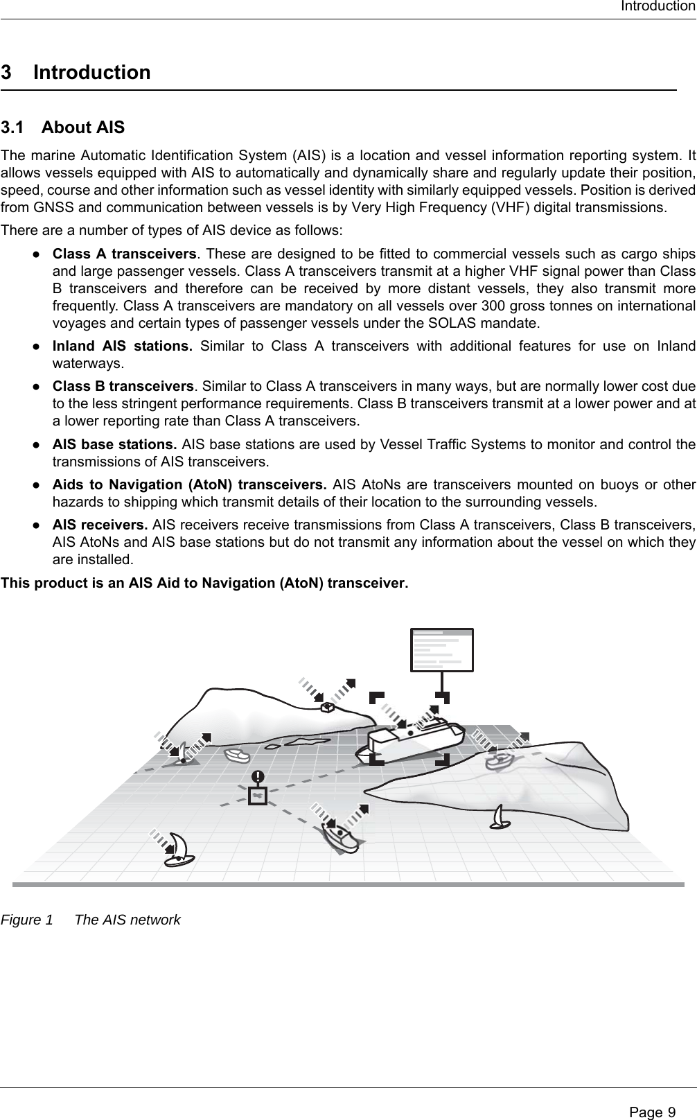
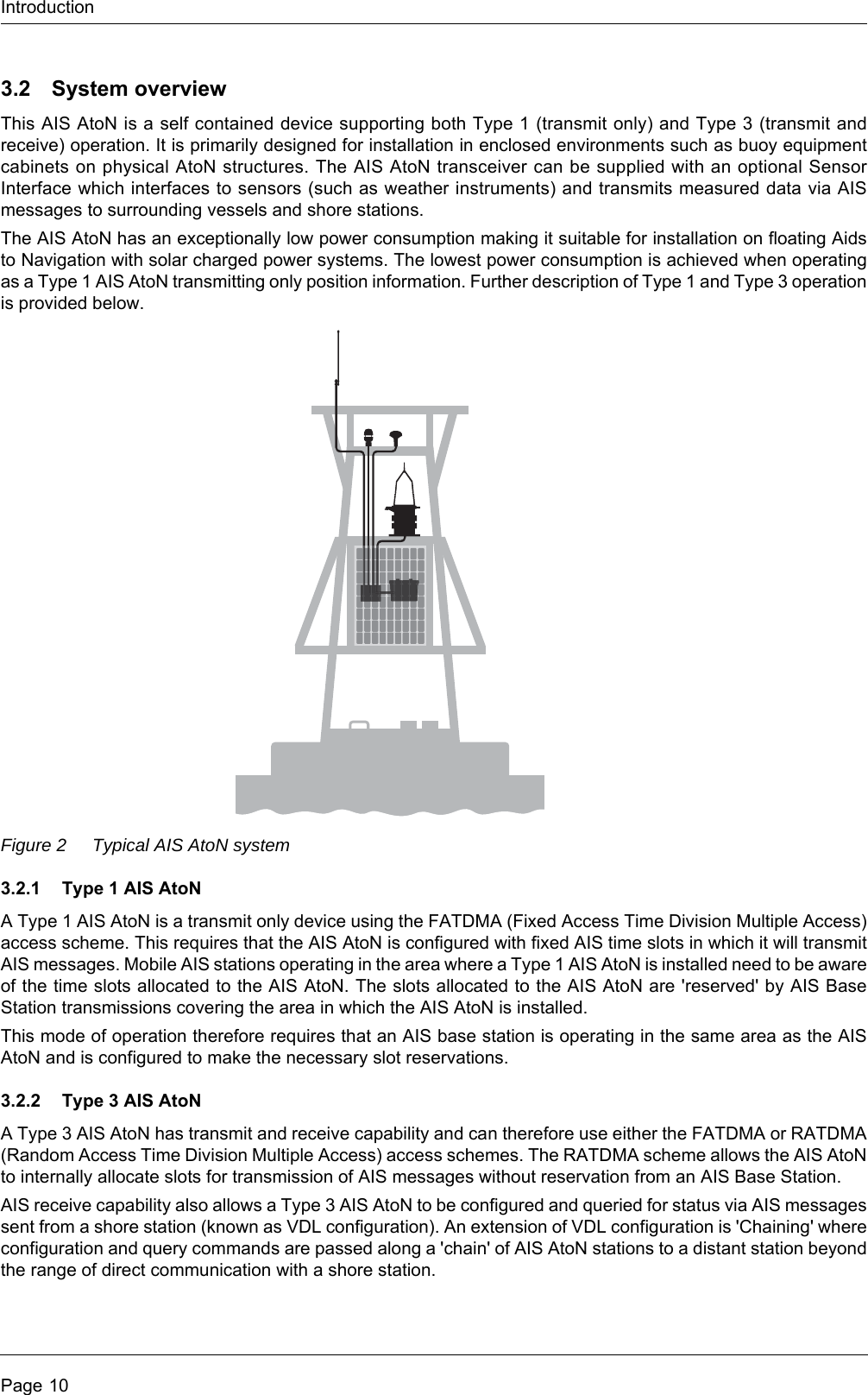
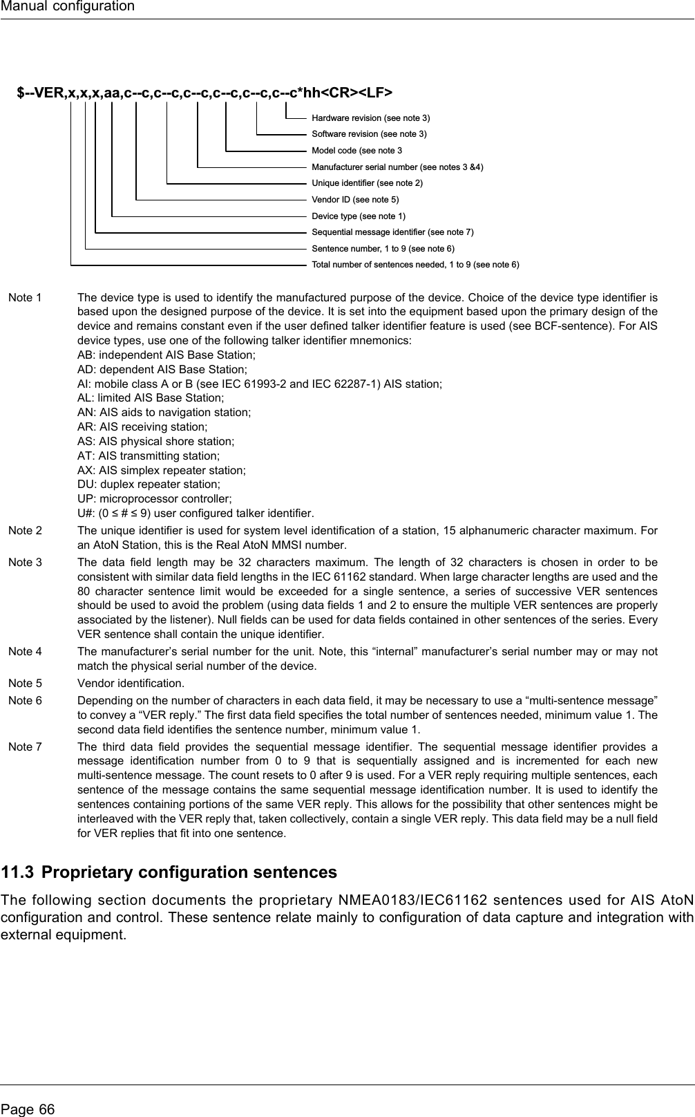
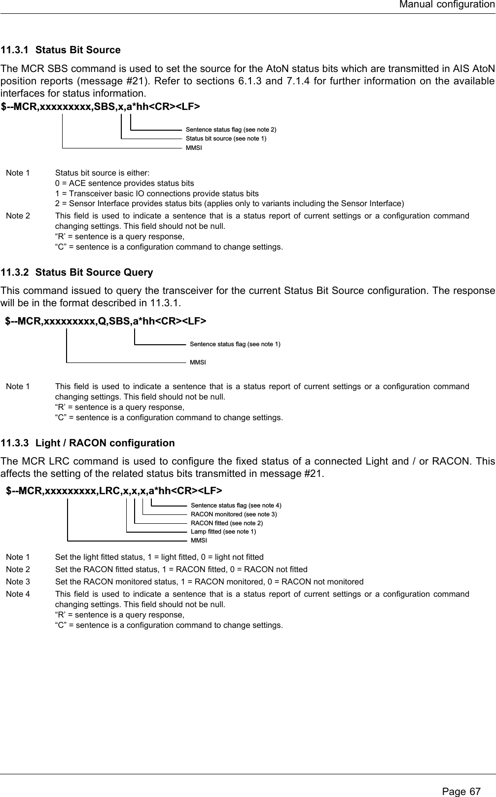
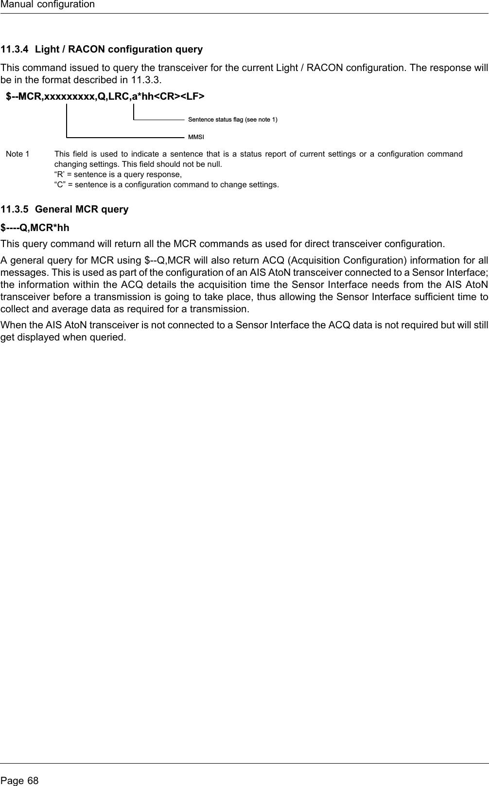
SRT Marine Systems plc 4180051 AIS AtoN Transceiver User Manual Chronos manual

Software Radio Technology plc AIS AtoN Transceiver Chronos manual

User manual

Chronos AIS Aids to Navigation TransceiverChronos AIS AtoN Sensor InterfaceInstallation and operation manual201-0636:1
 Page 1Table of contents1 Glossary............................................................................................... 52 Notices ................................................................................................. 62.1 Safety warnings ................................................................................................................................. 62.2 General notices.................................................................................................................................. 62.3 Regulatory information....................................................................................................................... 73 Introduction ......................................................................................... 93.1 About AIS........................................................................................................................................... 93.2 System overview.............................................................................................................................. 103.3 Supported AIS messages ................................................................................................................ 114 AIS AtoN product variants ............................................................... 135 Installation ........................................................................................ 145.1 What’s in the box (AIS AtoN transceiver) ........................................................................................ 155.2 What’s in the box (Sensor Interface) ............................................................................................... 165.3 Preparing for installation .................................................................................................................. 175.4 Mounting the AIS AtoN transceiver and Sensor Interface ............................................................... 186 Transceiver and Sensor Interface connections ............................. 196.1 AIS AtoN transceiver connections ................................................................................................... 196.2 Sensor Interface connections .......................................................................................................... 227 Connecting external sensors and systems.................................... 237.1 Connecting sensors and systems to the AIS AtoN Transceiver  ..................................................... 237.2 Connecting sensors and systems to the Sensor Interface .............................................................. 248 Configuration using proAtoN .......................................................... 318.1 proAtoN installation.......................................................................................................................... 318.2 Application layout............................................................................................................................. 328.3 AIS AtoN transceiver configuration.................................................................................................. 338.4 Transceiver diagnostics ................................................................................................................... 428.5 Sensor configuration ....................................................................................................................... 458.6 Other features.................................................................................................................................. 499 Operation ........................................................................................... 509.1 Standby operation............................................................................................................................ 5010 Data messages and data sources ................................................... 5110.1 Configurations without the Sensor Interface.................................................................................... 5110.2 Configurations with the Sensor Interface......................................................................................... 5111 Manual configuration........................................................................ 5911.1 Basic Type 1 AIS AtoN configuration (FATDMA operation) ............................................................ 5911.2 NMEA0183 / IEC61162 configuration sentences ............................................................................ 5911.3 Proprietary configuration sentences ................................................................................................ 6512 Technical specification .................................................................... 68
Page 212.1 Applicable equipment standards...................................................................................................... 6812.2 AIS AtoN transceiver specification................................................................................................... 6812.3 Sensor Interface specification ......................................................................................................... 7012.4 Configuration interface specification................................................................................................ 7112.5 Drawings and dimensions................................................................................................................ 7213 Firmware upgrade procedure .......................................................... 73
 Page 3Table of figuresFigure 1 The AIS network ........................................................................................................................... 9Figure 2 Typical AIS AtoN system ............................................................................................................ 10Figure 3 Typical AIS AtoN transceiver system connections ..................................................................... 14Figure 4 Typical AIS AtoN transceiver and Sensor Interface system connections ................................... 14Figure 5 What’s in the box (AIS AtoN transceiver) ................................................................................... 15Figure 6 What’s in the box (Sensor Interface) .......................................................................................... 16Figure 7 Mounting the AIS AtoN transceiver and Sensor Interface .......................................................... 18Figure 8 Transceiver connector locations................................................................................................. 19Figure 9 Pin numbering for the 18 way Link connector.............................................................................20Figure 10 Sensor Interface connections ..................................................................................................... 22Figure 11 Pin numbering for Sensor 1 and Sensor 2 connectors ............................................................... 25Figure 12 Light current sense loop circuit................................................................................................... 27Figure 13 Isolated digital input internal reference circuit and examples of external circuits ....................... 28Figure 14 Non-isolated digital input reference circuit and examples of external circuits ............................ 29Figure 15 Relay drive output reference circuit ............................................................................................ 30Figure 16 proAtoN application layout.......................................................................................................... 32Figure 17 proAtoN tab synchronisation icons ............................................................................................. 33Figure 18 proAtoN message schedule tab layout....................................................................................... 35Figure 19 Example FATDMA schedule....................................................................................................... 37Figure 20 Example RATDMA schedule ...................................................................................................... 38Figure 21 Virtual AtoN configuration tab layout .......................................................................................... 39Figure 22 Status input configuration tab layout........................................................................................... 40Figure 23 Alert messages configuration tab layout..................................................................................... 41Figure 24 Initial sensor settings tab ............................................................................................................ 45Figure 25 Sensor settings tab..................................................................................................................... 45Figure 26 ADC settings tab......................................................................................................................... 46Figure 27 Message settings tab.................................................................................................................. 47Figure 28 System information tab............................................................................................................... 48Figure 29 Live data tab ............................................................................................................................... 49Figure 30 AIS AtoN Transceiver dimensions.............................................................................................. 72Figure 31 Sensor Interface dimensions ...................................................................................................... 72Figure 32 vxsend utility screenshot............................................................................................................. 73
Page 4List of tablesTable 1 Pin numbers and functions for the supplied 18 way backshell connector .................................. 21Table 2 Pin numbers and functions for the Sensor Interface Sensor 1 connector .................................. 25Table 3 Pin numbers and functions for the Sensor Interface Sensor 2 connector .................................. 26Table 4 General Extended Sensor Interface Configuration Commands.................................................. 53Table 5 Zeni Lite Message #6 Configuration commands ........................................................................ 54Table 6 ADC configuration commands.................................................................................................... 55Table 7 Data mapping for message #6 DAC 235, FI 10.......................................................................... 56Table 8 Data mapping for message #6 Zeni Lite format.......................................................................... 57Table 9 Sensor Configuration Options..................................................................................................... 58
Glossary Page 51 GlossaryAIS Automatic Identification SystemAtoN Aid to NavigationBIIT Built In Integrity TestFATDMA Fixed Access Time Division Multiple AccessGLONASS Global Navigation Satellite System (term specific to the satellite navigation system operated by the Russian Federation)GNSS Global Navigation Satellite system (general term used to refer to any satellite navigation system)GPS Global Positioning SystemIALA International Association of Marine Aids to Navigation and Lighthouse AuthoritiesIEC International Electrotechnical commissionITU International Telecommunication UnionMID (in the context of MMSI) Maritime Identification DigitsMMSI Maritime Mobile Service IdentityNMEA National Marine Electronics AssociationRACON RAdar beaCON, A radar transponder used to mark navigational hazards.RATDMA Random Access Time Division Multiple AccessRS232 Serial data communications standard - see TIA-232-FRS422 Serial data communications standard see TIA-422-BSART Search And Rescue TransponderSOLAS Safety of Life at SeaSDI-12 Serial Data Interface at 1200 BaudUSB Universal Serial BusUTC Coordinated Universal TimeVDL VHF Data LinkVHF Very High FrequencyVSWR Voltage Standing Wave Ratio
NoticesPage 62NoticesWhen reading this manual please pay particular attention to warnings marked with the warning triangle symbol shown on the left. These are important messages for safety, installation and usage of the transceiver.2.1 Safety warnings2.2 General notices2.2.1 Position sourceAll marine Automatic Identification System (AIS) transceivers utilise a satellite based location system such as the Global Positioning Satellite (GPS) network. The general term for satellite based location systems is Global Navigation Satellite System or GNSS. This manual refers to either GNSS or GPS depending on context.2.2.2 Product categoryThis product is categorised as 'exposed' in accordance with the definitions provided in IEC 60945.2.2.3 Disposal of the product and packagingPlease dispose of this product in accordance with the European WEEE Directive or with the applicable local regulations for disposal of electrical equipment. Every effort has been made to ensure the packaging for the product is recyclable. Please dispose of the packaging in an environmentally friendly manner.2.2.4 Accuracy of this manualThis manual is intended as a guide to the installation, setup and use of this product. Every effort has been made to ensure the accuracy of this manual, however due to continuous product development this manual may not be accurate in all respects, therefore no guarantee is offered. If you are in any doubt about any aspect of this product, please contact your supplier.The part number and revision number of this manual are shown on the lower right hand corner of the front cover. !This equipment must be installed in accordance with the instructions provided in this manual. Failure to do so will seriously affect its performance and reliability. It is strongly recommended that a trained technician installs and configures this product.This equipment is intended as an aid to navigation and is not a replacement for proper navigational judgement. Information provided by the equipment must not be relied upon as accurate. User decisions based upon information provided by the equipment are done so entirely at the users own risk.!!The accuracy of a GNSS position fix is variable and affected by factors such as the antenna positioning, how many satellites are used to determine a position and for how long satellite information has been received.!
Notices Page 72.3 Regulatory information2.3.1 Declaration of conformity - R&TTEWe, SRT Marine System Solutions Ltd, of Wireless House, Westfield Industrial Estate, Midsomer Norton, Bath, BA3 4BS declare under our own responsibility that the product Chronos AIS AtoN transceiver to which this declaration refers conforms to the relevant sections of the following standards and / or other normative documents.For Article 3.1 (a) [Health & Safety]:EN60950-1:2006/A2:2013, relevant sections not addressed by IEC60945:2002-08IEC 60945:2002-08For Article 3.1 (b) [EMC]:IEC 60945:2002-08For Article 3.2 [Spectrum usage]:IEC62320-2:2008IEC61108-1:2003-07For Article 3.3 [Special requirements]:IEC62320-2:2008We, SRT Marine System Solutions Ltd, declare that all essential radio test suites have been carried out and the above named product is in conformity with all essential requirements of Directive 1999/5/EC.The conformity assessment procedure referred to in Article 10 and detailed in Annex [III] and [IV] of Directive 1999/5/EC has been followed with the involvement of the following Notified Body.TÜV SÜD BABT. Octagon House, Concorde Way, Segensworth North, Fareham, Hampshire PO15 5RL England. Identification mark: 0168.The technical documentation relevant to the above equipment will be held at: SRT Marine Solutions Ltd, Wireless House, Westfield Industrial Estate, Midsomer Norton, Bath, BA3 4BS, England.Tel:+44 1761 409500www.srt-marinesystems.comName: Neil Peniket, Chief Operating OfficerDate: 26th January 20152.3.2 CE MarkingThe product carries the CE mark, notified body number and alert symbol as required by the R&TTE directive.The product is intended for sale in the following member states:Great Britain, France, Spain, Sweden, Austria, Netherlands, Portugal, Denmark, Norway, Belgium, Italy, Finland, Ireland, Luxembourg, Germany, Czech Republic, Bulgaria, Cyprus, Estonia, Greece, Hungary, Iceland, Latvia, Lithuania, Malta, Romania, Slovak Republic, Slovenia, Switzerland/Liechtenstein, Poland.Restrictions of use: Some EU member states may require a licence to operate this equipment.
NoticesPage 82.3.3 FCC and Industry Canada noticesA. FCC Part 15.19(a) statement:This device complies with part 15 of the FCC Rules. Operation is subject to the following two conditions: (1) This device may not cause harmful interference, and (2) this device must accept any interference received, including interference that may cause undesired operation.A. Part 15 Clause 15.105 [EMC Class A/B statement]:Note: This equipment has been tested and found to comply with the limits for a Class B digital device, pursuant to part 15 of the FCC Rules. These limits are designed to provide reasonable protection against harmful interference in a residential installation. This equipment generates, uses and can radiate radio frequency energy and, if not installed and used in accordance with the instructions, may cause harmful interference to radio communications. However, there is no guarantee that interference will not occur in a particular installation. If this equipment does cause harmful interference to radio or television reception, which can be determined by turning the equipment off and on, the user is encouraged to try to correct the interference by one or more of the following measures:- Reorient or relocate the receiving antenna.- Increase the separation between the equipment and receiver.- Connect the equipment into an outlet on a circuit different from that to which the receiver is connected.- Consult the dealer or an experienced radio/TV technician for help.B. Part 15 Clause 15.21 [Do not modify warning]Changes or modifications not expressly approved by the party responsible for compliance could void the user's authority to operate the equipment.C. RSS-Gen license-exempt notice:This device complies with Industry Canada licence-exempt RSS standard(s). Operation is subject to the following two conditions: (1) this device may not cause interference, and (2) this device must accept any interference, including interference that may cause undesired operation of the device.Le présent appareil est conforme aux CNR d'Industrie Canada applicables aux appareils radio exempts de licence. L'exploitation est autorisée aux deux conditions suivantes : (1) l'appareil ne doit pas produire de brouillage, et (2) l'utilisateur de l'appareil doit accepter tout brouillage radioélectrique subi, même si le brouillage est susceptible d'en compromettre le fonctionnement.D. RSS-Gen antenna notice:Under Industry Canada regulations, this radio transmitter may only operate using an antenna of a type and maximum (or lesser) gain approved for the transmitter by Industry Canada. To reduce potential radio interference to other users, the antenna type and its gain should be so chosen that the equivalent isotropically radiated power (e.i.r.p.) is not more than that necessary for successful communication.Conformément à la réglementation d'Industrie Canada, le présent émetteur radio peut fonctionner avec une antenne d'un type et d'un gain maximal (ou inférieur) approuvé pour l'émetteur par Industrie Canada. Dans le but de réduire les risques de brouillage radioélectrique à l'intention des autres utilisateurs, il faut choisir le type d'antenne et son gain de sorte que la puissance isotrope rayonnée équivalente (p.i.r.e.) ne dépasse pas l'intensité nécessaire à l'établissement d'une communication satisfaisante. E. FCC & IC  RF Exposure related informationRF Exposure Guidance: This equipment complies with FCC and Industry Canada radiation exposure limits set forth for an uncontrolled environment. This equipment should be installed and operated with minimum distance 20cm between the radiator and your body. This transmitter must not be co-located or operating in conjunction with any other antenna or transmitter not described under this FCC ID and IC certification number, except in accordance with FCC and Industry Canada multi-transmitter product procedures.Guide d'Exposition RF : ce matériel est conforme aux normes FCC et Industrie Canada relatives aux limites maximales d'exposition aux radiations en milieu non-contrôlé. Cet équipement doit être installé et opéré à une distance de plus de 20cm entre la source de radiation et le corps de l'utilisateur. Cet émetteur ne peut être situé à proximité de ou opérer conjointement avec tout autre émetteur ou toute antenne non-classifiés sous le numéro de certification FCC ID et IC, sauf s'ils respectent la procédure FCC et Industrie Canada concernant tout produit multi-émetteurs.
Introduction Page 93Introduction3.1 About AISThe marine Automatic Identification System (AIS) is a location and vessel information reporting system. It allows vessels equipped with AIS to automatically and dynamically share and regularly update their position, speed, course and other information such as vessel identity with similarly equipped vessels. Position is derived from GNSS and communication between vessels is by Very High Frequency (VHF) digital transmissions. There are a number of types of AIS device as follows:●Class A transceivers. These are designed to be fitted to commercial vessels such as cargo ships and large passenger vessels. Class A transceivers transmit at a higher VHF signal power than Class B transceivers and therefore can be received by more distant vessels, they also transmit more frequently. Class A transceivers are mandatory on all vessels over 300 gross tonnes on international voyages and certain types of passenger vessels under the SOLAS mandate.   ●Inland AIS stations. Similar to Class A transceivers with additional features for use on Inland waterways. ●Class B transceivers. Similar to Class A transceivers in many ways, but are normally lower cost due to the less stringent performance requirements. Class B transceivers transmit at a lower power and at a lower reporting rate than Class A transceivers. ●AIS base stations. AIS base stations are used by Vessel Traffic Systems to monitor and control the transmissions of AIS transceivers. ●Aids to Navigation (AtoN) transceivers. AIS AtoNs are transceivers mounted on buoys or other hazards to shipping which transmit details of their location to the surrounding vessels. ●AIS receivers. AIS receivers receive transmissions from Class A transceivers, Class B transceivers, AIS AtoNs and AIS base stations but do not transmit any information about the vessel on which they are installed. This product is an AIS Aid to Navigation (AtoN) transceiver.Figure 1 The AIS network
IntroductionPage 103.2 System overviewThis AIS AtoN is a self contained device supporting both Type 1 (transmit only) and Type 3 (transmit and receive) operation. It is primarily designed for installation in enclosed environments such as buoy equipment cabinets on physical AtoN structures. The AIS AtoN transceiver can be supplied with an optional Sensor Interface which interfaces to sensors (such as weather instruments) and transmits measured data via AIS messages to surrounding vessels and shore stations.The AIS AtoN has an exceptionally low power consumption making it suitable for installation on floating Aids to Navigation with solar charged power systems. The lowest power consumption is achieved when operating as a Type 1 AIS AtoN transmitting only position information. Further description of Type 1 and Type 3 operation is provided below.Figure 2 Typical AIS AtoN system3.2.1 Type 1 AIS AtoNA Type 1 AIS AtoN is a transmit only device using the FATDMA (Fixed Access Time Division Multiple Access) access scheme. This requires that the AIS AtoN is configured with fixed AIS time slots in which it will transmit AIS messages. Mobile AIS stations operating in the area where a Type 1 AIS AtoN is installed need to be aware of the time slots allocated to the AIS AtoN. The slots allocated to the AIS AtoN are 'reserved' by AIS Base Station transmissions covering the area in which the AIS AtoN is installed. This mode of operation therefore requires that an AIS base station is operating in the same area as the AIS AtoN and is configured to make the necessary slot reservations.3.2.2 Type 3 AIS AtoNA Type 3 AIS AtoN has transmit and receive capability and can therefore use either the FATDMA or RATDMA (Random Access Time Division Multiple Access) access schemes. The RATDMA scheme allows the AIS AtoN to internally allocate slots for transmission of AIS messages without reservation from an AIS Base Station.AIS receive capability also allows a Type 3 AIS AtoN to be configured and queried for status via AIS messages sent from a shore station (known as VDL configuration). An extension of VDL configuration is 'Chaining' where configuration and query commands are passed along a 'chain' of AIS AtoN stations to a distant station beyond the range of direct communication with a shore station.
Introduction Page 113.3 Supported AIS messagesThe transceiver supports the following AIS message types.ITU-R M.1371-4 Message numberDescriptionTransmitted / Received by AtoN TransceiverApplication6Binary addressed message Transmitted and receivedThe transceiver uses message 6 to send binary data (relating to connected sensors and systems) to a specific shore station. The transceiver can also receive addressed binary messages for the purpose of configuration and control.7Binary acknowledge message Transmitted and receivedThis message is transmitted to acknowledge receipt of a binary message. The transceiver can also receive acknowledgements relating to its own addressed binary transmissions.8Binary broadcast message TransmittedThe transceiver uses message 8 to broadcast binary data (relating to connected sensors and systems) to all other AIS stations in range.12 Addressed safety related message TransmittedThe transceiver can be configured to transmit an addressed safety related message to a specific shore station to alert the operator to an off position, vessel proximity or built in test failure condition.13Acknowledgement of received addressed safety related messageReceivedThe transceiver receives message 13 in acknowledgement of its transmission of message 12.14 Safety related broadcast message TransmittedThe transceiver can be configured to transmit a broadcast safety related message to all AIS stations in range to warn of an off position, vessel proximity or built in test failure condition.
IntroductionPage 1220 Data link management message ReceivedWhen operating as a Type 3 transceiver slot reservations made by a shore station using message 20 will be observed by the transceiver.21 Aids to Navigation report TransmittedThis is the primary message transmitted by the transceiver. It contains the position, identification and status of the transceiver.25 Single slot binary message Transmitted and receivedThis message can be used for remote (over the air) configuration of the transceiver and configuration of a ‘chain’ of transceivers.ITU-R M.1371-4 Message numberDescriptionTransmitted / Received by AtoN TransceiverApplication
AIS AtoN product variants Page 134 AIS AtoN product variantsThe AIS AtoN transceiver can be operated with or without connection to the optional Sensor Interface product which is available to purchase separately. The AIS AtoN transceiver can be configured to operate as either type 1 or type 3 either with or without connection to the Sensor Interface. Installation of an AIS AtoN transceiver without connection to a Sensor Interface will limit the functionality of the installation to transmission of AIS message 21 including the following information:●Name of AtoN●Position of AtoN●Status of AtoN (including AtoN health, Light health and status and RACON status)Installation without connection to a Sensor Interface is recommended when their is limited power availability and no requirement for the AIS AtoN to broadcast other information such as meteorological or hydrological data. When the AIS AtoN transceiver is installed with a Sensor Interface the capability is extended to enable the broadcasting of data from connected sensors and systems. However the power consumption of the combined AIS AtoN transceiver and Sensor Interface will be higher and therefore suited to an installation where power consumption is less critical. Type 1 AIS AtoN transceiver without Sensor InterfaceType 1 AIS AtoN transceiver with Sensor InterfaceType 3 AIS AtoN transceiver without Sensor InterfaceType 3 AIS AtoN transceiver with Sensor InterfaceA system of icons is used throughout this manual to highlight which AIS AtoN configurations a particular section, paragraph or illustration applies to. Sections without any icons apply to all configurations.!11S33S
InstallationPage 145 Installation The AIS AtoN transceiver has been designed for ease of installation. The transceiver is self contained requiring only an external VHF antenna, GPS antenna and power source for a basic installation. A typical system and connection diagram is provided in Figure 3. The AIS AtoN transceiver can be connected to a Sensor Interface when a more extensive range of sensors and external devices are required as part of the AIS AtoN installation. Figure 4 shows a typical installation with a Sensor Interface included.Figure 3 Typical AIS AtoN transceiver system connectionsFigure 4 Typical AIS AtoN transceiver and Sensor Interface system connectionsThe main installation and commissioning steps are:1. Mount the Transceiver in a suitable location on the physical Aid to Navigation.2. Install a VHF antenna according to the manufacturers instructions.3. Install the supplied GNSS antenna. 4. Connect any sensor interfaces and light / RACON monitoring signals.5. Connect power to the AIS AtoN transceiver and optional Sensor Interface.6. Configure and commission the AIS AtoN transceiver and optional Sensor Interface via USB (note that this step can be carried out on shore prior to installation in a remote location).11S 33SAIS AtoNTransceiverVHF antennaGPS antennaLight (optional)RACON (optional)12/24V DC supplyPC (Conguration only)Earth bond Other sensors andmonitoring equipment(optional)AIS AtoNTransceiverVHF antennaGPS antennaLight (optional)RACON (optional)12/24V DC supply PC (Conguration only)SensorInterfaceEarth bond
Installation Page 155.1 What’s in the box (AIS AtoN transceiver) Figure 5 shows the items included with the AIS AtoN transceiver. The following section gives a brief overview of each item. Please ensure all items are present and if any are missing please contact your supplier.Figure 5 What’s in the box (AIS AtoN transceiver)●AIS AtoN transceiver - The AIS AtoN transceiver unit.●Fixings - Fixing screws for mounting the transceiver to the physical AtoN structure and for connection of the earth stud to a suitable earth point. ●Power and USB cable - Cable for connection of power and USB. ●USB configuration cable - USB cable for connection to a PC when configuring the transceiver. This cable mates with the Power and USB cable. ●Support tools CD - CD containing the product manual, transceiver PC configuration and diagnostic tools (proAtoN). ●Quick Start Guide - A brief introduction to installation and configuration of the AIS AtoN transceiver. ●Backshell connector - Connectors required for making connection to the sensor interfaces as described in section 6.1.2. ●GPS antenna - GPS antenna and 10m cable.13Power and USB cableBackshellconnectorAIS AtoN TransceiverProduct CDGPS antennaUSB conguration cableQuick StartGuideFixings
InstallationPage 165.2 What’s in the box (Sensor Interface) Figure 5 shows the typical items included with the optional Sensor Interface. The following section gives a brief overview of each item. Please ensure all items are present and if any are missing please contact your supplier.Figure 6 What’s in the box (Sensor Interface)●Sensor Interface - The Sensor Interface unit. ●Fixings - Fixing screws for mounting the Sensor Interface to the physical AtoN structure. ●Link cable - Cable for connection of the Sensor Interface to the AIS AtoN transceiver as defined in section 6. ●USB configuration cable - USB cable for connection to a PC when configuring the Sensor Interface. ●Support tools CD - CD containing the product manual, transceiver PC configuration and diagnostic tools (proAtoN). ●Quick Start Guide - A brief introduction to installation and configuration of the Sensor Interface. ●Backshell connectors - Connectors required for making connection to the sensor interfaces as described in section 7.2. 1S3SQuick StartGuideSensor InterfaceProduct CDLink cable FixingsBackshellconnectors (x2)USB conguration cable
Installation Page 175.3 Preparing for installationIn addition to the items provided with the AIS AtoN transceiver and Sensor Interface the following items will be required to complete the installation.5.3.1 Tools and wiring accessoriesThe following tools and wiring accessories are required for installation:●Posidriv screwdriver (size PZ2). ●M4 spanner. ●Soldering equipment for wiring of the connectors included (only required if external sensors are required). ●Suitable multi-core cable for connection of sensor devices via the included backshell connector. The cable should have a minimum outer diameter of 6.5mm and a maximum outer dimension of 9.5mm. It is important to select cable which meets this criteria to ensure the assembled cable and connector is waterproof. Please contact your supplier for recommendations of suitable cable. ●Self amalgamating tape for use with the VHF and GPS connections. ●A mounting pole with a one inch (1”) 14 TPI thread and fixings to screw the supplied GPS antenna onto. 5.3.2 VHF antenna and cableConnection of a suitable VHF antenna will be required for the AIS AtoN transceiver to operate. A robust marine band VHF antenna suited to the environment in which the AtoN will operate should be selected. The antenna cable should be terminated with a male N type connector. Any joins in the antenna cable should be made with co-axial connectors and sealed appropriately. It is recommended that RG-213 cable (or equivalent) is used to connect the VHF antenna. See section 7 for further details. Suggested models are: ●Shakespeare MD-70●AC Marine CX4AIS, CELmar0-1AIS, CELmar1-1AIS●Procomm CXL 2-3LW/hm, CXL 2-1/h-N5.3.3 PC for configurationA PC running Windows XP/Vista/7 with at least one USB port is required for configuration of the AIS AtoN transceiver and Sensor Interface.
InstallationPage 185.4 Mounting the AIS AtoN transceiver and Sensor InterfaceThe AIS AtoN transceiver and optional Sensor Interface can be mounted to a physical aid to navigation using supplied fixing screws, washers and nuts. The screws are inserted through the four mounting holes on the product. Refer to Figure 7 for guidance on mounting the AIS AtoN transceiver and Sensor Interface. Overall dimensions for the AIS AtoN transceiver are provided in Figure 31 and for the Sensor Interface in Figure 32. Consideration should be given to cable routing and VHF and GNSS antenna location when selecting an installation location.Figure 7 Mounting the AIS AtoN transceiver and Sensor InterfaceThe supplied link cable which connects the AIS AtoN transceiver to the Sensor Interface is 0.5m in length. When using the optional Sensor Interface it is important to locate the Sensor Interface unit and AIS AtoN transceiver unit close enough for the cable to reach between the relevant connectors without stressing the cable. !
Transceiver and Sensor Interface connections Page 196 Transceiver and Sensor Interface connections6.1 AIS AtoN transceiver connectionsThe function of each connector is identified in Figure 8. Figure 8 Transceiver connector locations6.1.1 Power and USB connectorThis connector provides power to the transceiver along with access to the USB port for configuration. To connect to the AIS AtoN transceiver via USB the USB accessory cable must be connected to the Power/USB accessory cable. When configuration is complete the USB accessory cable can be disconnected and the supplied sealing cap fitted to the USB connector on the Power/USB accessory cable. The transceiver requires a nominal 12VDC or 24VDC supply and will operate between 9.6VDC and 32.6VDC. The peak current drawn when operating from 12VDC is 3A and when operating from 24VDC is 1.5A. Power should be connected using the supplied interface connector and cable. It is recommended that 5A rated fuses are installed in line with the power supply positive and negative connections.Overall power consumption is dependent on the configuration of the AIS AtoN transceiver messaging and whether a Sensor Interface is in use. Minimum power consumption figures are provided in section 12.6.1.2 18 way Link connector The 18 way Link connector has two functions, only one of which can be used at any time:1. To provide connection to a Light, RACON and an external NMEA0183 port.2. To connect to the Sensor Interface via the Link cable supplied with the Sensor Interface.11S 33SThe supplied sealing cap must be fitted to all unused connections. !LinkPower/USBGPS antennaVHF antennaEarth stud11S 33SPower connections should be kept as short as possible in order to minimise any reduction in voltage at the product power supply interface. Cable used to connect power to the supplied power cable should have conductors with a minimum cross sectional area of 0.75mm2.!11S 33SWhen the Link connector is used to connect to the Sensor Interface it cannot be used to connect direct to a light and/or RACON. In this configuration such connections should be made via the Sensor Interface. !
Transceiver and Sensor Interface connectionsPage 206.1.3 Using the 18 way link connector for direct connection of external equipment When using the Link connector to connect to a Light and/or RACON, the supplied backshell connector should be wired to suitable cable of the required length. Figure 9 shows the pin numbering and assembly method for the supplied backshell connector and Table 1 shows the corresponding pin functions. Figure 9 Pin numbering for the 18 way Link connectorPin Signal name Function and notes1 N/C Do not use2 N/C Do not use3NMEA0183_TX1_A Connection A of the NMEA0183 TX1 port4NMEA0183_RX1_A Connection A of the NMEA0183 RX1 port5NMEA0183_TX1_B Connection B of the NMEA0183 TX1 port6NMEA0183_RX1_B Connection B of the NMEA0183 RX1 port7NMEA0183 GND Ground reference for the NMEA0183 port8 LIGHT_PWR+ Positive ON/OFF connection to an external light9 LIGHT_PWR- Negative ON/OFF connection to an external light10 LIGHT_HEALTH+ Positive power connection to an external light health status11 LIGHT_HEALTH- Negative power connection to an external light health status12 RACON_STATUS+ Positive status connection to an external RACON13 RACON_STATUS- Negative status connection to an external RACON14 N/C Do not use13The cable should have a minimum outer diameter of 6.5mm and a maximum outer dimension of 9.5mm. It is important to select cable which meets this criteria to ensure the assembled cable and connector is waterproof. Please contact your supplier for recommendations of suitable cable.!123712164813175914610 111518
Transceiver and Sensor Interface connections Page 21Table 1 Pin numbers and functions for the supplied 18 way backshell connector6.1.4 VHF antenna connectorThe VHF antenna connector is a female 'N' type co-axial connector. The antenna ground is galvanically isolated from the AIS AtoN system ground. The connector and mating half must be sealed with self amalgamating tape once mated. A lightning protector may be installed in line with the VHF antenna connector. The recommended lightning protector is Huber+Suhner part number 3401.17.C with gas discharge tube 9071.99.0547.The VHF antenna should have the following specification:●Centre frequency 159~162MHz●VSWR < 2.0●Impedance 50 Ohms●Power handling 12.5 Watts●Gain 3dBi or betterIt is recommended that high quality RG213 or RG214 co-axial cable is used to connect the VHF antenna to the transceiver. The antenna cable should be as short as possible and no more than 30 metres (100 feet) in length.6.1.5 GNSS antenna connector The GNSS antenna connector is a female 'TNC' co-axial connector. The connector and mating half must be sealed with self amalgamating tape once mated. When installing the supplied GNSS antenna:●Make sure the antenna has a clear view of the sky with no overhead obstructions.●Position the antenna as far as possible from any VHF or other transmitting antennas.●Position the antenna as high as possible on the physical aid to navigation.15 N/C Do not use16 N/C Do not use17 N/C Do not use18 N/C Do not usePin Signal name Function and notesIt is essential that the AIS AtoN transceiver be connected to a local earth point via the earth stud on the VHF connector. !The performance and reliability of the VHF antenna is essential to correct operation of the transceiver. Ensure that a high quality antenna suitable for use in harsh environmental conditions is selected. Ensure all co-axial connections are well made and watertight.!The VHF antenna should be installed according to the manufacturer's instructions.!The VHF antenna must be installed with at least 1 metre horizontal separation from any other VHF antenna mounted at the same level.!
Transceiver and Sensor Interface connectionsPage 226.1.6 Earth connection studThe earth connection stud is a M5 stud connected to the VHF antenna ground. This point should be connected to a common grounding point for lightning protection using the supplied crimp terminal, nut and washer. 6.2 Sensor Interface connectionsThe function of each connector is shown in Figure 10. Figure 10 Sensor Interface connections6.2.1 USB connectorThe USB connector is used solely to connect the Sensor Interface to a PC for configuration using the supplied USB accessory cable. 6.2.2 Sensor 1 connectorThe Sensor 1 connector can be used to connect sensors and systems to the Sensor Interface. Further details can be found in section 7.2. 6.2.3 Sensor 2 connectorThe Sensor 2 connector can be used to connect sensors and systems to the Sensor Interface. Further details can be found in section 7.2. 6.2.4 Link connectorThe Link connector is used solely to connect the Sensor Interface to the AIS AtoN transceiver via the supplied Link cable accessory. LinkSensor 2Sensor 1USB
Connecting external sensors and systems Page 237 Connecting external sensors and systemsThe AIS AtoN transceiver can be interfaced to external sensors and systems for the transmission of sensor data via the AIS network. Typically meteorological and hydrographic sensors are interfaced to the transceiver so that local conditions can be shared with other AIS users.The AIS AtoN transceiver can be connected directly to a limited number of external sensors and systems, or to a more extensive number of sensors and systems via the Sensor Interface. Section 7.1 describes the interfaces available without connection to the Sensor Interface while section 7.2 describes the interfaces available when connected to a Sensor Interface. 7.1 Connecting sensors and systems to the AIS AtoN Transceiver This section describes the interfaces available when the AIS AtoN transceiver is not connected to a Sensor Interface. In this configuration only the 18 way Link connector is used to connect to external sensors and systems. The light status, light health and RACON status internal circuits are identical. Figure 11 shows the internal circuit and examples of possible external circuits. 7.1.1 Light ON/OFF interfaceThis is an electrically isolated differential interface which monitors the ON/OFF status of the Light providing the Light used supports this functionality. Additional circuitry may be required to interface the Light status outputs to the transceiver. 7.1.2 Light health interfaceThis is an electrically isolated differential interface which monitors the health status of the Light providing the Light used supports this functionality. Additional circuitry may be required to interface the Light status outputs to the transceiver. 7.1.3 RACON status interfaceThis is an electrically isolated differential interface which monitors the status of the RACON providing the RACON used supports this functionality. Additional circuitry may be required to interface the RACON status outputs to the transceiver. 1 3
Connecting external sensors and systemsPage 24Figure 11 Light status/ health and RACON status interface circuits and examples circuits for external equip-ment 7.1.4 AtoN Status source and configurationAIS AtoN position report messages (AIS message #21) contain status bits describing the status of a connected light and RACON. The general health of the transceiver is also provided as either ‘good health’ or alarm. The transceiver can be configured to obtain status information from one of three sources:External equipment - example 1Output-Output +Field GND-+Field Power15VDC Max.External equipment - example 2Contact 1Contact 2Field GNDField Power15VDC Max.External equipment - example 30 / 5VGNDGND5VExternal equipment - example 40 / 12VGNDGND12VGNDTo microprocessor1KΩGND11S33SSensor Interface - internal circuit for light status,light health and RACON status-+-+-+-+
Connecting external sensors and systems Page 25●Directly from the transceiver interfaces described in section 7.1.●From the Sensor Interface isolated digital inputs described in 7.2.4.●By input of an ACE (Extended General AIS AtoN Station configuration command) sentence to the transceiver's NMEA0813 port. The ACE sentence is described in section 11.2.2. This sentence can be used to supply the status bits for transmission rather than sourcing from the hardware inputs.The source of the status information is configured using either proAtoN (see section 8). The following settings must also be configured using proAtoN:●Light fitted / not fitted●Racon fitted / not fitted●Racon monitored / not monitoredNote that the AIS AtoN ‘health’ bit is generated internally by the transceiver. However, if the ACE sentence is configured as the source for status information then the AIS AtoN ‘health’ bit is the combination of the internal transceiver health and the ACE sentence health bit. In this configuration if either the internal transceiver health or the external health status provided by the ACE sentence is set to ‘1’ (alarm) then the status will be transmitted as alarm.7.1.5 NMEA0183 portThe bi-directional NMEA port is available via the 18 way Link connector described in section 6.1.2. This port accepts and outputs NMEA0183/IEC61162-1 sentences for configuration of the transceiver and communication of binary message payload data (see section 7) to the transceiver for transmission in AIS messages. Whilst the transceiver is awake own position reports are also output to this port (as AIVDO messages) and in the case of a Type 3 transceiver remote vessel reports (as AIVDM messages) are also output.The electrical and interface specification for this port is as follows:●Four wire NMEA0183 / IEC61162-1/2 port (RS422 levels)●Baud rate 38,400baud●Isolated receiver circuitry, non-isolated transmitter circuitry7.2 Connecting sensors and systems to the Sensor InterfaceThis section describes the interfaces available when the AIS AtoN transceiver is connected to the Sensor Interface which include:●Two fully isolated analogue inputs●Two non-isolated analogue inputs●A light current sense loop●Five isolated digital inputs●Three non-isolated digital inputs / outputs●A fully isolated RS422 / NMEA0183 port●Two RS232 ports●An SDI-12 serial bus interface (one RS232 port is unavailable if this interface is used)●A relay drive outputConnection to the above sensor interfaces is made via connectors Sensor 1 and Sensor 2 as described in section 6.2. To make a connection to Sensor 1 and Sensor 2 the supplied backshell connectors should be wired to suitable cable of the required length. Figure 12 shows the pin numbering and assembly method for the supplied backshell connector and Table 2 and Table 3 shows the corresponding pin functions. 1S 3SThe cable should have a minimum outer diameter of 6.5mm and a maximum outer dimension of 9.5mm. It is important to select cable which meets this criteria to ensure the assembled cable and connector is waterproof. Please contact your supplier for recommendations of suitable cable.!
Connecting external sensors and systemsPage 26Figure 12 Pin numbering for Sensor 1 and Sensor 2 connectorsTable 2 Pin numbers and functions for the Sensor Interface Sensor 1 connectorPin Signal name Function and notes1SENSOR_RS422_TX_B Connection B of the RS422 TX port2SENSOR_RS422_RX_A Connection A of the RS422 RX port3SENSOR_RS422_TX_A Connection A of the RS422 TX port4SENSOR_RS422_RX_B Connection B of the RS422 RX port5SENSOR_RS422_GROUND RS422 ground connection6SENSOR_RS232_A_TX TX connection for the first RS232 port7SENSOR_RS232_A_RX RX connection for the first RS232 port8SENSOR_RS232_B_TX TX connection for the second RS232 port9SENSOR_RS232_B_RX RX connection for the second RS232 port10 SENSOR_SDI-12 SDI12 connection11 GROUND Ground reference for SDI12, RS232 and relay connections12 SENSOR_NON_ISO_ADC_1_+ Positive connection for non isolating ADC113 SENSOR_NON_ISO_ADC_1_- Negative connection for non isolating ADC114 SENSOR_NON_ISO_ADC_2_+ Positive connection for non isolating ADC215 SENSOR_NON_ISO_ADC_2_- Negative connection for non isolating ADC216 ISENSE+ Positive connection for the current sense loop17 ISENSE- Negative connection for the current sense loop18 S_RELAY_DR Relay drive output123712164813175914610 111518
Connecting external sensors and systems Page 27Table 3 Pin numbers and functions for the Sensor Interface Sensor 2 connectorThe following sections describe the hardware specification and interface for the Sensor Interface connections. The function of the Sensor Interface (in terms of translation of sensor data to AIS messages) is determined by the software configuration of the AIS AtoN (see section 8.5 for further details). The default configuration and supported sensors are described in section 9 of this document. For alternate configurations please refer to the additional documentation supplied with the product or contact your supplier.7.2.1 Isolated analogue inputsThe extended sensor interface includes two isolated analogue inputs. These inputs are available on the Sensor 2 connector described in Table 3. The electrical and measurement specification of these inputs is as follows: ●Differential input range 0 to 36V●Impedance 620KΩ●16 bit resolutionThe voltage to be measured should be applied across the differential positive and negative inputs.7.2.2 Non-isolated analogue inputsThe extended sensor interface includes three non-isolated analogue inputs. These inputs are available via the Sensor 1 connector described in Table 2. The electrical and measurement specification for these inputs is as follows:Pin Signal name Function and notes1SENSOR_ISO_DI_1+ Positive connection for the isolating digital input 12SENSOR_ISO_DI_1- Negative connection for the isolating digital input 13SENSOR_ISO_DI_2+ Positive connection for the isolating digital input 24SENSOR_ISO_DI_2- Negative connection for the isolating digital input 25SENSOR_ISO_DI_3+ Positive connection for the isolating digital input 36SENSOR_ISO_DI_3- Negative connection for the isolating digital input 37SENSOR_ISO_DI_4+ Positive connection for the isolating digital input 48SENSOR_ISO_DI_4- Negative connection for the isolating digital input 49SENSOR_ISO_DI_5+ Positive connection for the isolating digital input 510 SENSOR_ISO_DI_5- Negative connection for the isolating digital input 511 SENSOR_NON_ISO_DI_1 Non isolating digital input 112 SENSOR_NON_ISO_DI_2 Non isolating digital input 213 SENSOR_NON_ISO_DI_3 Non isolating digital input 314 GROUND Ground for digital inputs15 ISO_ADC1+ Positive connection for the isolating ADC 116 ISO_ADC1- Negative connection for the isolating ADC 117 ISO_ADC2+ Positive connection for the isolating ADC 218 ISO_ADC2- Negative connection for the isolating ADC 2
Connecting external sensors and systemsPage 28●Differential input range ± 35V●Impedance 220KΩ●12 bit resolutionThe voltage to be measured should be applied across the differential positive and negative inputs.7.2.3 Light current sense loopThe extended sensor interface includes a light current sense loop. This facility is intended for health monitoring of a light on the physical aid to navigation. Connections for the light current sense loop are available via the Sensor 1 connector described in Table 2. The specification of the current sense loop is as follows:●Maximum current 2A●Measurement of currents up to 0.5A●12 bit resolutionFigure 13 Light current sense loop circuit7.2.4 Isolated digital inputsThe Sensor Interface includes five isolated digital inputs. These inputs are intended for use with status outputs from external equipment such as lights, RACONs and power supply monitoring systems. Connections for the isolated digital inputs are available via the Sensor 2 connector described in Table 3. The specification for these inputs is as follows:●Maximum input voltage ±15V●Input impedance 1KΩ●Sensitivity 2.5VFigure 14 shows some examples of possible interface circuits for the isolated digital inputs. External equipmentto μCISENSE+VIN-ISENSE-3V3GNDVIN++_LAMP
Connecting external sensors and systems Page 29Figure 14 Isolated digital input internal reference circuit and examples of external circuitsExternal equipment - example 1Output-Output +Field GNDISO_DI_n-ISO_DI_n+Field Power15VDC Max.External equipment - example 2Contact 1Contact 2Field GNDISO_DI_n-ISO_DI_n+Field Power15VDC Max.External equipment - example 30 / 5VGNDGNDISO_DI_n-ISO_DI_n+5VExternal equipment - example 40 / 12VGNDGNDISO_DI_n-ISO_DI_n+12VISO_DI_n-ISO_DI_n+GNDTo microprocessor1KΩGND11S33SSensor Interface - internal circuit
Connecting external sensors and systemsPage 307.2.5 Non-isolated digital inputs/outputsThe Sensor Interface includes three non-isolated logic level digital interfaces. When configured as inputs the signal level must not exceed 3.3VDC referenced to the transceiver signal ground. Connections for the isolated digital inputs are available via the Sensor 2 connector described in Table 3. Figure 15 shows example interface circuits for the non isolating digital inputs. Figure 15 Non-isolated digital input reference circuit and examples of external circuits7.2.6 Isolated RS422 / NMEA0183 portThe Sensor Interface provides a fully isolated NMEA0183 (RS422 level) serial interface for connection of external equipment. Connections for the isolated NMEA0183 port are available at the Sensor 1 connector as described in Table 2. The port operates at 38,400 baud by default. The data types accepted are determined by the configuration of the sensor interface.External equipment - example 1Output-Output +DIG_IO_nGND10KΩ3.3V +External equipment - example 2Contact 1Contact 2DIG_IO_nGNDExternal equipment - example 30 / 5VGNDGND5VDIG_IO_nGND10KΩ5KΩExternal equipment - example 40 / 12VGNDGND12VDIG_IO_nGND10K27KACTIVE HIGHINPUTPULL-UPACTIVE LOWPULL DOWNGNDDIG_IO_n470Ω3V3AIS AtoN Sensor Interface internal reference circuitNOTE:Sensor DIG_IO pins are default set as oating inputs.Other congurations are possible- contact your distributorfor more information.10KΩ3.3V +
Connecting external sensors and systems Page 317.2.7 RS232 portsThe extended sensor interface provides two non-isolated RS232 interfaces for connection of external equipment. These ports are available via the Sensor 1 connector described in Table 2. The port operates at 38,400baud by default. The data types accepted are determined by the configuration of the sensor interface. RS232 port 2 shares hardware with the SDI-12 interface described in section 7.2.8 and is not available if the SDI-12 interface enabled by configuration.7.2.8 SDI-12 interfaceThe extended sensor interface provides an SDI-12 for interface to external sensors supporting this bus. The SDI-12 interface is available via the Sensor 1 connector as described in Table 2. The Sensor Interface operates as an SDI-12 data recorder. The electrical interface consists of three connections:●A serial data line●A ground line●A 12-volt line (used to power connected sensors)For further information on the SDI-12 interface please refer to the specification available at http://www.sdi-12.org/. Note that the 12V supply line is not provided by the sensor interface.7.2.9 Relay drive outputThe extended sensor interface provides an open drain relay drive outputs that default to the normally open state. The outputs are capable of switching 100mA at 12VDC or 50mA at 24VDC; a circuit diagram of the output driver is provided in Figure 16. The relay drive output is available via the Sensor 1 connector as described in Table 2..Figure 16 Relay drive output reference circuit7.2.10 Input voltage monitorThe Sensor Interface has the facility to measure the incoming power supply voltage. This can be used to provide a measurement of the charge state of a battery supply to the transceiver. The voltage measured can be included in transmitted AIS measurements if so configured. No additional connections are required in order to make use of this facility.From processorRELAY_DRIVE10K100RGNDGNDBSP75NTA
Configuration using proAtoNPage 328 Configuration using proAtoNThe proAtoN PC application is supplied on the CD packaged with the AIS AtoN transceiver and the Sensor Interface. The application provides features for configuration of the transceiver and confirming correct operation before deployment. The main features of the application are:●Configuration of essential transceiver parameters such as MMSI, name and dimensions●Configuration of reporting schedules●Configuration of virtual and/or synthetic AtoN reporting schedules●Configuration of other messaging features●GNSS diagnostics●System diagnostics and alarm display●Configuration of the source for external equipment status information●VDL configuration (for further information contact your distributor)●Configuration of sensor interfacesproAtoN operates in two modes: transceiver configuration mode and sensor configuration mode. proAtoN automatically switches between transceiver configuration mode and sensor configuration mode depending on the serial port selected at the point of COM port selection as described in section 8.2. 8.1 proAtoN installationproAtoN should be installed from the CD supplied with the transceiver. The steps to complete the installation are as follows:1. Insert the CD into your PC running Windows (XP, Vista, 7)2. Navigate to the proAtoN folder on the CD3. Double click the ‘setup.exe’ item to start the installation process4. Follow on screen instructions to complete the installationFollowing successful installation the application can be launched from the proAtoN folder in the Windows start menu. USB device drivers for the transceiver are installed automatically during installation of proAtoN. 11S 33S
Configuration using proAtoN Page 338.2 Application layoutThe basic layout of the proAtoN application is provided in Figure 17.Figure 17 proAtoN application layout8.2.1 COM Port selectionWhen connected via USB, the COM ports associated with the AIS AtoN transceiver and Sensor Interface will be listed in the COM port selection menu. ●To operate proAtoN in transceiver configuration mode (type 1, 1S, 3 3S) select the ‘AIS AtoN Port’ option from the drop down and click the ‘Connect’ button.●To operate proAtoN in sensor configuration mode (type 1S and type 3S only) select the ‘AIS AtoN Sensor Port’ and click the ‘Connect’ button. 8.2.2 Read / Write configurationClicking the left hand button will transfer current configuration information from the AIS AtoN transceiver or Sensor Interface to proAtoN.Clicking the right hand button will configure the AIS AtoN transceiver or with the information currently displayed in proAtoN.It is possible to select transfer of configuration information relating only to the currently selected tab, or to all tabs by clicking the drop down arrow to the right of each button. The default operation for each button is to read or write data relating to the selected tab only. It is highly recommended that prior to deploying the AtoN the “Send all Configuration” option is used on the write button.8.2.3 Transceiver configuration mode tabsThe configuration and status of the transceiver is displayed through a number of tabs. ●Real AtoN tab - configuration of AtoN MMSI, name, type, dimensions, position and radio parameters.●Message schedule tab - configuration of FATDMA or RATDMA message schedules.COM Port selectionRead / Write congurationConguration tabsStatus bar
Configuration using proAtoNPage 34●Virtual AtoN tab - configuration of virtual and/or synthetic AtoN transmissions.●Status input tab - configuration of the source for AtoN status information.●Alert messages tab - configuration of non-periodic messages (e.g., vessel proximity alert messages).●GNSS - displays signal strength and status information for the transceiver GNSS receiver.●Serial data - displays raw IEC61162 (NMEA0183) data output from the transceiver.●Diagnostics - displays software version information, alarms and other key status information.8.2.4 Sensor configuration mode tabs●Sensor Settings - configuration of sensor combination connected to the AIS AtoN.●ADC Settings - configuration of ADC scaling. ●Message Settings - configuration of message 6 and message 8.●System Information - current configuration status and digital input status.●Live Data - real time data feed from the ADC, Wavemeter and sensor DI status.8.2.5 Synchronisation statusWhen connected to a AIS AtoN transceiver or Sensor Interface a synchronisation status icon is displayed alongside the title of each tab. This icon indicates the current synchronisation status of the information displayed in that tab with the internal configuration of the AIS AtoN transceiver or Sensor Interface. The synchronisation status icons are shown in Figure 18.Figure 18 proAtoN tab synchronisation iconsSynchronisation is achieved by either writing the configuration displayed in proAtoN to the AIS AtoN transceiver or Sensor Interface (click the write configuration button), or reading the current configuration from the transceiver for display in proAtoN (click the read configuration button).8.2.6 Status barThe status bar displays the current connection status of the application (bottom left) and the current GNSS time (if available, bottom right). This applies to transceiver configuration mode only.8.3 AIS AtoN transceiver configurationThe following sections describe the configuration options available and their effect on the behaviour of the transceiver. Configuration of an AIS AtoN transceiver requires knowledge of the local AIS environment and may require interaction with shore infrastructure. Familiarity with the current IALA guidelines on the use of AIS Aids to Navigation (IALA A-126) is assumed.8.3.1 Configuration of ‘Real’ AtoN parametersThe following parameters associated with the ‘real’ AIS AtoN transceiver should be configured via the ‘Real AtoN’ tab:Green - Tab synchronisedRed - Tab not synchronisedBlue - Synchronisation in progressTab edited (sync required)
Configuration using proAtoN Page 35●MMSI - the MMSI number associated with the ‘real’ AtoN. Typically the MMSI number for a ‘real’ AtoN station follows the format 99MID1XXX where MID is the appropriate national MID and XXX is a number unique to this station.●Name  - the name of the AtoN station as broadcast to other AIS users. Up to 34 characters are available for the name.●Type of AtoN - select from a list of possible types of AtoN. The types are as defined by IALA in IALA A-126.●Type of EPFS - Select the type of EPFS (Electronic Position Fixing System) used by the transceiver. Note this selection does not affect the hardware configuration, only the contents of the ‘Type of EPFS’ field in transmitted AtoN position reports. The transceiver is equipped with a GPS module by default. Alternatively for a fixed or shore based transceiver a surveyed position type can be selected. Note that when the surveyed position is selected the surveyed position is broadcast to other AIS users and GNSS position information is ignored.●Nominal position - Enter the nominal or charted position of the AtoN. This is the position transmitted to other AIS users for a fixed AtoN when the ‘Surveyed’ EPFS type is selected. For all other configurations this position is used to perform ‘off position’ calculations only; the actual GNSS position is broadcast to other users. ○The application can average the current GNSS position over 5 minutes and use this value for the nominal position. Click the ‘Get GNSS position’ button to the right of the latitude and longitude fields to begin this process.○The position accuracy can only be entered when the type of EPFS is set to ‘Surveyed’. The accuracy should be set in accordance with the accuracy of the surveyed position.●Off position alternate message enable - the current GNSS position is compared to the nominal position according to the algorithm defined in IALA A-126 Annex A, Example 1. The off position threshold distance is specified in metres. If the transceiver determines that it is ‘off position’ then the alternate reporting schedule for message #21 (index 2) is enabled. For example, the alternate reporting schedule could be configured to decrease the reporting interval if the AtoN has drifted off position. The off position flag in message #21 is set when off position regardless of this setting.The transceiver off position algorithm is always operational and compares the current GNSS position to the nominal position of the transceiver.●MMSI for addressed messages - this is the destination MMSI used for all addressed message types generated by the transceiver. This is usually the MMSI of a shore station collecting status information from the transceiver. It is also possible to enable the acknowledgement of received binary messages (via message #7 or #13).●Dimensions - the dimensions of the AtoN should be entered to the nearest metre. Guidance on the appropriate configuration of dimensions for various types of AtoN can be found in IALA A-126.●Radio channels - Selection of alternative radio channels for AIS transmission and reception is possible, however in most cases the default channels (AIS1 and AIS2) should be used.●Transmitter power level - The transmitter power level for the transceiver can be selected as 1W, 2W, 5W or 12.5W. The default value of 12.5W is appropriate for most scenarios.It is essential that valid nominal position is entered and that a reasonable off position threshold is entered. If the default nominal is left unchanged or an incorrect position is entered then the transceiver will always be ‘off position’ resulting in the GNSS receiver being permanently enabled. This will lead to significantly increased power consumption and the ‘off position’ flag in the Aids to Navigation report will be set.!
Configuration using proAtoNPage 368.3.2 Message schedule configurationThe layout of the message schedule tab is described in Figure 19.Figure 19 proAtoN message schedule tab layoutDefault messagesAn AIS AtoN position report is made using AIS message #21. This message occupies two AIS slots. The default configuration shown in proAtoN includes two message #21 schedule configurations. The first configuration, index 1, is the primary position reporting schedule for the transceiver. The second, index 2, is the alternate position reporting schedule selected when the ‘off position’ monitor is enabled and the AtoN is determined to be off position (see section 8.3.1). If the alternate ‘off position’ schedule is not required it can be deactivated by selecting the associated row in the message schedule table and clicking the ‘Deactivate’ button. When deactivated the alternate schedule will be greyed out.Adding additional messages to the scheduleAdditional binary data messages can be added to the schedule table by selecting the required message type from the drop down at the top of this tab, then clicking the ‘Add’ button. The available message types are:●Message #8 - for broadcast of binary data to all other stations in range. The binary data may be provided by the Sensor Interface or third party equipment connected to the transceiver. See section 9 for further information.●Message #6 - for transmission of binary data to an individual destination MMSI. The destination MMSI is set on the ‘Real AtoN’ tab. The binary data may be provided by the Sensor Interface (if present) or third party equipment connected to the transceiver. See section 9 for further information.●Message #12 - for transmission of text messages to an individual destination MMSI. The destination MMSI is set on the ‘Real AtoN’ tab. This schedule is used for transmission of alert messages (see section 8.3.7).●Message #14 - for broadcast of text messages to all other stations in range. This schedule is used for transmission of alert messages (see section 8.3.7).Up to four separate schedules are available for each binary message type. Each individual schedule has an index from 1 to 4 which is used to identify that schedule (for example, message #8 index 2). Access scheme selectionThe access scheme for each message must be selected as either FATDMA or RATDMA (see section 3.2). The selection is made by selecting the required row in the schedule table, then clicking on the current access scheme in that row. A drop down menu will then appear in that location allowing selection of the required access scheme. Add new message schedulesCurrent messages and schedulesDeactivate or removeselected schedule
Configuration using proAtoN Page 37●FATDMA Configuration of an FATDMA schedule continues in section 8.3.3.●RATDMA Configuration of an RATMDA schedule continues in section 8.3.4.8.3.3 FATDMA Schedule configuration Using the FATDMA (Fixed Access TDMA) access scheme the actual slot for each transmission made by the transceiver is specified. There are 2250 slots per minute (or frame) on each AIS channel. The scheduled slots must be reserved for the transceiver by an AIS base station operating in the same area using AIS message #20. Further information on FATDMA reservations and slot allocation schemes can be found in IALA A-124, Appendix 14.The parameters required for an FATDMA schedule are as follows.Channel 1 start UTCThis is the hour and minute for transmission on channel 1. This specifies the AIS frame (minute) within a day in which the start slot for channel 1 resides. Channel 1 start slotThis is the slot number for the first transmission on channel 1. The slot number can range from -1 (transmission disabled on this channel) to 2249. Note that each message #21 transmission occupies two slots and associated base station slot reservations must therefore reserve two slots.Channel 1 intervalThis is the interval in slots between transmissions on channel 1. The interval can range from 0 to 3240000 slots, which equates to an interval of one day. Typically the interval is set to 13500 slots (6 minutes) on each channel which results in an overall interval of 3 minutes.Channel 2 start UTCThis is the hour and minute for transmission on channel 2. This specifies the AIS frame (minute) within a day in which the start slot for channel 2 resides. Typically the channel 2 start time is offset by 3 minutes from the start time used for channel 1. With a 6 minute reporting interval on each channel this results in a transmission every 3 minutes on alternating channels.Channel 2 start slotThis is the slot number for the first transmission on channel 2. The slot number can range from -1 (transmission disabled on this channel) to 2249. Note that each message #21 transmission occupies two slots and associated base station slot reservations must therefore reserve two slots.Channel 2 intervalThis is the interval in slots between transmissions on channel 2. The interval can range from 0 to 3240000 slots, which equates to an interval of one day. Typically the interval is set to 13500 slots (6 minutes) on each channel which results in an overall interval of 3 minutes.11S 33S33S11S 33S
Configuration using proAtoNPage 38Example FATDMA scheduleA typical transmission schedule requires that the AIS AtoN transceiver transmit AIS message #21 every three minutes on alternating channels. The transmission schedule is presented diagrammatically in Figure 20.Figure 20 Example FATDMA scheduleThis schedule can be configured using the following values:●Channel 1 start UTC = 00:00 (the first frame of every hour)●Channel 1 start slot = 0 (the first slot in the frame, so slots 0 and 1 are used by the message #21 transmission)●Channel 1 interval = 13500 slots (this equates to a 6 minute interval as there are 2250 slots per minute)●Channel 2 start UTC = 00:03 (the third frame of every hour)●Channel 2 start slot = 0 (the first slot in the frame, so slots 0 and 1 are used by the message #21 transmission)●Channel 2 interval = 13500 slots (this equates to a 6 minute interval as there are 2250 slots per minute)The transceiver is now configured to report message #21 on channel 1 every 6th minute, and on channel 2 every 6th minute, but offset by three minutes from channel 1. This results in a transmission of message #21 every three minutes on alternating channels. The actual start slot selected for each channel will depend on the FATDMA allocations in the area of operation.8.3.4 RATDMA Schedule configuration Using the RATDMA (Random Access TDMA) access scheme the time for each transmission made by the transceiver is specified. The transceiver will determine the actual slots used for transmission based on internal knowledge of the AIS environment gained from the AIS receivers.The parameters required for an RATDMA schedule are as follows.Channel 1 start UTCThis is the hour and minute of the frame in which transmission will occur on channel 1. The slot used within this frame will be determined by the transceiver.Channel 1 intervalThis is the interval in minutes between transmissions on channel 1. A typical value is 6 minutes.Channel 100:0100:0200:0300:0400:0500:0600:0700:0800:0900:1000:1100:1200:00hh:mmChannel 1 interval13500 slots (6 minutes)Channel 200:0100:0200:0300:0400:0500:0600:0700:0800:0900:1000:1100:1200:00hh:mmChannel 2 interval13500 slots (6 minutes)Overall interval7500 slots(3 minutes)33S
Configuration using proAtoN Page 39Channel 2 start UTCThis is the hour and minute of the frame in which transmission will occur on channel 2. The slot used within this frame will be determined by the transceiver.Channel 2 intervalThis is the interval in minutes between transmissions on channel 1. A typical value is 6 minutes.Example RATDMA scheduleA typical transmission schedule requires that the AIS AtoN transceiver transmit AIS message #21 every three minutes on alternating channels. The transmission schedule is presented diagrammatically in Figure 21.Figure 21 Example RATDMA scheduleThis schedule can be configured using the following values:●Channel 1 start UTC = 00:00 (the first minute of every hour)●Channel 1 interval = 6 minutes●Channel 2 start UTC = 00:03 (the third minute of every hour)●Channel 2 interval = 6 minutesThe transceiver is now configured to report message #21 on channel 1 every 6th minute, and on channel 2 every 6th minute, but offset by three minutes from channel 1. This results in a transmission of message #21 every three minutes on alternating channels. The exact timings of the transmissions within the selected minute will vary as the transceiver selects available slots using RATDMA.Channel 100:0100:0200:0300:0400:0500:0600:0700:0800:0900:1000:1100:1200:00hh:mmChannel 1 interval6 minutesChannel 200:0100:0200:0300:0400:0500:0600:0700:0800:0900:1000:1100:1200:00hh:mmChannel 2 interval6 minutesOverall interval(3 minutes)
Configuration using proAtoNPage 408.3.5 Virtual AtoN configurationThe transceiver can be configured to transmit position reports for up to five virtual or synthetic Aids to Navigation. This configuration is carried out using the Virtual AtoN(s) tab in proAtoN. Within this tab there are sub-tabs relating to each of the five virtual or synthetic AtoNs. The sub-tabs are visible at the left hand edge of the window. The layout of the virtual AtoN configuration tab is provided in Figure 22.Figure 22 Virtual AtoN configuration tab layoutThe following parameters are required to configure a virtual or synthetic AtoN. Note that the ‘real’ AtoN must be properly configured in order to make use of the virtual AtoN feature.Virtual / Synthetic AtoNEach virtual AtoN required must be separately enabled by checking the ‘Enable’ checkbox. The type of virtual AtoN can then be selected.●Virtual AtoNA virtual AtoN is transmission of message #21 for an Aid to Navigation that does not physically exist. A virtual AtoN may be used to mark a temporary hazard to navigation, e.g., a wreck. For further information on the use of virtual AtoNs please refer to IALA A-126, IALA O-143 and IALA guideline 1081.●Synthetic AtoNA synthetic AtoN is transmission of message #21 from an AIS station located remotely from the physical Aid to Navigation. An example of use is to provide an AIS AtoN target for a buoy or mark that is not capable of supporting AIS AtoN hardware.Virtual / Synthetic AtoN DetailsThe basic configuration of a virtual or synthetic AtoN is comparable to that required for a ‘real’ AIS AtoN. Note that the MMSI number format is different:●A virtual AtoN MMSI has the format 99MID6XXX, where MID is the appropriate national MID and XXX is a number unique to this station.●A synthetic AtoN MMSI has the same format as a real AtoN MMSI, e.g., 99MID1XXX, where MID is the appropriate national MID and XXX is a number unique to this station.The position of the virtual or synthetic AtoN must be configured appropriately to the position of the aid. Note that a virtual AtoN has no dimensions whereas the dimensions of a synthetic AtoN should be configured.Enable virtual AtoN and select typeVirtual AtoN subtabsVirtual AtoN detailsVirtual AtoN schedule
Configuration using proAtoN Page 41Virtual AtoN scheduleThe transmission schedule for a virtual or synthetic AtoN must be configured in the same way as that for the ‘real’ AtoN. The TDMA access scheme, start times and intervals must be configured in the virtual AtoN tab following the guidance in section 8.3.3 or 8.3.4 as appropriate. When an FATDMA schedule is used it is important to ensure the slot allocations used for the virtual and real AtoNs are different in every case. Also note that two consecutive slots are used for each virtual AtoN report.8.3.6 Status input configuration tabAIS AtoN position reports (message #21) contain status information encoded as a bit sequence. The status bits contain the basic operational state of a connected light and RACON along with the overall health of the transceiver itself. Connection of a light and/or RACON is optional and requires equipment with a suitable health output. Interfacing of light and RACON status is described in sections 6.1.3, 7.1.4 and 7.2.4.The status information can be obtained from one of three sources as described in section 7.1.4. The status input configuration tab is used to set the source and other associated parameters. The layout of the status input configuration tab is provided in Figure 23.Figure 23 Status input configuration tab layoutCurrent status (message 21)This section shows the current light and RACON status determined by the transceiver. The transceiver must be connected and powered from a DC supply in order for this display to operate correctly.Light & RACON configurationThis section allows the fixed parameters of the light and RACON to be configured. The check boxes should be set according to the physical configuration. For example if a light status output is connected to the transceiver then the ‘Light fitted’ check box should be checked. If a RACON is connected it is also possible to define if the RACON is monitored or not.Status bit sourceSelect the source for the status information to match the method used to provide status information to the transceiver (this is described in section 7.1.4).Status bit logicThe logical sense of the physical status bit inputs can be set here. This allows for interface of equipment with active high or active low status outputs.Current status display(when connected to transceiver)Set xed status as installedSet status bit sourceSet status input logic
Configuration using proAtoNPage 428.3.7 Alert messagesThe transceiver can be configured to transmit text messages for three different alert conditions.●An addressed or broadcast text message can be transmitted when the transceiver detects a Built In Integrity Test (BIIT) failure.●An addressed text message can be transmitted to an approaching vessel if the vessel comes within a configurable distance of the transceivers location. This function is only available with Type 3 variants and with full time receiver operation.●An addressed or broadcast text message can be transmitted when the transceiver determines that it is off position (see section 8.3.1). This message is in addition to use of the alternate schedule for off position reporting (if the alternate schedule is enabled) and does not replace that function.The layout of the alert messages configuration tab is provided in Figure 24.Figure 24 Alert messages configuration tab layoutBIIT failure actionsThis section allows configuration of the text message to be transmitted on detection of a Built In Integrity Test failure (BIIT failure). Such a failure may indicate a problem with the transceiver and it may be prudent to warn vessels not to rely on the information provided by the transceiver in this situation. Note that the health of the transceiver is always transmitted as part of the standard Aids to Navigation position report (message #21), however the status contained in that message may not be shown on all display systems.The available actions on BIIT failure are:●No action - no message is transmitted on detection of a BIIT failure.●Transmit message #14. A broadcast text message is transmitted on detection of a BIIT failure. The text content of the message must be defined in the ‘Message text’ box.●Transmit message #12. An addressed text message is transmitted on detection of a BIIT failure. The destination for the addressed message is configured on the ‘Real AtoN’ tab (see section 8.3.1).In addition to configuration of the BIIT failure action a schedule for the associated message must be configured in the ‘Message schedule’ tab. ●Message #14 Index 1 must be configured if the message #14 action is selected.●Message #12 Index 1 must be configured if the message #12 action is selected.Vessel proximity alertThis section allows configuration of the text message to be transmitted on detection of vessel breaching a defined radius (or guard ring) around the transceiver. This message can be used to warn approaching vessels of potential collision with the AtoN. The addressed message is automatically sent to all vessels that breach the guard ring radius. Congure BIIT failure message actionCongure vessel proximity alert actionCongure additional o position alert actionCongure SART Relay Mode
Configuration using proAtoN Page 43The available vessel proximity alert actions are:●Disable message #12 - the vessel proximity alert function is disabled●Enable message #12 - the function is enabled and the text content of the message to be transmitted must be defined in the ‘Message text’ box. The guard ring radius for the proximity alert must also be configured in the ‘Radius’ box; note that the value is set in metres.In addition to configuration of the vessel proximity alert a schedule for the associated message must be configured in the ‘Message schedule’ tab. ●Message #12 Index 2 must be configured if the message #12 action is selected.Off position alertThis section allows configuration of the text message to be transmitted when the transceiver detects that it is off position. The settings for off position detection are made on the ‘Real AtoN’ tab (see section 8.3.1). The configuration of an alternative off position message #21 reporting schedule is independent of the configuration of this text alert.The available off position alert actions are:●Disabled - no text message is transmitted when the transceiver determines that it is off position.●Transmit message #14. A text message is broadcast when the transceiver detects that is off position. The text content of the message must be defined in the ‘Message text’ box.●Transmit message #12. An addressed text message is transmitted on detection of an off position condition. The destination for the addressed message is configured on the ‘Real AtoN’ tab (see section 8.3.1).In addition to configuration of the off position alert a schedule for the associated message must be configured in the ‘Message schedule’ tab.●Message #14 index 2 must be configured if the message #14 action is selected●Message #12 index 3 must be configured if the message #12 action is selectedSART Relay ModeThis control enables or disables the repeating of SART (Search and Rescue Transponder) messages detected by the AIS AtoN. This functionality is only relevant to Type 3 devices as receivers are required to detect the messages.8.4 Transceiver diagnosticsThe proAtoN application provides a number of features to assist with installation of an AIS AtoN and diagnosis of fault conditions. These features are available through the GNSS, Serial Data and Diagnostics tabs in proAtoN.8.4.1 GNSS tabThe GNSS tab shows the status of the GNSS receiver built into the transceiver. This provides an indication of the quality of the GNSS satellite signals being received along with the current position of the transceiver.At least four satellites with a carrier to noise ratio in excess of 40 dBHz are required for an acceptable position fix. Relocating the transceiver or connecting an external GNSS antenna can help improve the signal quality and resulting position accuracy. The internal GNSS receiver supports SBAS (Satellite Based Augmentation Service) to enable improved accuracy and integrity of GNSS position fixes. The availability of SBAS depends on the installation location of the transceiver (the WAAS SBAS service covers most of the US and the EGNOS service covers Europe).8.4.2 Serial data tabThe serial data page shows all data output from the transceiver in NMEA0183 / IEC61162-1 format. It is also possible to send NMEA0183 / IEC61162-1 commands to transceiver if required for technical support or custom configuration. A facility to record the data to a file is provided by clicking the ‘Log to File’ button.
Configuration using proAtoNPage 44Certain sentence types can be filtered out of the output window by checking the relevant sentence type in the ‘Filters’ section of this tab.8.4.3 Diagnostics tabThe Diagnostics tab provides system version and status information. This information may be required when requesting technical support for the product. AtoN Details●The connected AIS AtoN Type is displayed as Type 1 or Type 3●The application and bootloader software versions for the connected AIS AtoN are displayed●The serial number of the connected AIS AtoN is displayedPower status●The VHF antenna VSWR (Voltage Standing Wave Ratio) as measured at the last AIS transmission is displayed. This value is for indication only. A value better than 3:1 is expected for a good antenna system. The alarm limit for antenna VSWR is set to 5:1. A perfect antenna would give a VSWR of 1:1.●The system supply voltage is displayed in volts. The supply voltage must be between 9.6V and 32.6V for correct operation. The supply voltage alarm will activate outside of this supply voltage range.Report generationClicking the ‘Create Diagnostics Report’ button will produce full report of the transceiver status. This report may be requested by technical support personnel. After clicking the button select a suitable file name and location for the report file before clicking save. Reported messagesDuring operation the transceiver will output a variety of status messages relating to the current operating state. These messages are for information only and do not represent a fault condition. Message text Description / ResolutionTX attempt failed (msg 6 no payload re-broadcast data)A transmission of message #6 has failed as the payload data required for this message was not provided (by either the Sensor Interface, or an external system). The likely cause is a configuration error relating to data capture.TX attempt failed (msg 8 no payload re-broadcast data)A transmission of message #8 has failed as the payload data required for this message was not provided (by either the Sensor Interface, or an external system). The likely cause is a configuration error relating to data capture.TX attempt failed (msg 12 no payload re-broadcast data)A transmission of message #12 has failed as the payload data required for this message was not provided (by either the Sensor Interface, or an external system). The likely cause is a configuration error relating to data capture.TX attempt failed (msg 14 no payload re-broadcast data)A transmission of message #14 has failed as the payload data required for this message was not provided (by either the Sensor Interface, or an external system). The likely cause is a configuration error relating to data capture.Standby blocked: Off position algorithmThe transceiver can’t enter standby (low power) mode because the ‘off position’ algorithm has detected an off position condition. Moving the transceiver within the configured operating radius will resolve this.
Configuration using proAtoN Page 45Active alarmsThe transceiver incorporates BIIT (Built In Integrity Test) routines which continuously monitor key operating parameters. Should an integrity test fail the failure will be indicated in the active alarms area. Standby Blocked: Acquiring GPSThe transceiver can’t enter standby (low power) mode because it is currently acquiring a GNSS position fix. Standby operation will resume when a fix is acquired.Standby disabled Standby mode (low power operation) is disabled by configuration.Standby Blocked: USB connected The transceiver will not enter standby (low power) mode whilst the USB interface is connected to a PC.Standby Blocked: Shell running The transceiver will not enter standby (low power) mode whilst the configuration shell is active.Standby Blocked: Receivers enabledThe transceiver can’t enter standby mode if the current configuration requires that the receivers are active.Exiting standby Information only on exit of standby mode.Entering standby for xx seconds Information only on entry to standby mode.Alarm text Description / ResolutionTx Malfunction A transmitter malfunction has been detected - please contact your supplier.Antenna VSWR exceeds limitsThe VHF antenna VSWR is above the permitted limit. Check the VHF antenna, cable and connections are sound. The VSWR measured at the last transmission is displayed on the proAtoN diagnostics tab.Rx Channel 1 malfunction A receiver malfunction has been detected - please contact your supplier.Rx Channel 2 malfunction A receiver malfunction has been detected - please contact your supplier.EPFS failure No position is available from the internal GNSS receiver - please contact your supplier.DGNSS input failedNo data is available from the external source of differential GNSS correction data. Please check connections, baud rate and equipment configuration.Supply voltageThe transceiver power supply voltage is outside of the permitted range. The measured supply voltage is displayed on the proAtoN diagnostics tab.Low forward power The transmitter forward power is below a preset limit - please contact your supplier.Synchronisation lost Timing information is not available from the internal GNSS receiver - please contact your supplier.Message text Description / Resolution
Configuration using proAtoNPage 468.5 Sensor configuration The sensor configuration tabs are displayed when the sensor port is selected in the COM Port selection menu. Five tabs are displayed in this mode; 'Sensor Settings', 'ADC Settings', 'Message Settings', 'System Information' and 'Live Data'. Details for each of these tabs are given in the following sections. Where necessary reference is made to the underlying command from which details of the control behaviour can be found. 8.5.1 Sensor settingsThis tab displays controls as appropriate to the configuration set. It is necessary to download this information from the Sensor Interface. Connect to the sensor port and use the 'Retrieve all Configuration' control to retrieve the information. The opening screen contains a message to this effect (see Figure 25). On retrieving the information the screen will change to show the controls for the sensor configuration in use (see Figure 26).Figure 25 Initial sensor settings tabFigure 26 Sensor settings tab3S1S
Configuration using proAtoN Page 478.5.2 ADC settings tabThis tab contains controls for the light current sense and ADC scaling parameters. There are three groups of controls on this tab; 'Light Current Sense', Current Sense ADC Scaling' and 'Voltage Measurement Scaling' (see Figure 27).Figure 27 ADC settings tabLight Current Sense groupChecking the 'Enable Current Sense' box will enable the controls listed below. The function of each control can be found in the corresponding command details. ●Current Sense Threshold (see 'isensethresh' in Table 6)●Current Sense Source (see 'altisource' in Table 6)●Light On Source (see 'lightonsource' in Table  5)Current Sense ADC ScalingThese controls allow the setting of the scaling parameters for the two current sense sources. Details for these parameters can be found in section 10.2.7. The underlying commands are 'setisensescale' and 'setaltisensescale' detailed in Table 6. Switching between these two sources is controlled by the Current Sense Source control in the Light Current Sense group box above.Voltage Measurement ScalingThese controls allow setting of the scaling parameters for the two voltage measurement sources. Details for these parameters can be found in section 10.2.7. The underlying commands are 'setvoltscale' and 'setaltvoltscale' detailed in Table 6. Switching between these two sources is controlled by the Voltage Measurement Source control of the Message Settings tab.
Configuration using proAtoNPage 488.5.3 Message settings tabThe message settings tab, shown in Figure 28 contains controls related to message #6 and message #8 payloads. The control groups are based on these message types.Figure 28 Message settings tabMessage #6 ConfigurationThis group contains controls for:Message #6 type (see 'msg6ver' in Table 4)Voltage Threshold For Battery Status (see 'voltthresh' in Table 5)Voltage Measurement Source (see 'voltsource' in Table 6)Power Supply Type (see 'pwrtype' in Table 5)Message #6 Sub ID (see 'msg6subid' in Table 5)Message #6 DAC (see 'msg6dac' in Table 5)Message #6 FI (see 'msg6fi' in Table 5)Message #8 ConfigurationThis group contains a single control for selecting the message #8 type (see 'msg8ver' in Table 4).
Configuration using proAtoN Page 498.5.4 System informationThis tab displays data from the Sensor PCA. There are three groups of data; System Information, Digital Input Status and Sensor Health. See Figure 29 below.Figure 29 System information tabSystem InformationThis section displays the Software Version, Serial Number and details of the current configuration. The underlying command is 'showvalues' (see Table 4). This section is update using the 'Retrieve All Configuration' control.Digital Input StatusThis section displays the current status of each of the Sensor Interface’s digital inputs. The data can be refreshed using the related 'Refresh' button. The underlying command is 'getdistates' (see Table 4). Note that this data is taken from the current state of the DI and not the stored state used in messages.Sensor HealthThis section displays the health of each sensor in the current option. The data can be refreshed using the related 'Refresh' button. The underlying command is 'sensorhealth' (see Table 4).
Configuration using proAtoNPage 508.5.5 Live data tabThis tab displays the selected data. Two data types are available; ADC data and Wave Meter data (see Figure 30 below).Figure 30 Live data tabADC DataThe ADC to be used is selected with the drop down menu. The Raw and Scaled radio buttons select the type of data to be output from the selected ADC. The Start/Stop button controls the flow of data. Note that when this data flow is enabled all other commands are inaccessible.8.6 Other featuresThe proAtoN application provides the following additional features to support transceiver installation and upgrade.8.6.1 Offline configuration (applies to transceiver configuration mode only)The AIS AtoN transceiver configuration including all schedule parameters, virtual AtoN configuration and other settings can be saved to a file. This feature allows a configuration file to be created without access to the transceiver hardware. The file can be loaded at a later time and synchronised with the transceiver hardware.This feature is available using the ‘Save File’ and ‘Load File’ items available on the File menu. The configuration is saved as a .pad file using a format proprietary to the proAtoN application.When the proAtoN application is launched a new blank configuration file is created. You will be prompted to save this file if changes are made without saving the file prior to closing the application, or if a ‘New file’ is created from the File menu.
Operation Page 519 OperationOnce configured and connected to a power supply and antennas the AIS AtoN transceiver will operate autonomously. Correct operation can be confirmed by checking for reception of Aids to Navigation reports (message 21) using another AIS device. 9.1 Standby operationDuring operation the AIS AtoN transceiver will enter a low power standby mode between scheduled transmissions. The unit will not enter standby mode under the following conditions. ●USB interface connected - the AIS AtoN transceiver will not enter standby mode whilst the USB interface is connected to a PC. The USB interface should be disconnected once the AIS AtoN transceiver is configured and deployed.●GPS acquisition - the AIS AtoN transceiver will not enter standby mode for the first 12 minutes of operation with GPS position available after power is first applied. This period is used to acquire the current number of UTC leap seconds from the GPS system. This only occurs at initial power up and subsequently on four occasions during each calendar year when it is possible for the number of leap seconds to change.●Off-position algorithm - the AIS AtoN transceiver will not enter standby mode when the off position algorithm is active and the AIS AtoN transceiver is determined to be off position. Whilst off position the GPS receiver is permanently enabled in order to monitor the position according to the algorithm provided in IALA A-126 Annex A. Should the AIS AtoN transceiver return on position standby operation will resume.●Schedule configuration - the AIS AtoN transceiver will not enter standby mode if the configured reporting schedule prevents standby operation. The AIS AtoN transceiver will only enter standby mode when there is a minimum of 15 seconds between scheduled FATDMA transmissions or 1 minute and 5 seconds between scheduled RATDMA transmissions.●Vessel Proximity Alert - the AIS AtoN transceiver will not enter standby mode when the vessel proximity alert message is enabled. In this scenario, the transceiver will be continually monitoring AIS messages to establish the proximity of vessels.During operation the AIS AtoN transceiver will output AITXT sentences to the NMEA0183 port 1 indicating any conditions blocking entry to standby mode.11S 33SIf entry into standby mode is blocked by one or more of these conditions the power consumption of the AIS AtoN transceiver will increase significantly.!
Data messages and data sourcesPage 5210 Data messages and data sourcesThe transceiver can be configured to transmit a range of data messages in addition to the standard AIS AtoN position report. The purpose, content and means of configuring supported message types is described in the table below.Configuration of the AIS AtoN for capture of data for messages #6 and #8 is described in the following sections. The options available for data capture depend on the transceiver variant.10.1 Configurations without the Sensor InterfaceThe data payload for binary messages #6 or #8 must be provided by external equipment interfaced to the AIS AtoN transceiver using the NMEA0183 port 1 available at the Link connector on the AIS AtoN transceiver as described in section 7.1.5. The payload data for the message is requested by the transceiver using a proprietary MCR sentence and provided by the external equipment using the MPR sentence defined in section 11.2.9. 10.2 Configurations with the Sensor InterfaceThe Sensor Interface supports the construction of data payloads for the following messages:ID Message type Description and use Content sources6Addressed binary dataThis message is addressed to another individual AIS station, usually an AIS base station, which is configured to decode the message content. The message content is binary data in a standardised or proprietary format. The message may be used to communicate status information about the AtoN and / or meteorological and hydrographic data captured at the AtoN.The binary content for this message can be generated by the Sensor Interface, or provided by suitably configured third party equipment. See sections 10.1 and 10.2 for further information.8Broadcast binary dataThis message is broadcast to all other AIS stations. The message content is binary data in a standardised or proprietary format. The message may be used to communicate status information about the AtoN and / or meteorological and hydrographic data captured at the AtoN.The binary content for this message can be generated by the Sensor Interface, or provided by suitably configured third party equipment. See sections 10.1 and 10.2 for further information.12Addressed safety related messageThis message is addressed to another individual AIS station and contains safety related text. The text can warn of a failure of the AtoN equipment, alert an approaching vessel to danger of collision with the AtoN or indicate that the AtoN is operating off positionSee section 8.3.7 for further information.14Broadcast safety related message This message is broadcast to all other AIS stations and contains safety related text. The text can warn of a failure of the AtoN equipment or indicate that it is operating off positionSee section 8.3.7 for further information.131S 3S
Data messages and data sources Page 53●Message #6○UK GLA AtoN monitoring message DAC 235, FI 10 UK (default)○Zeni Lite Buoy Co. AtoN monitoring message DAC 000, FI 00 (optionally configured with required DAC and FI)●Message #8 IMO Metrological and Hydrological data○DAC 001, FI 31 (default)○DAC 001, FI 11 (optionally configured for use with legacy systems)10.2.1 AIS AtoN transceiver configurationIn order to transmit the supported binary messages the transceiver must be configured as described below.For message #6:●The AIS AtoN transceiver must be configured with a schedule for message #6 index 1.●The schedule can be either FATDMA or RATDMA. The recommended interval for this message is 12 minutes (27000 slots). Configure the AIS AtoN transceiver with a schedule for message #6 index 1 using proAtoN following the guidance in section 7.3.2.●The destination MMSI for addressed messages must also be configured as described in section 7.3.1. This should be the MMSI of a shore station that will receive and display the monitoring message.●Note that each message #6 occupies one slot.For message #8:●The AIS AtoN transceiver must be configured with a schedule for message #8 index 1.●The schedule can be either FATDMA or RATDMA. The recommended interval for this message is 12 minutes (27000 slots). Configure the transceiver with a schedule for message #8 index 1 using proAtoN following the guidance in section 7.3.2.●Note that each message #8 FI 31 occupies two slots.10.2.2 Configuration of the Sensor Interface The extended sensor interface is configured using a range of simple shell commands or via the proAtoN application as detailed in section 8. Configuration via shell commands are detailed in this section. Commands related to specific external devices are detailed in the documents for those devices.10.2.3 Accessing the Sensor Interface shell●Connect to the Sensor Interface using a terminal emulator (TeraTerm for example) running on a PC. The PC COM port for the Sensor Interface can be found from the Device Manager or Serial Connection drop down menu of proAtoN, if connected. The port’s friendly name is “AIS AtoN Sensor Port”.●The following terminal configuration is required.○Baud rate:38400○Data: 8 bit○Parity: None○Stop: 1 bit○Flow Control:None○New line Termination Characters: Receive: <CR>, Transmit: <CR><LF>●Once connected, the shell can be entered using the +++ command. This command will cause the shell prompt ‘>’ to appear.1S3S
Data messages and data sourcesPage 5410.2.4 General Sensor Interface configuration commandsTable 4 details the general commands used to configure the Sensor Interface.Table 4 General Extended Sensor Interface Configuration Commands10.2.5 Zeni Lite Message #6 configuration commandsThe Zeni Lite message #6 has a range of configurable parameters. The related commands are detailed in Table 5 below.Command Parameter Descriptionoption Int: optionSelect either Zeni Lite configuration option 0,1, 2, 3 or 4. Defaulted to option 1. Valid option parameter values 0 to 4.msg6ver int: version Selects the version of message #6 to build.1 = GLA version (Default)2 = Zeni Lite versionmsg8ver int: versionSelects the version of message #8 to build.1 = Circ.236 version, FI 112 = Circ.289 version, FI 31(Default)showvalues none Displays the current values for all optional configuration parameters.sensorhealth none Displays the health status of external devices for the current configuration option.getdistates none Displays the current state of the digital inputs.Command Parameter Descriptionmsg6dac int: decimal DAC valueSets the DAC value to be used in the Zeni Lite version of message #6.Range: 0 (default) to 1023.  msg6fi int: decimal FI valueSets the FI value to be used in the Zeni Lite version of message #6.Range: 0 (default) to 63msg6subid int: decimal Sub-id value Sets the Sub-application ID value to be used in the Zeni Lite version of message #6.Range: 0 to 65535. Default = 1.
Data messages and data sources Page 55Table 5 Zeni Lite Message #6 Configuration commands10.2.6 ADC configuration commandsTwo possible ADC sources are used for voltage and current values. The source is selected and the scaling details can be entered using the commands detailed in Table 6. Note that installers are responsible for designing and installing the necessary external interface circuitry to make use of the alternate data sources and for setting the scaling values to match the input to output ranges and optimise the output accuracy.pwrtype int: power supply typeSets the power type value to be used in the Zeni Lite version of message #6.1 = DC (Default), 0 = ACvoltthreshint: decimal threshold valueSets the battery voltage threshold at which the good health flag is set.Range: 0 to 360 (in 0.1volt steps). Default = 100.(Value is only used when pwrtype is 1, DC.)lightonsource int sourceSelects the source to use for light on bit.0 = (Default) Current sense (as set by altisource) 1 = ISO DICommand Parameter Descriptionvoltsource int: sourceSets the source for voltage data message #61 = internal voltage ADC2 = external isolated ADC 1setvoltscaleint dividendint divisorint kfactorint offsetUser accessible command to set the scaling for the Internal voltage ADC valuesSee section 10.2.7 for details of the scaling method.setaltvoltscaleint dividendint divisorint kfactorint offsetUser accessible command to set the scaling for the ISO ADC 1 valuesSee section 10.2.7 for details of the scaling method.enableisense int: on/offEnables the current sense functionality.This is disabled by default for power and processing efficiency, 1=on, 0=off.altisource Int: on/offSelects the source for current sense values.0 = internal ISENSE loop (default)1 = ADC 2Command Parameter Description
Data messages and data sourcesPage 56Table 6 ADC configuration commands10.2.7 ADC Scaling The raw values read from isolated ADC 1 and 2 can be scaled to suit the input and output ranges and to optimise the accuracy of the reported value. There are a range of factors that influence the accuracy of the scaled value and installations may need to be optimised on a case-by-case basis.The formula used to scale values is: Scaled_value = (((Raw_value - offset) * dividend) /divisor) + kfactorWhere:●offset = the adjustment for raw ADC values that are not zero when the input voltage is zero (a situation that can be caused by some connection circuits).●dividend = the output range●divisor = the input range (resolution)●kfactor = zeroThe isolated ADCs (as described in section 6.2.1) have 16 bit resolution. The non-isolated ADCs, used for internal voltage and ISENSE measurements, have 12 bit resolution.Installers will need to establish the required scaling values theoretically depending on the use case, input them using the relevant shell commands described in Table 6 and adjust the values experimentally to optimise the result. Additional sensor shell commands, getadccont <ADC number; 0 = ISO ADC 1, 1 = ISO ADC 2> and getadccontscaled <ADC number> can be used to evaluate the results. getadccont is particularly useful for testing the raw output for the ADCs when zero input voltage is applied. This value can be used as the offset.For reference, and to enable resetting the values, the default values for the ADCs are:●Isolated ADC 1 and ADC 2○offset = 0, dividend = 1, divisor = 42, kfactor = 0●Internal ISENSE non-isolated ADC8○offset = 12, dividend = 5000, divisor = 4095, kfactor = 0●Internal supply voltage ADC○offset = 0, dividend = 180 divisor = 823, kfactor = 0isensethreshint: decimal threshold valueSets the threshold (in mA) at which the current OK flag is set / value reported in message #6.Default 100mA as defined for the GLA message #6. setisensescaleint dividendint divisorint kfactorint offsetUser accessible command to set the scaling for the ISENSE ADC values.See section 10.2.7 for details of the scaling method.setaltisensescaleint dividendint divisorint kfactorint offsetUser accessible command to set the scaling for the ISO ADC 1 ADC values.See section 10.2.7 for details of the scaling method.Command Parameter Description
Data messages and data sources Page 5710.2.8 Message #6 Data MappingTable 7 and Table 8 show the mapping of data sources to the message #6 fields.Table 7 Data mapping for message #6 DAC 235, FI 10Message #6 DAC 235, FI 10 data field Data Source NotesAnalogue voltage(internal) Supply voltage to the transceiverNo additional connections arerequired for this measurementAnalogue voltage(external 1)Sensor Interfaceisolated analogue input 1See section 7.2. Note that the default scaling values for this ADC are set for this message.Analogue voltage(external 2)Sensor Interfaceisolated analogue input 2See section 7.2. Note that the default scaling values for this ADC are set for this message.Status bits (internal, 5bits)The light and RACON status bits. These values will also be used in message #21 when the sensor is used as the status bit source.See section 8.3.6 for informationon configuration of statussource.Status bits (external, 8bits)Bit 0 - Isolated digital input 1Bit 1 - Isolated digital input 2Bit 2 - Isolated digital input 3Bit 3 - Isolated digital input 4Bit 4 - Isolated digital input 5Bit 5 - Set to 1 if light currentsense >=100mA, else set to 0Bit 6 - non isolated digital input 1Bit 7 - non isolated digital input 2See section 7.2. The light current sense bit can use the internal ISENSE loop (default) or ISO ADC 2 Off position status Transceiver off position algorithm Transceiver off position algorithmMessage #6 Zeni Lite Format Data Source NotesDAC User Input See section 10.2.5FI User Input  See section 10.2.5Sub-application ID User Input See section 10.2.5Voltage Data Internal Voltage orExternal Isolated ADC 1See sections 10.2.6 and 10.2.7Current Data Internal ISENSE loop orExternal Isolated ADC 2See sections 10.2.6 and 10.2.7
Data messages and data sourcesPage 58Table 8 Data mapping for message #6 Zeni Lite format10.2.9  External device supportThe unit currently supports the following external devices which can be configured in number of combinations (“options”) and the data used to populate message #8 Meteorological and Hydrological data. Two formats of this message are supported; DAC 001, FI 31 and DAC 001, FI 11.●Airmar PB200 / 150WX Weather Station●Impress S12C Water Pressure and Temperature gauge●RM Young Wind Monitor●JFE Advantech Co. Current Meter AEM-RS●Vaisala Weather Transmitter WXT520●SeaLite light serial interface●RM Young weather station●Nortek AS Aquadopp Profiler●Gill Metpak Weather Station●Valeport TideMaster tide gaugeSeparate guides are available for each device detailing the connection and configuration arrangements. Only certain arrangements of sensors are possible due to the limitations of the Sensor Interface as shown in Table 9. By default the Sensor Interface is configured to interface to the Airmar weather station via either the RS422 or RS232 A port and the Impress water meter via the RS232 B port. Please contact your supplier for details of how to configure the Sensor Interface to operate with other devices. The Sensor Interface can also be adapted to support almost any equipment that might be encountered in an AtoN application. If your application requires interface to equipment other than that listed here please contact your supplier to discuss your requirements. Power Supply Type User Input See section 10.2.5Light Status Isolated DI 1 or ISENSE ADC 2Battery Status Voltage Data value compared with user input threshold.Only functions if power supply type is DCOff-position Status Transceiver off position algorithm Transceiver off position algorithmMessage #6 Zeni Lite Format Data Source Notes
Data messages and data sources Page 59Table 9 Sensor Configuration Options* this device can be connected via RS422 or RS232** this device is connected via SDI-12 (which disables RS232 B)Note: The Impress S12C Water Pressure and Temperature gauge is connected via the SDI-12 interface. RS422 RS 232 AAirmar PB200 / 150WX*RM Young Wind Meter Advantech Current MeterVaisala Weather Station Aquadopp Current ProfilerRM Young Wind Meter Aquadopp Current ProfilerVaisala Weather Station Advantech Current MeterSeaLite Light serial interfaceRM Young weather stationMetPak Weather Station Valeport Tide Gauge
Manual configurationPage 6011 Manual configurationThe AIS AtoN transceiver and Sensor Interface can be configured using standardised NMEA0183 (IEC61162-1/2) sentences developed for configuration of AIS Aids to Navigation transceivers. 11.1 Basic Type 1 AIS AtoN configuration (FATDMA operation) The following information is the minimum required configuration for a Type 1 AIS AtoN reporting message #21 only.●The AIS AtoN station must be configured with the 'real' AtoN MMSI using the AID command.●The AIS AtoN station must be configured with an Name, charted position, operating radio channels and dimensions using the ACF and ACE commands.●The AIS AtoN should be configured to broadcast message 21 using the AAR command. Note that the slots selected for the AIS AtoN transmissions in FATDMA mode must be reserved by a base station operating in the area in which the AIS AtoN will be deployed.11.2 NMEA0183 / IEC61162 configuration sentencesThe following section documents the standardised NMEA0183/IEC61162 sentences used for AIS AtoN configuration and control. Please refer to IEC61162-1 (Edition 4) for complete details of the configuration sentence structure.The configuration sentence formats described in this section are used to both configure the device and as the response format from the device when queried for current status. The query command format is as follows:For example the query command $ECAIQ,AAR*21 requests the transceiver output an AAR sentence containing the currently configured broadcast rates for the AIS AtoN station.Configuration sentences are communicated using the transceiver USB interface.11.2.1 AAR - Configure broadcast rates for AtoN stationThis sentence assigns the schedule of slots that will be used to broadcast Message 21 and other allowed AIS AtoN Station messages. It provides the start slot and interval between the slots used for consecutive transmissions for the message. The AIS AtoN Station should apply the information provided by this sentence to autonomously and continuously transmit the messages until revised by a new AAR sentence. The AIS AtoN Station, upon receipt of an AAR Query for this information, will generate sentences for configured messages providing the current broadcast schedule. New AAR assignments will override existing AAR assignments.11S 33S$--AIQ,ccc*hh<CR><LF>Sentence formatter of data being requested (e.g.,AAR)$--AAR,xxxxxxxxx,xx,xx,xx,xx,xxxx,x.x,x,xx,xx,xxxx,x.x,a*hh<CR><LF>Sentence status flag (see note 7)Slot interval channel 2 (see note 6)Start slot channel 2 (see note 5)UTC minute for channel 2UTC hour for channel 2FATMA or RATDMA setup (see note 4)Slot interval channel 1 (see note 6)Start slot channel 2 (see note 5)UTC minute for channel 1UTC hour for channel 1Message ID index (see notes 3 & 8)Message ID (see note 2 & 8)MMSI (see notes 1 & 8)
Manual configuration Page 6111.2.2 ACE - Extended general AtoN Station configurationThis sentence and the ACF sentence are used to configure the AIS AtoN Station parameters when it is initially installed, and later in order to make changes to the way it operates. This sentence supports system administration of the AIS AtoN Station operation.Note 1 The MMSI is defined in the AID sentence. This field contains the linkage between the MMSI definition (AID), Message 21 configuration (ACF, and ACE) and scheduling (AAR) of Message 21 transmissions.Note 2 Message ID is the message identification of the message being scheduled. When Message ID is 0 this indicates that the slots being defined will be used for chaining messages. These slots are not reserved on the VDL via a Message 20 until the competent authority requires their use and will reserve the slots at that time for the proper duration. These slots can be used for chaining or for MPR single transmission.Note 3 Message ID Index is used when there are multiple versions of a Message ID. This index value should start at 1.Note 4 Used to select whether the AAR is configuring an FATDMA schedule or RATDMA/CSTDMA schedule (0 indicates FATDMA, 1 indicates RATDMA)Note 5 For all messages which need to be transmitted in FATDMA mode, starting slot ranging from −1 to 2249 should be used. A value of –1 discontinues broadcasts of the message when the AAR sentence is sent to the AtoN Station, and indicates that no message has been broadcast if the AAR sentence is received from the AtoN Station. A null field indicates no change to the current start slot setting when sent to the AtoN Station, and indicates that the start slot has not been set, i.e. is unavailable, when the AAR sentence is received from the AtoN Station. For an RATDMA transmission schedule, this field will be Null.Note 6 For all messages which need to be transmitted, in FATDMA mode slot Interval ranging from 0 to (24*60*2250;once per day) and in RATDMA/CSTDMA mode, time interval ranges from 0 to (24*60*60) s. A null field indicates no change to the current slot interval setting when sent to the AtoN Station, and indicates that the slot interval has not been set, i.e. is unavailable, when the AAR sentence is received from the AtoN Station.Note 7 This field is used to indicate a sentence that is a status report of current settings or a configuration command changing settings. This field should not be null.“R’ = sentence is a query response“C” = sentence is a configuration command to change settings.Note 8 The MMSI/Message ID/Message ID index are used to reference a table of messages loaded using MPR, ACF/ACE; this sentence defines the broadcast schedule for each message. Each message in this table is referenced by the combination of MMSI, Message ID, and Message ID index.Note 1 AtoN status bits, indication of the AtoN status, default “00hex”: for a Virtual AtoN, this field should be00hex. The three most significant bits represent the page ID.Note 2 The off-position indicator is generated when this threshold is exceeded (distance in metres).Note 3 Determines the behaviour of AtoN for message acknowledgement (Message 7 and 13):0 will provide acknowledgement as defined by manufacturer,1 will not provide acknowledgement.Note 4 Off-position behaviour:0 – maintain current transmission schedule,1 – use new reporting interval configured by AAR using message ID index.Note 5 Synch lost behaviour:0 – silent,1 – continue as before.Note 6 Name of the AtoN: maximum 34 characters.Note 7 Reference point of reported position; should be given as dimension (aaabbbccdd) of the buoy.(See IALA A-126)Sentence status flag (see note 8)Dimensions (see note 7)Name of AtoN (see note 6)Synch lost behaviour (see note 5)Off position behaviour (see note 4)Acknowledgment procedure (see note 3)Off position threshold (see note 2)AtoN status bits (see note 1)MMSI  $--ACE,xxxxxxxxx,hh,xxxx,x,x,x,c--c,xxxxxxxxxx,a,*hh<CR><LF>
Manual configurationPage 6211.2.3 ACF - General AtoN Station configuration This sentence and the ACE sentence are used to configure Message 21 content for the AtoNStation and all of the Synthetic/Virtual AtoN Stations associated with the AtoN Station.11.2.4 AFB - Forced broadcastThis sentence is used to force a transmission of the indicated VDL message, this message is already known to the AIS AtoN Station through AAR/MPR or ACE/ACF/AAR configuration commands.Note 8 This field is used to indicate a sentence that is a status report of current settings or a configuration command changing settings. This field should not be null.“R’ = sentence is a query response,“C” = sentence is a configuration command to change settings.Note 1 Identifies the source of the position, see ITU-R M.1371 Message 21 parameter (type of electronic position fixing device).Note 2 Nominal or charted position.Note 3 0 = low > 10 m,1 = high < 10 m; differential mode of DGNSS. VHF channel number, see ITU-R M.1084.Note 4 VHF channel number, see ITU-R M.1084.Note 5 0 = default manufacturer power level (nominally 12,5 W),1 to 9 as defined by the manufacturer.Note 6 Virtual AtoN flag0 = Real AtoN at indicated position (default),1 = Virtual AtoN,2 = Synthetic AtoN (flag remains 0 in message 21 but the repeat indicator must be > than 0).Note 7 This field is used to indicate a sentence that is a status report of current settings or a configuration command changing settings. This field should not be null.“R’ = sentence is a query response,“C” = sentence is a configuration command to change settings.Note 8 The MMSI/Message ID/Message ID Index are used to reference a table of messages loaded using MPR/ACF/ACE. This sentence defines the broadcast schedule for each message. Each message in this table is referenced by the combination of MMSI, Message ID and Message ID Index.Note 1 If the start slot is null, the AtoN Station will use RATDMA for transmission.Sentence status flag (see note 7)Virtual flag (see note 6)Type of AtoNPower level (see note 5)Tx channel 2 (see note 4)Tx channel 1 (see note 4)Rx channel 2 (see note 4)Rx channel 1 (see note 4)Position accuracy (see note 3)Longitude – E/W (see note 2)Latitude – N/S (see note 2)$--ACF,xxxxxxxxx,x,llll.llll,a,yyyyy.yyyy,a,x,xxxx,xxxx,xxxx,xxxx,x,xx,x,a*hh<CR><LF>Type of EPFS (see note 1)MMSI (see notes 1 & 8)Sentence status flag (see note 2)Channel 1/2Start slot (see note 1)UTC minute for start slotUTC hour for start slotMessage ID indexMessage IDMMSI  $--AFB,xxxxxxxxx,xx,xx,xx,xx,xxxx,x,a*hh<CR><LF>
Manual configuration Page 6311.2.5 AFC - AtoN function ID capabilityThis sentence is used to provide the capability information of implemented function ID by the EUT. This sentence is initiated with a QAFC and the response is the AFC.11.2.6 AID - MMSI configurationThis sentence is used to load, for an AtoN Station, its Real, Virtual and chained MMSI(s). The MMSI from the factory shall be as defined by the manufacturer. Each AtoN Station will maintain a table of its MMSI(s) and the messages associated with these MMSI(s). This sentence is also user to load the destination MMSI for addressed messages. To set the destination MMSI using this sentence set the ‘Virtual, Real or Chained’ field to 0. Note that only one destination MMSI can be configuredNote 2 This field is used to indicate a sentence that is a status report of current settings or a configuration command changing settings. This field should not be null.“R’ = sentence is a query response“C” = sentence is a configuration command to change settings.Note 1 Each bit corresponds to the function ID number and the bit value “0” indicates the function ID number isnot supported and “1” indicates supported. The most significant bit is function ID “0”.Note 1 The MMSI of the station being addressed. The initial factory setting should be defined by the manufacturer, for example 000000000.Note 2 The indicator to define if the MMSI is being created/changed (1) or deleted (0). If own station MMSI is deleted it should revert to the factory setting. If a Virtual AtoN is deleted, then all associated messages for that Virtual AtoN are also deleted.Note 3 The current MMSI to be created/changed/or deleted.Note 4 Real AtoN, chained, or Virtual AtoN – Real is own station, chained indicates an MMSI that this station is responsible for relaying messages to and from, a Virtual AtoN indicates an MMSI that this station is responsible for generating at least a Message 21.“R” – Real AtoN;“V” = Virtual/Synthetic AtoN;“P” = parent AtoN in the chain;“C” = child AtoN in the chain.“0” = Set destination MMSI for addressed messages.Note 5 This field is used to indicate a sentence that is a status report of current settings or a configuration command changing settings. This field should not be null.“R’ = sentence is a query response,“C” = sentence is a configuration command to change settings.Status of implementation fro each function ID (see note 1)MMSI$--AFC,xxxxxxxxx, hhhhhhhhhhhhhhhh*hh<CR><LF>Sentence status flag (see note 5)Virtual, Real or Chained (see note 4)MMSI (see note 3)Create or delete MMSI (see note 2)Current MMSI of the AtoN station (see note 1)$--AID,xxxxxxxxx,x,xxxxxxxxx,a,a*hh<CR><LF>
Manual configurationPage 6411.2.7 ARW -Configure the receiver turn-on timesThis sentence defines the operational period for the receivers. When chaining the duration of receiver wake up time must be sufficient to allow correct operation of a chain.11.2.8 MCR - Configure proprietary AtoN controlThe payload of this sentence will be proprietary information used to control the AtoN Station.11.2.9 MPR - Message configuration of payload re-broadcastThis message will be used to command the AIS AtoN Station to rebroadcast the payload or to define a new message for autonomous, continuous transmission. The AAR configuration with message ID/message ID index for a specific MPR must precede the MPR to identify it as autonomous continuous transmission. If it is a single transmission, this payload will be broadcast using the slots reserved by the AAR with message ID/message ID Index = 0, or it will use the next available slot.Note 1 0 = use interval setting as defined below;1 = turn receiver on.Note 2 Interval between receiver activation:1 – 60 min if UTC hour is set to 24;1 – 256 h if UTC hour is 0- 23;(Note: 168 h is once per week).Note 3 Maximum awake time (1 440 min is 24 h).Note 4 This field is used to indicate a sentence that is a status report of current settings or a configuration command changing settings. This field should not be null.“R’ = sentence is a query response,“C” = sentence is a configuration command to change settings.Note 1 This field is used to indicate a sentence that is a status report of current settings or a configuration command changing settings. This field should not be null.“R’ = sentence is a query response,“C” = sentence is a configuration command to change settings.Note 1 The following messages are supported by ITU-R M.1371 Messages 6, 8, 12, 14, 25, 26 and other appropriate messages.Note 2 0 = use AAR definition,1 = use next available slot.Sentence status flag (see note 4)Duration of receiver wake up (see note 3)Receiver wake up interval (see note 2)UTC minuteUTC hourReceiver on or interval (see note 1)MMSI of the AtoN station$--ARW,xxxxxxxxx,x,xx,xx,xxx,xxxx,a*hh<CR><LF>Sentence status flag (see note)Payload up to the 80 character lengthMMSI$--MCR,xxxxxxxxx,c--c,a*hh<CR><LF>Sentence status flag (see note 3)PayloadSequence numberTotal number of sentencesBroadcast behaviour (see note 2)Message ID indexMessage ID (see note 1)$--MPR,xxxxxxxxx,xx,xx,x,xx,xx,c--c,a*hh<CR><LF>MMSI
Manual configuration Page 6511.2.10TSP - Transmit slot prohibitThis sentence is used to prohibit an AIS station from transmitting in the specified slots. The AIS Station receiving this sentence should not use the next occurrence of the indicated slots. This sentence is designed to be used to protect interrogation responses from interference from Base Station transmissions and for use with AtoN Stations. For an AtoN Station the Unique Identifier is the AtoN Station Real MMSI.11.2.11VER - VersionThis sentence is used to provide identification and version information about a talker device. This sentence is produced either as a reply to a query sentence. The contents of the data fields, except for the unique identifier, should be manufactured into the talker device. The unique identifier is the AtoN Station Real MMSI. In order to meet the 79-character requirement, a "multi-sentence message" may be needed to convey all the data fields.Note 3 This field is used to indicate a sentence that is a status report of current settings or a configuration command changing settings. This field should not be null.“R’ = sentence is a query response,“C” = sentence is a configuration command to change settings.Note 1 The MMSI is defined in the AID sentence and is the MMSI of the Real AtoN.Note 2 The sequential identifier provides an identification number from 0 to 99 that is sequentially assigned and is incremented for each new TSP sentence. The count resets to 0 after 99 is used. This sequential identifier is used to identify the Base Station’s response to this TSP-sentence when it replies with a slot prohibit status report (see TSR-sentence).Note 3 1 = Channel 1,2 = Channel 2.Note 4 This is for record keeping. It contains the hour, minute, and second of this request.Note 5 This is the slot from which the following slot offsets are referenced.Note 6 Slot offset of the first slot in the block of slots to be blocked from use by the Base Station.0 indicates no prohibited slots.Note 7 Total number of consecutive slots to be blocked from use by the Base Station. The first slot of the block is also part of the count. Therefore, the minimum value is 1.1-5 = number of prohibited slots.Note 8 This field is used to control the prohibited slots. This field should not be null.C = immediately restore for use all slots currently prohibited from use,E = the slot prohibition expires for the slots identified in this sentence after their next occurrence,P = prohibit the use of slots identified in this sentence. Slots are restored for use using “C” or “R”,R = restore the use of slots identified in this sentence.Note 9 This field is used to indicate a sentence that is a status report of current settings or a configuration command changing settings. This field should not be null.“R’ = sentence is a query response,“C” = sentence is a configuration command to change settings.$--TSP,c--c,x.x,x,HHMMSS.SS,x.x,x.x,x.x,x.x,x.x,x.x,x.x,a,a*hh<CR><LF>Sentence status flag (see note 9)Prohibit duration control (see note 8)Consecutive time slots in third block (see note 7)Slot offset of third block of consecutive time slots (see note 6)Consecutive time slots in second block (see note 7)Slot offset of second block of consecutive time slots (see note 6)Consecutive time slots in first block (see note 7)Slot offset of first block of consecutive time slots (see note 6)Reference slot (see note 5)UTC hour, minute and second of requested blocking of slot use (see note 4)Channel selection (see note 3)Sequential identifier (see note 2)MMSI (see note 1)
Manual configurationPage 6611.3 Proprietary configuration sentencesThe following section documents the proprietary NMEA0183/IEC61162 sentences used for AIS AtoN configuration and control. These sentence relate mainly to configuration of data capture and integration with external equipment.Note 1 The device type is used to identify the manufactured purpose of the device. Choice of the device type identifier is based upon the designed purpose of the device. It is set into the equipment based upon the primary design of the device and remains constant even if the user defined talker identifier feature is used (see BCF-sentence). For AIS device types, use one of the following talker identifier mnemonics:AB: independent AIS Base Station;AD: dependent AIS Base Station;AI: mobile class A or B (see IEC 61993-2 and IEC 62287-1) AIS station;AL: limited AIS Base Station;AN: AIS aids to navigation station;AR: AIS receiving station;AS: AIS physical shore station;AT: AIS transmitting station;AX: AIS simplex repeater station;DU: duplex repeater station;UP: microprocessor controller;U#: (0 ≤ # ≤ 9) user configured talker identifier.Note 2 The unique identifier is used for system level identification of a station, 15 alphanumeric character maximum. For an AtoN Station, this is the Real AtoN MMSI number.Note 3 The data field length may be 32 characters maximum. The length of 32 characters is chosen in order to be consistent with similar data field lengths in the IEC 61162 standard. When large character lengths are used and the 80 character sentence limit would be exceeded for a single sentence, a series of successive VER sentences should be used to avoid the problem (using data fields 1 and 2 to ensure the multiple VER sentences are properly associated by the listener). Null fields can be used for data fields contained in other sentences of the series. Every VER sentence shall contain the unique identifier.Note 4 The manufacturer’s serial number for the unit. Note, this “internal” manufacturer’s serial number may or may not match the physical serial number of the device.Note 5 Vendor identification.Note 6 Depending on the number of characters in each data field, it may be necessary to use a “multi-sentence message” to convey a “VER reply.” The first data field specifies the total number of sentences needed, minimum value 1. The second data field identifies the sentence number, minimum value 1. Note 7 The third data field provides the sequential message identifier. The sequential message identifier provides a message identification number from 0 to 9 that is sequentially assigned and is incremented for each new multi-sentence message. The count resets to 0 after 9 is used. For a VER reply requiring multiple sentences, each sentence of the message contains the same sequential message identification number. It is used to identify the sentences containing portions of the same VER reply. This allows for the possibility that other sentences might be interleaved with the VER reply that, taken collectively, contain a single VER reply. This data field may be a null field for VER replies that fit into one sentence.$--VER,x,x,x,aa,c--c,c--c,c--c,c--c,c--c,c--c*hh<CR><LF>Hardware revision (see note 3)Software revision (see note 3)Model code (see note 3Manufacturer serial number (see notes 3 &4)Unique identifier (see note 2)Vendor ID (see note 5)Device type (see note 1)Sequential message identifier (see note 7)Sentence number, 1 to 9 (see note 6)Total number of sentences needed, 1 to 9 (see note 6)
Manual configuration Page 6711.3.1 Status Bit Source The MCR SBS command is used to set the source for the AtoN status bits which are transmitted in AIS AtoN position reports (message #21). Refer to sections 6.1.3 and 7.1.4 for further information on the available interfaces for status information.11.3.2 Status Bit Source QueryThis command issued to query the transceiver for the current Status Bit Source configuration. The response will be in the format described in 11.3.1.11.3.3 Light / RACON configurationThe MCR LRC command is used to configure the fixed status of a connected Light and / or RACON. This affects the setting of the related status bits transmitted in message #21.Note 1 Status bit source is either:0 = ACE sentence provides status bits1 = Transceiver basic IO connections provide status bits2 = Sensor Interface provides status bits (applies only to variants including the Sensor Interface)Note 2 This field is used to indicate a sentence that is a status report of current settings or a configuration command changing settings. This field should not be null.“R’ = sentence is a query response,“C” = sentence is a configuration command to change settings.Note 1 This field is used to indicate a sentence that is a status report of current settings or a configuration command changing settings. This field should not be null.“R’ = sentence is a query response,“C” = sentence is a configuration command to change settings.Note 1 Set the light fitted status, 1 = light fitted, 0 = light not fittedNote 2 Set the RACON fitted status, 1 = RACON fitted, 0 = RACON not fittedNote 3 Set the RACON monitored status, 1 = RACON monitored, 0 = RACON not monitoredNote 4 This field is used to indicate a sentence that is a status report of current settings or a configuration command changing settings. This field should not be null.“R’ = sentence is a query response,“C” = sentence is a configuration command to change settings.Sentence status flag (see note 2)Status bit source (see note 1)MMSI$--MCR,xxxxxxxxx,SBS,x,a*hh<CR><LF>Sentence status flag (see note 1)MMSI$--MCR,xxxxxxxxx,Q,SBS,a*hh<CR><LF>Sentence status flag (see note 4)RACON monitored (see note 3)RACON fitted (see note 2)Lamp fitted (see note 1)MMSI$--MCR,xxxxxxxxx,LRC,x,x,x,a*hh<CR><LF>
Manual configurationPage 6811.3.4 Light / RACON configuration queryThis command issued to query the transceiver for the current Light / RACON configuration. The response will be in the format described in 11.3.3.11.3.5 General MCR query$----Q,MCR*hhThis query command will return all the MCR commands as used for direct transceiver configuration.A general query for MCR using $--Q,MCR will also return ACQ (Acquisition Configuration) information for all messages. This is used as part of the configuration of an AIS AtoN transceiver connected to a Sensor Interface; the information within the ACQ details the acquisition time the Sensor Interface needs from the AIS AtoN transceiver before a transmission is going to take place, thus allowing the Sensor Interface sufficient time to collect and average data as required for a transmission.When the AIS AtoN transceiver is not connected to a Sensor Interface the ACQ data is not required but will still get displayed when queried.Note 1 This field is used to indicate a sentence that is a status report of current settings or a configuration command changing settings. This field should not be null.“R’ = sentence is a query response,“C” = sentence is a configuration command to change settings.Sentence status flag (see note 1)MMSI$--MCR,xxxxxxxxx,Q,LRC,a*hh<CR><LF>
Technical specification Page 6912 Technical specification12.1 Applicable equipment standards12.2 AIS AtoN transceiver specification12.2.1 Physical12.2.2 EnvironmentalIEC62320-2Edition 1.0, 2008Maritime navigation and radiocommunication equipment and systems –Automatic identification system (AIS) – Part 2: AIS AtoN Stations – Operational and performance requirements, methods of testing and required test resultsITU-R M.1371-4April 2010Technical characteristics for an automatic identification system using time-division multiple access in the VHF maritime mobile bandIEC61162-1Edition 4.0, 2010Maritime navigation and radiocommunication equipment and systems – Digitalinterfaces – Part 1: Single talker and multiple listenersIEC61162-2Edition 1.0, 1998Maritime navigation and radiocommunication equipment and systems –Digital interfaces – Part 2: Single talker and multiple listeners, high-speed transmissionIEC61108-1Edition 1.0, 2002Global Navigation Satellite Systems (GNSS) –Part 1: Global positioning system (GPS) - Receiver equipment - Performance standards, methods of testing and required test resultsIEC60945 2002Maritime navigation and radiocommunication equipment and systems –General requirements – Methods of testing and required test resultsSDI-12Version 1.3, 2009A Serial-Digital Interface Standard for Microprocessor-Based SensorsTransceiver dimensions172mm (width) x 128mm (depth) x 53mm (height) excluding connectorsTransceiver weight 365g excluding cables and accessories.Operating temperature range-25°C to +55°CWater ingress ratingIPx6 and IPx7
Technical specificationPage 7012.2.3 Electrical12.2.4 GNSS12.2.5 TDMA transmitter12.2.6 TDMA receiversNominal supply voltage12 to 24VDC. Peak current at 12V is 3A. Peak current at 24V is 1.5A. Absolute min and max supply voltages10 to 32VDC. Power consumption at 12VDC supply Type 1 (FATDMA) with message #21 transmission every 3 minutes, 0.1 Ah/dayType 3 (RATDMA) with message #21 transmission every 3 minutes, 1.0 Ah/dayType 1 with Sensor Interface (FATDMA) with message #21 transmission every 3 minutes, + option 0 operation every 5 minutes, 0.75Ah/dayType 3 with Sensor Interface (RATDMA) with message #21 transmission every 3 minutes, + option 0 operation every 5 minutes, 1.7Ah/dayGNSS type Global Positioning System (GPS)Receiver channels 50Time to first fix (cold start)<36 secondsFrequency L1 band, 1575.42MHzAccuracy 2.5m CEP / 5.0m SEP without differential correction2.0m CEP / 3.0m SEP with SBAS or RTCM DGPS correctionAntenna requirementActive external antenna (3.3V bias) with gain >20dBFrequency range 156.025MHz to 162.025MHzChannel bandwidth 25kHzOutput power Configurable 1W, 2W, 5W or 12.5WData transmission rate9600 bits/sModulation mode GMSKNumber of receivers 2Frequency range 156.025MHz to 162.025MHzChannel bandwidth 25kHzSensitivity <-107dBm for 20% PERModulation mode GMSKAdjacent channel sensitivity70dBSpurious response rejection70dB
Technical specification Page 7112.2.7 Supported AIS messages (transmission)12.2.8 Connector types12.3 Sensor Interface specification 12.3.1 Physical12.3.2 Environmental12.3.3 InterfacesMessage #6 Binary data for addressed communicationMessage #8 Binary data for broadcast communicationMessage #12 Safety related data for addressed communication Message #14 Safety related data for broadcast communication Message #21 Position and status report for aids-to-navigation Message #25 Short unscheduled binary data transmission (Broadcast or addressed) Message #26 Scheduled binary data transmission (Broadcast or addressed) Power/USB connectorSelwyn Electronics 23305525-02-RCLink Selwyn Electronics 23018525-02-RCVHF antenna Female N-type coaxial connectorGPS antenna Female TNC type coaxial connectorGround stud M5 threaded studSensor Interface dimensions172mm (width) x 128mm (depth) x 53mm (height) excluding connectorsSensor Interface weight300g excluding cables and accessories.Operating temperature range-25°C to +55°CWater ingress ratingIPx6 and IPx7USB USB interface for configuration and diagnosticsRS232 Two RS232 level interfaces for connection of external equipment*NMEA0183 / IEC61162 / RS422One fully optically isolated RS422 level interface for connection of external equipmentSDI-12 One SDI-12 compliant interface for connection of external sensors supporting the SDI-12 protocol*Non-isolated digital I/O 3 x non-isolated logic level I/O signals (3.3V logic levels)Isolated digital inputs5 x optically isolated digital inputs, sensitivity 2.5V, max input voltage ±15V1S3S
Technical specificationPage 72*Only one RS232 port is available when the SDI-12 interface is enabled.Isolated analogue inputsTwo isolated analogue inputs.Range ±13.75V, 16 bit resolution.Non-isolated analogue inputsTwo non-isolated analogue inputs.Range ±37.2V, 12 bit resolution.Current sense loop Light current sense loop, max 5A. Measurement of currents up to 0.5A with 12bit resolution.Relay drive One relay driver output, max load 200mA at 60VDC.
Technical specification Page 7312.4 Drawings and dimensionsFigure 31 AIS AtoN Transceiver dimensionsFigure 32 Sensor Interface dimensions53 mm128 mm126 mm172 mm114 mm53 mm128 mm126 mm172 mm114 mm
Firmware upgrade procedurePage 7413 Firmware upgrade procedureThe AIS AtoN transceiver and Sensor Interface firmware can be updated should a new version be made available. The firmware update is transferred using the USB interface. The pre-requisites for carrying out a firmware update are:●AIS AtoN Transceiver connected to a PC via the USB interface.●If a Sensor Interface is being updated it should be connected to the PC via the USB interface. It is not necessary to connect the Sensor Interface to the AIS AtoN Transceiver via the Link cable. ●The PC operating system must be Windows XP, Vista or 7. ●Prior installation of the USB driver (This is automatically installed when proAtoN is installed). ●A software update file for the AIS AtoN transceiver and/or Sensor Interface (available from your supplier).●The 'vxsend' PC software update utility (available from your supplier).To update the firmware carry out the following steps:1. Install and run the 'vxsend' utility (screenshot shown in Figure 33).2. Click the Browse (…) button for the Image file, then navigate to and select the appropriate update file.3. Select the COM port assigned to the AIS AtoN port or AIS AtoN Sensor port, depending on which element is being updated. 4. Click 'Start' and wait for the update to complete. Notification is given when the update has completed successfully.5. Power cycle the transceiver and confirm normal operation before it is deployed.Figure 33 vxsend utility screenshot11S 33S

Navigation menu