ST Electronics DF990 K-Band Miniature FMCW RF Transceiver Module User Manual DF990 FCC v102
ST Electronics (Satcom & Sensor Systems) Pte Ltd K-Band Miniature FMCW RF Transceiver Module DF990 FCC v102
User Manual
1 of 16
MSAN
-
008
K-Band FMCW Transceiver DF Modules
Application Note
V1.0
1
ST Electronic
s (Satcom & Sensor Systems) Pte Ltd
1 Ang Mo Kio Electronics Park Road, #06-02, ST Engineering Hub, Singapore 567710
Tel: (65) 6521 7888 Fax: (65) 6521 7801 Email: info@agilsense.com
Website: www.agilsense.com ( Regn. No.: 199103901W )
1. Introduction
2. User interface and mounting
6-way 2.54 mm pin header is used for user interface and the four mounting holes of M2.5 screw size are
as shown in Figure 2
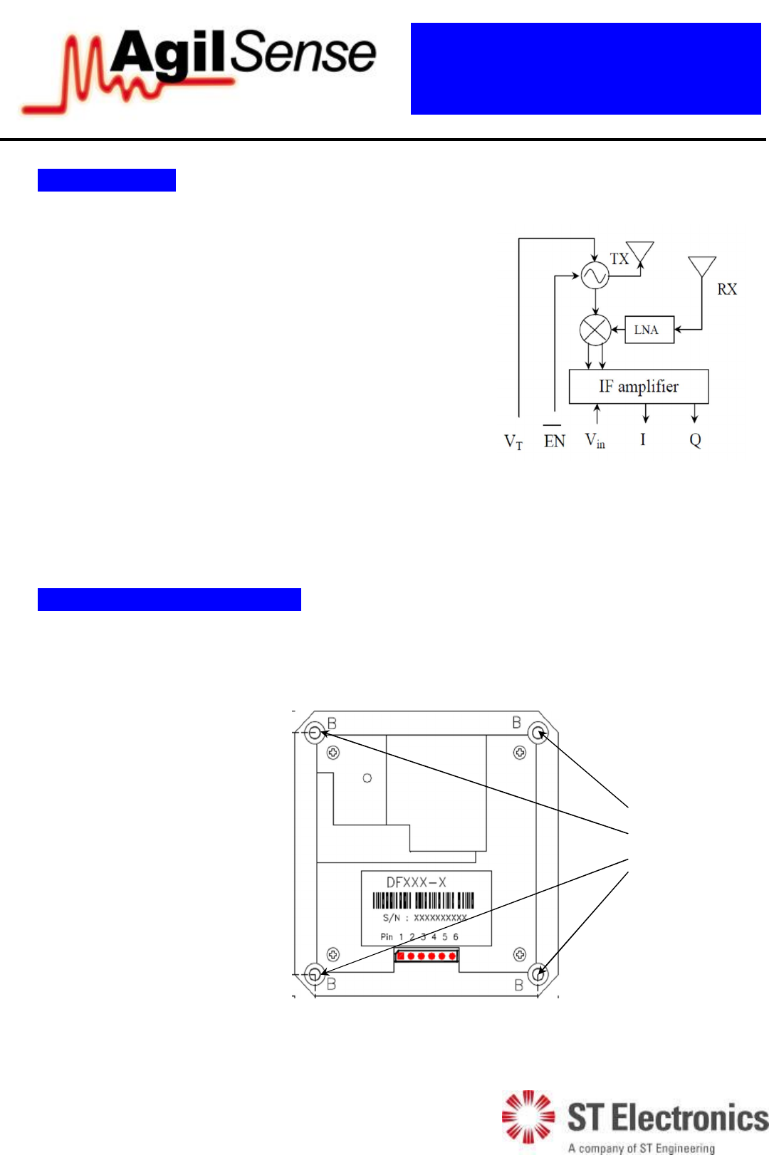
Figure 1: Block Diagram
The DF9 series (Frequency Modulated Continuous Wave)
microwave motion sensor modules are K-Band Bi-static
FMCW transceiver front-end modules. These modules are
designed for distance measurement, speed detection
together with direction of motion recognition. It is suitable
for intrusion detection and various traffic applications.
The module consists of Voltage controlled Oscillator
(VCO), balanced mixers; patch antenna, built-in LNA for
high sensitivity and a pre-amplifier (see Figure 1).
This Application Note highlights some important points for
application with DF9 series.
Pin definition
1: EN (Oscillator Enable)
2: Vin (Input Voltage)
3: GROUND (Ground)
4: I (IF Output)
5: Q (IF Output)
6: VT (Tuning Voltage)
Figure 2: Pin definition and mounting holes
Mounting
through holes
size M2.5.

2 of 16
MSAN
-
008
K-Band FMCW Transceiver DF Modules
Application Note
V1.0
1
ST Electronic
s (Satcom & Sensor Systems) Pte Ltd
1 Ang Mo Kio Electronics Park Road, #06-02, ST Engineering Hub, Singapore 567710
Tel: (65) 6521 7888 Fax: (65) 6521 7801 Email: info@agilsense.com
Website: www.agilsense.com ( Regn. No.: 199103901W )
3. Power Supply
For supply voltage, there is a built-in voltage regulation in the DF series transceivers. As such, the
performance of the DF9 seriesis not affected by variation of supply voltage as long as it is within the
specification. For example, performance of DF9 series will not be affected for any supply voltage from
3.6V to 9V. In this case, DF9 series is capable of being powered by standard voltage of 5V.
4. Transmitting frequency and EIRP
The transmitting EIRP (Effective Isotropic Radiated Power) of various modules are factory-set and are
not user-adjustable, while transmitting frequency is tunable and set by customer within given range.
Table 1 shows the EIRP and transmitting frequency ranges of some of the DF9 series modules.
Model EIRP Frequency Range
(FCC Part 15.245) Tuning voltage, VT
DF990 20 dBm 24.075 to 24.175 GHz 6V to 8V
DF995 17 dBm 24.075 to 24.175 GHz 6V to 8V
Table 1: Transmitting frequency for DF series
For most applications, the allowed operation frequency is between 24.075 to 24.175GHz for
compliance to FCC standard part 15.245. The user must ensure that the frequency used must be within
regulations of local communication authority by setting to the tuning voltage, VT specified in table 1.
Please refer to Annex 1 for more information on transmitting signal.
Local radio communication authority regulates the use of transmitting devices. Though user license
may be exempted, type approval of equipment or other regulation compliance may be required.
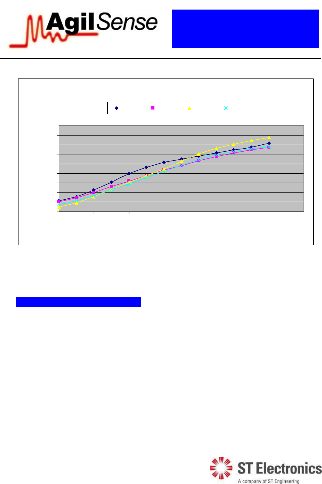
For DF9 series motion sensor, typical tunning slope is 30MHz per volt. Figure 3 shows the frequency
versus tuning voltage realtionship of 4 units of randomly selected DF990.
3 of 16
MSAN
-
008
K-Band FMCW Transceiver DF Modules
Application Note
V1.0
1
ST Electronic
s (Satcom & Sensor Systems) Pte Ltd
1 Ang Mo Kio Electronics Park Road, #06-02, ST Engineering Hub, Singapore 567710
Tel: (65) 6521 7888 Fax: (65) 6521 7801 Email: info@agilsense.com
Website: www.agilsense.com ( Regn. No.: 199103901W )
Frequency Vs Tuning Voltage
23.95
24
24.05
24.1
24.15
24.2
24.25
24.3
24.35
24.4
0 2 4 6 8 10 12 14
Tuning Voltage
Frequency
Unit 1 Unit 2 Unit 3 Unit 4
Figure 3: FMCW Tuning Slope
Calibration is highly recommended for every unit.
5. FMCW Application and Theory
Introduction
Unlike normal comtinuous wave sensor which transmits signal at a fixed frequency, the FMCW sensor
transmits freqency that are swept at a pre-determined pattern. Due to the time of flight associated with
the distance, there will be a frequency difference between transmitted signal and received reflected
signal. The resulting signal therefore provides information on:
Distance measurment
Velocity measuremnt
Direction of motion recognition
The following section explains the basic operation of FMCW sensor.
4 of 16
MSAN
-
008
K-Band FMCW Transceiver DF Modules
Application Note
V1.0
1
ST Electronic
s (Satcom & Sensor Systems) Pte Ltd
1 Ang Mo Kio Electronics Park Road, #06-02, ST Engineering Hub, Singapore 567710
Tel: (65) 6521 7888 Fax: (65) 6521 7801 Email: info@agilsense.com
Website: www.agilsense.com ( Regn. No.: 199103901W )
Stationary Object
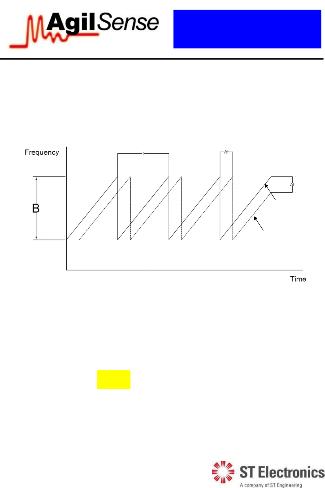
For stationary object, simple sawtooth shape frequency sweeping is suggested as there is no
requirements for measuring velocity. By varying tunning voltage , user will be able to obtain plot of
frequency versus time.
The solid line indicates transmitting signal while the dashed line indicates received signal from object.
As can be seen, there is a frequency difference f
between transmitted and received signal due to time
delay introduced by signal propagation in air.
Distance between sensor and detected object can be calculated based on formula:
k
fc
R
2
Where
R: Distance between sensor and object.
c: speed of light in freee space, 3*108m/s.
f
: frequency difference between sent and received signal.
k: gradient of frequency change.
Please refer to Annex 2 for more detailed FMCW stationary object range calculation.
Figure 4: Detection of Stationary Object
Received signal
Transmitted signal
5 of 16
MSAN
-
008
K-Band FMCW Transceiver DF Modules
Application Note
V1.0
1
ST Electronic
s (Satcom & Sensor Systems) Pte Ltd
1 Ang Mo Kio Electronics Park Road, #06-02, ST Engineering Hub, Singapore 567710
Tel: (65) 6521 7888 Fax: (65) 6521 7801 Email: info@agilsense.com
Website: www.agilsense.com ( Regn. No.: 199103901W )
Moving Object
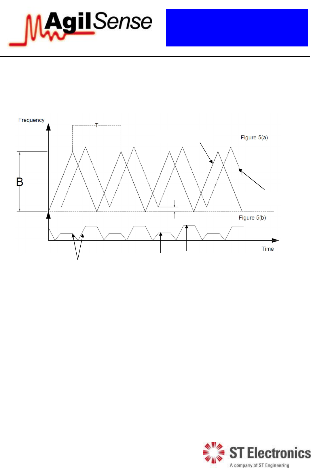
For detection of moving object, the triangle wave is suggested in order to obtain information on
distance and velocity ( Figure 5).
Figure 5: Detection of Moving Object
The solid line in figure 5(a) indicates transmitted signal while the dashed line indicates reflected
signal.The soild line in figure 5(b) stands for absolute value of frequency difference between
transmitted signal and received signal.
Note: Typically, computation of data takes place for period that generates stable fif+ and fif- ;
transition period is normally avoid.
By varying tuning voltage, user is suggested to increase frequency linearly from b
f(base frequency) to
Bf b (bandwidth) in half T (period) time and then decrease frequency linearly back to b
f in another
half T time. Compared to stationary object, moving object’s received signal not only has time delay
which introduces R
f, but also has upper or lower displacement due to the doppler frequency d
f.
Transition
Period
fif+
fif-
d
f Received signal
Transmitted signal

6 of 16
MSAN
-
008
K-Band FMCW Transceiver DF Modules
Application Note
V1.0
1
ST Electronic
s (Satcom & Sensor Systems) Pte Ltd
1 Ang Mo Kio Electronics Park Road, #06-02, ST Engineering Hub, Singapore 567710
Tel: (65) 6521 7888 Fax: (65) 6521 7801 Email: info@agilsense.com
Website: www.agilsense.com ( Regn. No.: 199103901W )
So, object’s distance R can be calculated based on this formula:
k
fc
RR
2
Where
2
ifif
R
ff
f
Object’s velocity v is given by:
0
2f
cf
vd
Where 0
fis the frequency of transmitted signal and
2
ifif
d
ff
f
Please refer to Annex 2 for more detailed FMCW moving object range and velocity calculation.
7 of 16
MSAN
-
008
K-Band FMCW Transceiver DF Modules
Application Note
V1.0
1
ST Electronic
s (Satcom & Sensor Systems) Pte Ltd
1 Ang Mo Kio Electronics Park Road, #06-02, ST Engineering Hub, Singapore 567710
Tel: (65) 6521 7888 Fax: (65) 6521 7801 Email: info@agilsense.com
Website: www.agilsense.com ( Regn. No.: 199103901W )
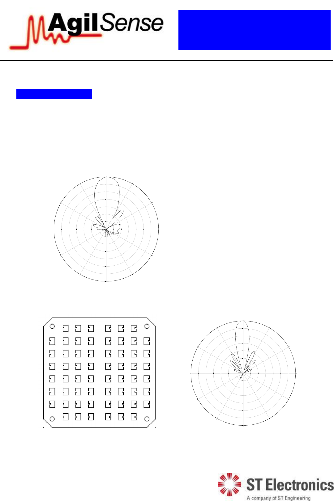
6. Radiation Pattern
The module to be mounted with the antenna patches facing to the desired detection zone. The user may
vary the orientation of the module to get the best coverage. The radiation patterns of the antenna and
their 3dB beam width are shown in below diagram.
E-plane
-35 -30 -25 -20 -15 -10 -5 0
-35
-30
-25
-20
-15
-10
-5
0
-35-30-25-20-15-10-50
-35
-30
-25
-20
-15
-10
-5
0
0
30
60
90
120
150
180
210
240
270
300
330
H-plane
-35 -30 -25 -20 -15 -10 -5 0
-35
-30
-25
-20
-15
-10
-5
0
-35-30-25-20-15-10-50
-35
-30
-25
-20
-15
-10
-5
0
0
30
60
90
120
150
180
210
240
270
300
330
Figure 6: Beam pattern of DF990
Elevation
Azimuth
8 of 16
MSAN
-
008
K-Band FMCW Transceiver DF Modules
Application Note
V1.0
1
ST Electronic
s (Satcom & Sensor Systems) Pte Ltd
1 Ang Mo Kio Electronics Park Road, #06-02, ST Engineering Hub, Singapore 567710
Tel: (65) 6521 7888 Fax: (65) 6521 7801 Email: info@agilsense.com
Website: www.agilsense.com ( Regn. No.: 199103901W )
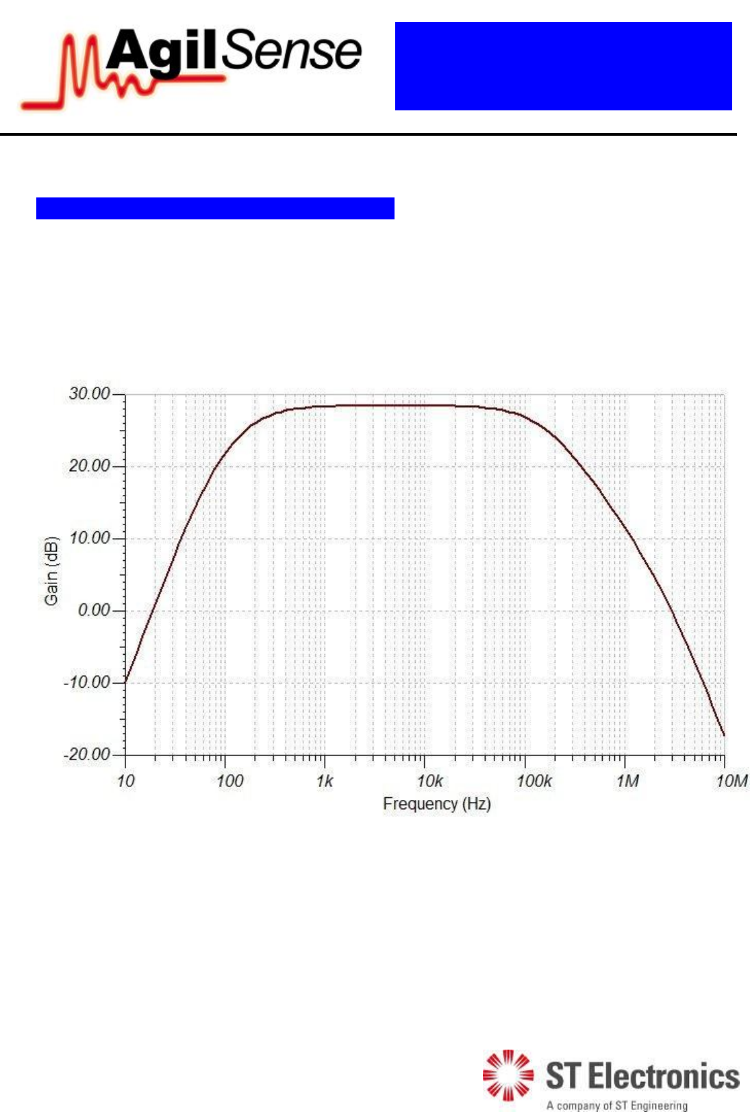
7. IF amplifier gain and frequency response
The DF9 series transceiver module comes with a built-in two-stage IF amplifier. The amplifier is
designed to provide low noise and hence, higher sensitivity. Besides, this amplifier acts as a buffer so
that the performance of the DF module is not affected by the loading at the IF output. A loading of at
least 1 k is recommended at the IF output.
Figure 7: Frequency response of IF amplifier of DF990
9 of 16
MSAN
-
008
K-Band FMCW Transceiver DF Modules
Application Note
V1.0
1
ST Electronic
s (Satcom & Sensor Systems) Pte Ltd
1 Ang Mo Kio Electronics Park Road, #06-02, ST Engineering Hub, Singapore 567710
Tel: (65) 6521 7888 Fax: (65) 6521 7801 Email: info@agilsense.com
Website: www.agilsense.com ( Regn. No.: 199103901W )
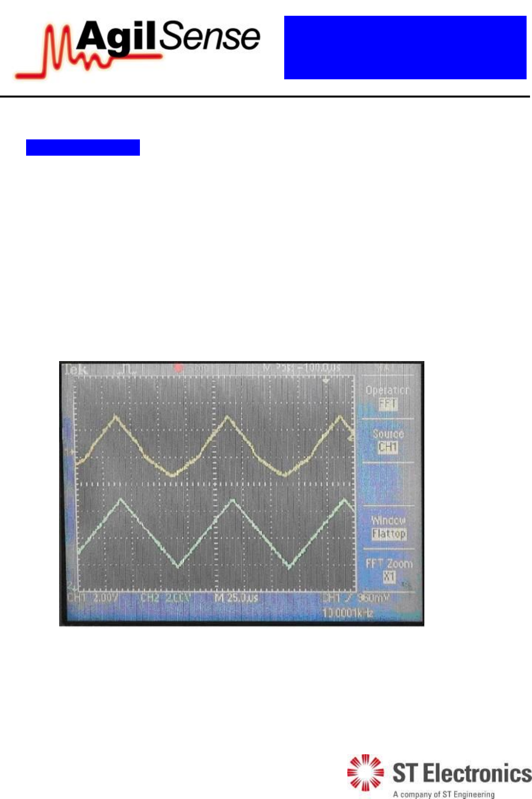
8. IF output signals
This section shows a typical signal at output from DF990 when pointed to the wall at certain distance.
This section means to serve as a guide.
Tuning Voltage Frequency: 10 KHz
Tuning Voltage Range; 1-6V
Sweeping Type; Triangle Function.
Figure 8 shows the signal at IF output when there is no target in the detection range of sensor.
Channel 2 (the blue line) indicates tuning voltage while Channel 1 (the yellow line) is the signal from Q
channel.
Figure 8: IF Output Signal and Input Tuning Voltage with no targets detected.
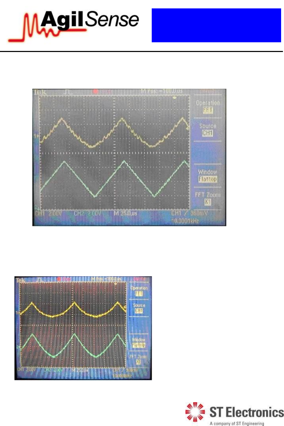
Figure 9 shows the signal at IF output when there is target in the detection range of sensor.
Channel 2 (the blue line) indicates tuning voltage while Channel 1 (the yellow line) shows the signal of
Q channel.
10 of 16
MSAN
-
008
K-Band FMCW Transceiver DF Modules
Application Note
V1.0
1
ST Electronic
s (Satcom & Sensor Systems) Pte Ltd
1 Ang Mo Kio Electronics Park Road, #06-02, ST Engineering Hub, Singapore 567710
Tel: (65) 6521 7888 Fax: (65) 6521 7801 Email: info@agilsense.com
Website: www.agilsense.com ( Regn. No.: 199103901W )
Figure 9: IF Output Signal and Input Tuning Voltage with target detected.
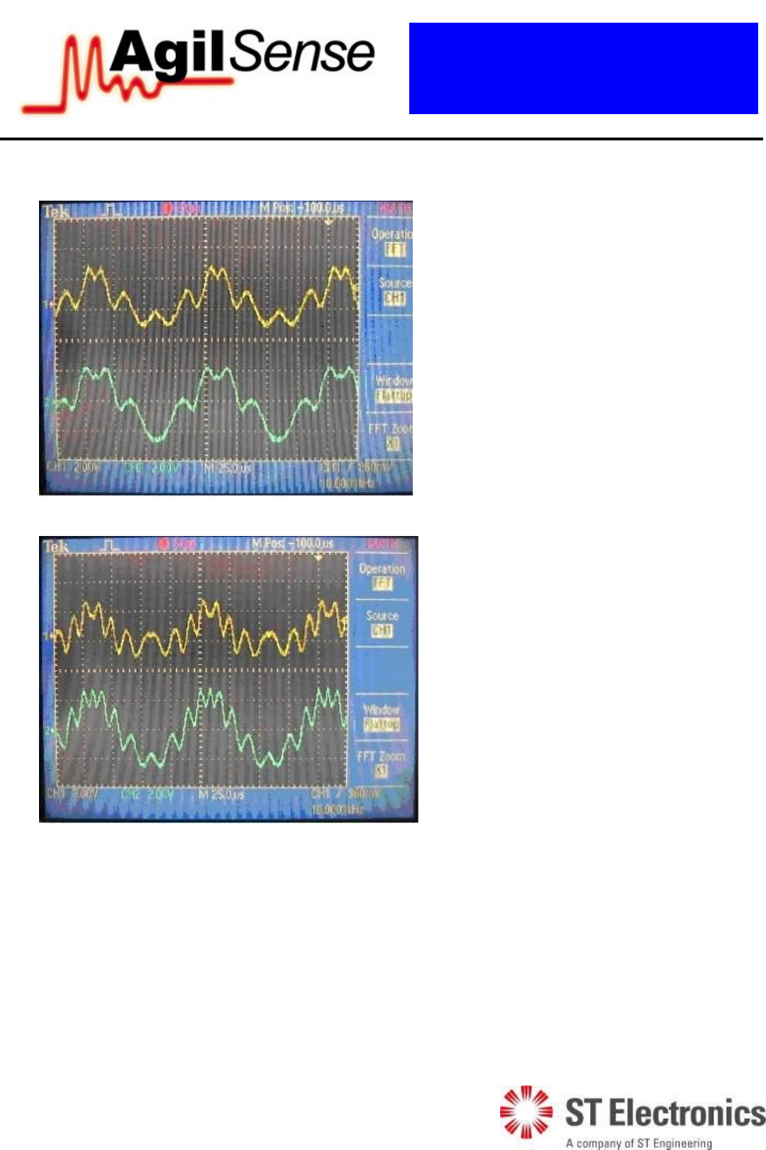
Figure 10 to 13 show the signals from IF output when targets at different distance are detected.
Figure 10: I and Q signal when no
target detected
11 of 16
MSAN
-
008
K-Band FMCW Transceiver DF Modules
Application Note
V1.0
1
ST Electronic
s (Satcom & Sensor Systems) Pte Ltd
1 Ang Mo Kio Electronics Park Road, #06-02, ST Engineering Hub, Singapore 567710
Tel: (65) 6521 7888 Fax: (65) 6521 7801 Email: info@agilsense.com
Website: www.agilsense.com ( Regn. No.: 199103901W )
Figure 11: I and Q sig
nal with target
detected at 1m away
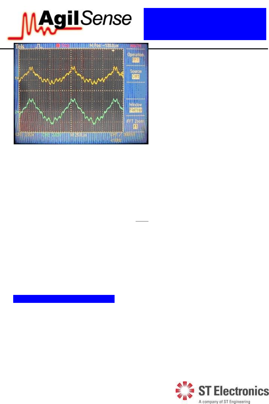
Figure 12: I and Q signal with target
detected at 3m away
12 of 16
MSAN
-
008
K-Band FMCW Transceiver DF Modules
Application Note
V1.0
1
ST Electronic
s (Satcom & Sensor Systems) Pte Ltd
1 Ang Mo Kio Electronics Park Road, #06-02, ST Engineering Hub, Singapore 567710
Tel: (65) 6521 7888 Fax: (65) 6521 7801 Email: info@agilsense.com
Website: www.agilsense.com ( Regn. No.: 199103901W )
There are two output signals in DF9 series: I and Q signal. As the figures shown, amplitude of output
signal becomes smaller when distance increases, while the frequency of output signal increases with
distance. When the distance of detected object is small enough, frequency difference of transmitted and
received signal will be equal or even less than sweeping frequency. In that case, user may not be able to
isolate frequency difference from sweeping frequency.
The minimum detection range for DF9 series will be:
B
c
R
2
Where
c: speed of light in freee space, 3*108m/s
B
: frequency sweeping bandwidth.
Reader may also notice the phase difference between I and Q signals. Ideally, there is a 90 degree phase
difference between I and Q signals. By identifying phase lagging/leading, information of movement
direction can be determined.
9. Placing the module in enclosure
As the applications of DF series are mostly in traffic (outdoor), it is inevitable that the module needs to
be housed in an enclosure. As such, it is important to ensure that the performance of the module is not
significantly degraded by the presence of enclosure.
The recommended material for the enclosure is plastic (such as ABS), as microwave can penetrate
through the material without significant loss. For comparison purpose, a metal results in full reflection
while water results in high absorption of the microwave. It is therefore important not to use any metallic
material as the enclosure.
Figure 13:
I and Q signal with target
detected at 5m away
13 of 16
MSAN
-
008
K-Band FMCW Transceiver DF Modules
Application Note
V1.0
1
ST Electronic
s (Satcom & Sensor Systems) Pte Ltd
1 Ang Mo Kio Electronics Park Road, #06-02, ST Engineering Hub, Singapore 567710
Tel: (65) 6521 7888 Fax: (65) 6521 7801 Email: info@agilsense.com
Website: www.agilsense.com ( Regn. No.: 199103901W )
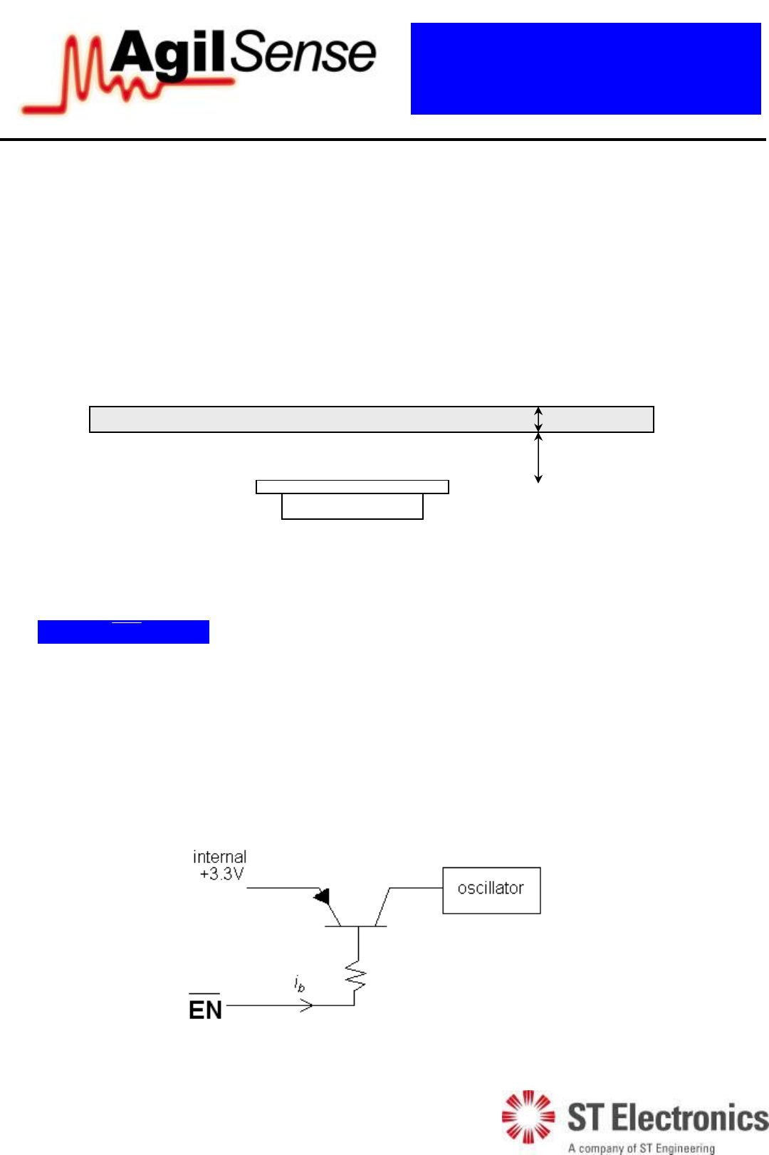
It is recommended that the cover placed in front of the DF antenna is of flat panel, so that the beam
width of the antenna is not significantly distorted. The thickness of the cover, h1 and the spacing between
the antenna and the cover, h2 should be ideally half-wavelength of the microwave signal.
In this case, for DF series module whose transmission frequency is ~24GHz, the recommended h1 and h2
are 3-4mm and 6mm.
A half wavelength of a 24 GHz in the air is about 6mm. However, the half wavelength of the signal in
other medium depends on the dielectric constant of the material. In the case of ABS which has a
dielectric constant of between 2.5 to 3.5, the half wavelength of the signal is 3 – 4 mm.
Figure 14: Recommended thickness and clearance for ABS placed in front of DF sensor
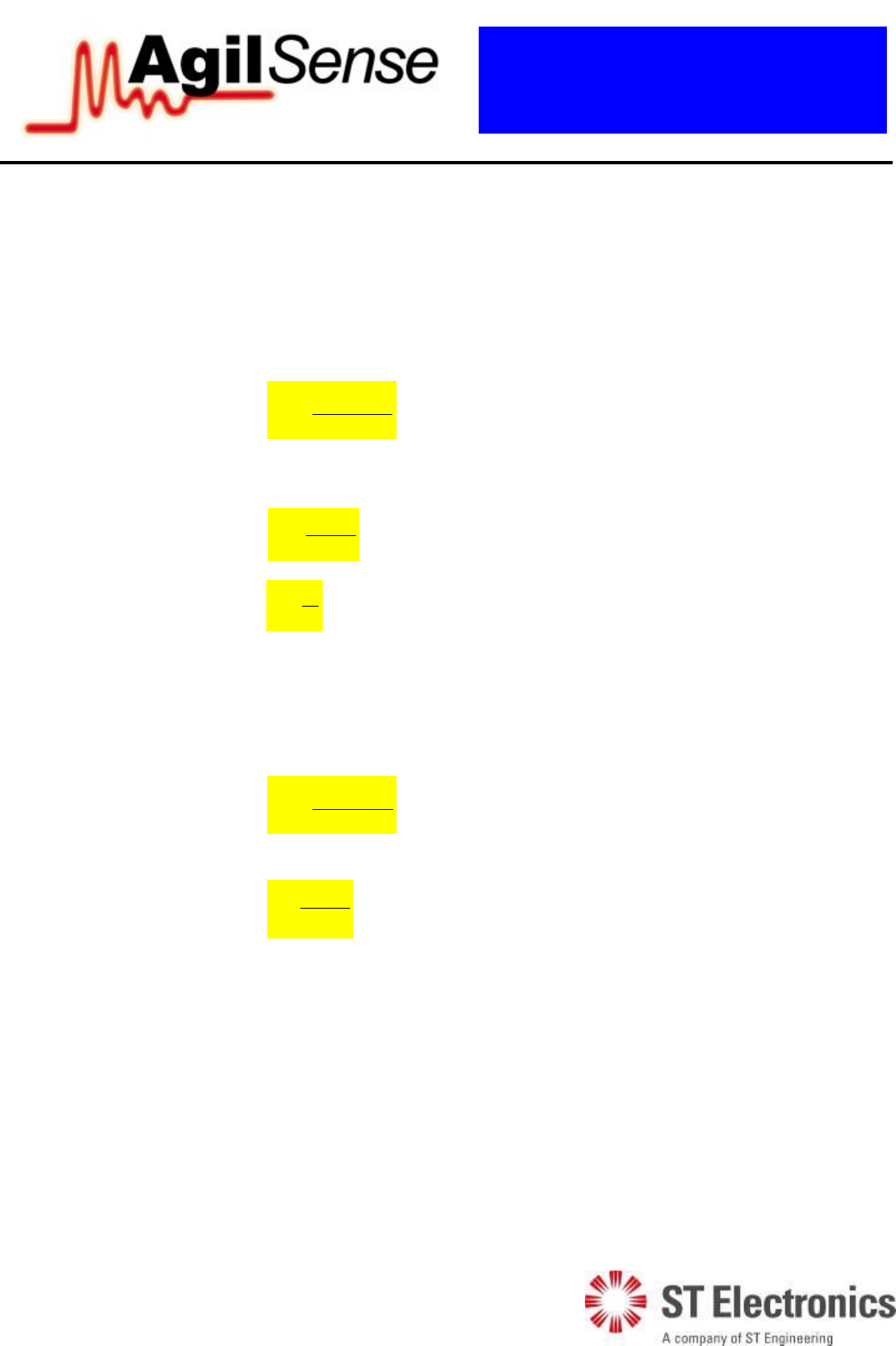
10. Using EN (pin 1)
EN (pin 1) can be used to control the oscillator. The internal voltage source is supplied to the oscillator
via a PNP transistor switch. When EN is asserted LOW (GND), the switch is on and internal voltage is
supplied to the oscillator, resulting in a transmission of 24GHz microwave signal. On the other hand,
when it is driven HIGH (+3.3V or higher), the oscillator is de-activated. The current drawn from the EN
pin is typically less than 1mA, and hence, it can be driven by TTL or CMOS as long as the voltage high
is +3.3V or more.
This feature can be used to reduce power consumption by introducing pulse to this pin.
Figure 15: Internal circuit of EN function in DF sensor
h
1
~ 3
-
4 mm
h2 ~ 6mm
ABS
DF unit

14 of 16
MSAN
-
008
K-Band FMCW Transceiver DF Modules
Application Note
V1.0
1
ST Electronic
s (Satcom & Sensor Systems) Pte Ltd
1 Ang Mo Kio Electronics Park Road, #06-02, ST Engineering Hub, Singapore 567710
Tel: (65) 6521 7888 Fax: (65) 6521 7801 Email: info@agilsense.com
Website: www.agilsense.com ( Regn. No.: 199103901W )
12. Radiation Safety
Microwave radiation from the module is well below established safety standards for general public
environment, like ANSI C95.1-1991 of USA and NRPB-G11 of United Kingdom.
13. Handling
The module has been fully tested to specifications. Opening, tightening or loosening the chassis may
result in performance deterioration.
The module is an electrostatic sensitive device (ESD). Precautions shall be observed for handling and
assembly.
14. Product Support
Please contact our product support engineers in the factory for technical assistance whenever necessary.
Product Support (Microwave Sensors)
Tel: (65) 6521 7888
Fax: (65) 6521 7801
E-mail: info@agilsense.com
This device complies with part 15 of FCC Rules.
Operation is subject to the following two conditions: (1) This device may not cause harmful interference, and
(2) this device must accept any interference received, including interference that may cause undesired
operation.
Any changes or modifications to ST Electronics equipment not expressly approved by ST Electronics could
void the user authority to operate the equipment.
The system integrated the radio should have label indicated the FCC ID of approved Radio.
Such as putting a label on system as below: CONTAIN FCC ID: VECDF990
Warning : The radio does not allow to be installed and operated with other radio simultaneously when
integrated in host system.
Installed in such configuration may subject to additional FCC testing and equipment authorization.

15 of 16
MSAN
-
008
K-Band FMCW Transceiver DF Modules
Application Note
V1.0
1
ST Electronic
s (Satcom & Sensor Systems) Pte Ltd
1 Ang Mo Kio Electronics Park Road, #06-02, ST Engineering Hub, Singapore 567710
Tel: (65) 6521 7888 Fax: (65) 6521 7801 Email: info@agilsense.com
Website: www.agilsense.com ( Regn. No.: 199103901W )
Annex 1: Transmission of RF
1. Though same frequency is allocated in some countries, national regulations may specify different
EIRP, spurious emission or other requirements.
2. The DF990 model is designed to meet the FCC standard part 15.245 and is aimed for use in the
America.
3. The regulations are subjected to change from time to time, please contact appropriate authorities for
full and up-to-dated information.
4. Useful websites:
Agency Website
The Code of Federal Regulations, USA http://www.access.gpo.gov/cgi-
bin/cfrassemble.cgi?title=199847
Federal Communications Commission http://www.fcc.gov/
Annex 2: FMCW Theory
Stationary Object
The relation between distance and frequency difference is:
k
c
R
ktf
2
Where
R: Distance between sensor and object.
c: speed of light in freee space, 3*108m/s
t
: measured time difference
k: gradient of frequency change.
Where k
T
B
T: frequency sweeping period of sensor
B
: frequency sweeping bandwidth.
So, distance is given by:
k
fc
R
2
16 of 16
MSAN
-
008
K-Band FMCW Transceiver DF Modules
Application Note
V1.0
1
ST Electronic
s (Satcom & Sensor Systems) Pte Ltd
1 Ang Mo Kio Electronics Park Road, #06-02, ST Engineering Hub, Singapore 567710
Tel: (65) 6521 7888 Fax: (65) 6521 7801 Email: info@agilsense.com
Website: www.agilsense.com ( Regn. No.: 199103901W )
Moving Object
Due to the existence of doppler frequnency in the if
fand if
f, the frequency associated to range is given
by:
2
ifif
R
ff
f
Hence, object’s distance is given by:
k
fc
RR
2
Where k
T
B
T: frequency sweeping period of sensor
B
: frequency sweeping bandwidth.
From the graph, the doppler frequency d
fcan be obtained by the following:
2
ifif
d
ff
f
The relationship between doppler frequency and velocity is given by:
0
2f
cf
vd
Where
v: velocity of the moving object
0
f: frequency of transmitted signal
c: speed of light in freee space, 3*108m/s
Note: based on the phase of two channels’ output, moving direction of object can be identified.