ST Engineering Telematics Wireless
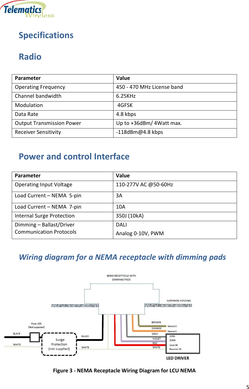
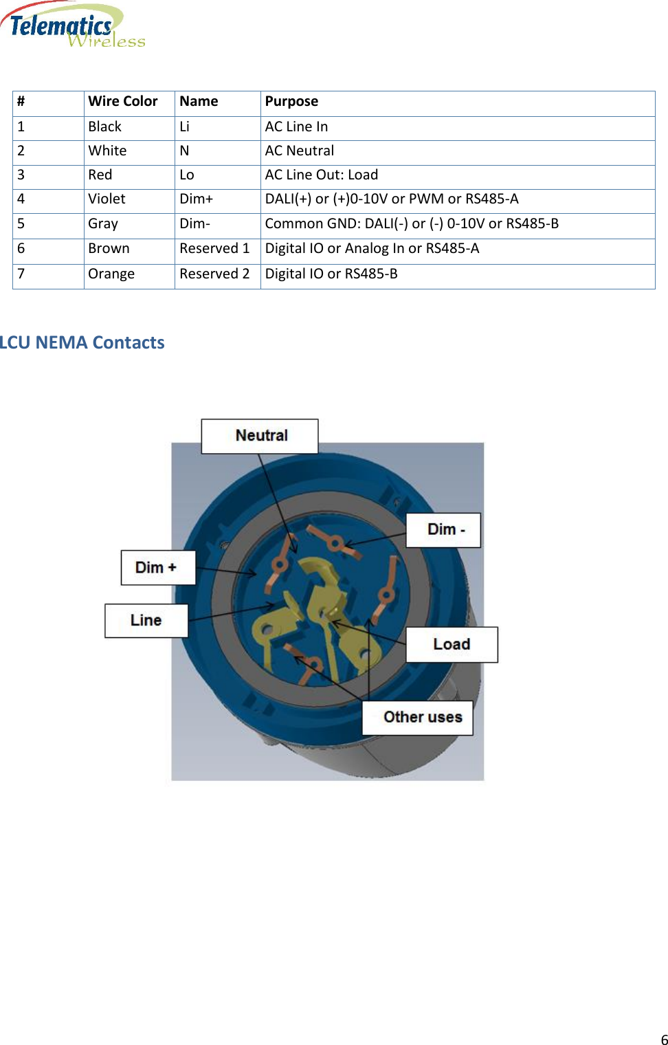
 LCUN2G1 LCU NEMA User Manual DCU2 E Installation Manual v1 1

Telematics Wireless Ltd. LCU NEMA DCU2 E Installation Manual v1 1

Users Manual

 T-LightTM LCU (Light Control Unit) NEMA User Manual Model: LCUN2GUS  Revision 1.02, June 21, 2016 Copyright © Telematics Wireless Ltd. All rights reserved The  document  contains  proprietary  information  of  Telematics  Wireless,  Ltd.;  it  is  provided  under  a  license  agreement containing restrictions on use and disclosure, and is also protected by copyright law. Due to continued product development this information may change without notice. The information and intellectual property contained  herein  is  confidential  between  Telematics  Wireless  Ltd.  and  the  client,  and  remains  the  exclusive  property  of Telematics Wireless Ltd.  If  you find any  problems  in the documentation,  please report them to us in writing.  Telematics Wireless Ltd. does not warrant that this document is error-free. No  part  of  this  publication  may  be  reproduced,  stored  in  a  retrieval  system,  or  transmitted  in  any  form  or  by  any  means, electronic, mechanical, photocopying, recording, or otherwise without the prior written permission  of  Telematics Wireless Ltd.
     2  Contents About Telematics Wireless Products ................................................................................................... 3 LCU NEMA Description .............................................................................................................................. 3 Standard Features .................................................................................................................................. 4 Optional Features .................................................................................................................................. 4 Specifications ..................................................................................................................................... 5 Power and control Interface ............................................................................................................... 5 Wiring diagram for a NEMA receptacle with dimming pads ................................................................ 5 LCU NEMA Contacts ............................................................................................................................... 6 LCU NEMA Pin Options .......................................................................................................................... 7 Physical Specifications ....................................................................................................................... 8 Environment ...................................................................................................................................... 8 Standards Compliance ................................................................................................................................... 8 Regulation Information ...................................................................................................................... 9 Installation Requirements ................................................................................................................ 11 Mandatory Customer-Supplied Equipment............................................................................................. 11 Location  Post-Installation Commissioning ............................................................................................................. 11 Contact Details ................................................................................................................................ 12  List of Figures Figure 1 – System Topology .......................................................................................................................... 3 Figure 1 -  NEMA Receptacle Wiring Diagram for LCU NEMA …………………………………………………………....……5
     3  About Telematics Wireless Products Telematics Wireless products  have  been  evaluated as Information Technology Equipment (ITE), which may  be  installed in Central Offices, Telecommunication  Centers,  offices,  computer rooms,  and  similar commercial-type indoor or outdoor locations. Telematics  Wireless  is  an  Associate  Member  of  the  TALQ  Consortium,  and  its  products  are  ELEXON-approved.                                                                      LCU NEMA Description LCU NEMA is a luminaire control unit, easily installed on top of the luminaire utilizing a standard  (twist and lock) NEMA socket. LCU NEMA is a unit of  the T-Light Galaxy star network. Control features offer On/Off  and  dimming  level  operations.  Monitoring  features  include  identification  of  lamp  and measurement  of  electrical  parameters.  The  LCU  NEMA  is  controlled  by  the  Smart  Lighting  System Control Management Software (CMS) via a Data Communication Unit (DCU) gateway.     Figure 2 – System Topology
     4  Standard Features  Light sensor - Operates as a photocell with the integrated microcontroller and is used as a backup light control in the event of microcontroller failure.  Energy meter - Continuous measurement collection and aggregation with 1% accuracy.  Integrated RF antenna.  Over the air firmware updates.  Each unit is configurable as a repeater, resulting in one additional ‘hop’ from the DCU.  Real Time Clock.  Network data is protected by AES 128 encryption and, optionally, AES 256.  Relay Control for LED driver/ballast power.  Alarms for power extremes and maximum temperature.  “Auto Detection and Verification” Software “Auto Detection and Verification” Software The LCU NEMA includes the Telematics  “Auto Detection and Verification” software that automatically detects and stores the ballast type (1-10V or DALI) in the LCU. The ballast type is then retrieved during the commissioning process, thereby eliminating the need to enter it manually into the CMS. Optional Features  Built-in GPS receiver for full auto-commissioning.  Built-in NFC chip for data exchange with hand-held device.         LCU NEMA
     5  Specifications Radio Power and control Interface Parameter Value Operating Input Voltage 110-277V AC @50-60Hz  Load Current – NEMA  5-pin 3A Load Current – NEMA  7-pin 10A Internal Surge Protection 350J (10kA) Dimming – Ballast/Driver Communication Protocols DALI Analog 0-10V, PWM Wiring diagram for a NEMA receptacle with dimming pads  Figure 3 - NEMA Receptacle Wiring Diagram for LCU NEMA Parameter Value Operating Frequency 450 - 470 MHz License band Channel bandwidth 6.25KHz Modulation  4GFSK Data Rate 4.8 kbps Output Transmission Power  Up to +36dBm/ 4Watt max. Receiver Sensitivity  -118dBm@4.8 kbps
     6   LCU NEMA Contacts      # Wire Color Name Purpose 1 Black Li  AC Line In 2 White N AC Neutral 3 Red Lo AC Line Out: Load 4 Violet Dim+ DALI(+) or (+)0-10V or PWM or RS485-A 5 Gray Dim- Common GND: DALI(-) or (-) 0-10V or RS485-B 6 Brown Reserved 1 Digital IO or Analog In or RS485-A 7 Orange Reserved 2 Digital IO or RS485-B
     7     LCU NEMA Pin Options    # Wire Color Name Purpose 1 Black Li  AC Line In 2 White N AC Neutral 3 Red Lo AC Line Out: Load 4 Violet Dim+ DALI(+) or (+)0-10V or PWM or RS485-A 5 Gray Dim- Common GND: DALI(-) or (-) 0-10V or RS485-B 6 Brown Reserved 1 Digital IO or Analog In or RS485-A 7 Orange Reserved 2 Digital IO or RS485-B                     LED Driver  Model Pin 1-2 Black-White Pins 3-2 Red-White Pins 5-4 Gray-Violet Pins 6-7 Brown-Orange External NEMA 5-pin – Standard Main AC Line IN Main AC Neutral IN AC for lamp Line OUT Neutral IN Dimming – 0-10V Analog, DALI, PWM, Modbus RS485 N/A External NEMA 7-pin - Optional Main AC Line IN Main AC Neutral IN AC for lamp Line OUT Neutral IN Dimming – 0-10V Analog, DALI, PWM, Modbus RS485  For user purposes, for example, sensors, Modbus RS485, GPIO-digital or analog
     8  Physical Specifications Parameter Value Dimension 3.467 in D x 4.173 in H (88 mm D x 106 mm H) Weight  225 g Environment  Operation Temperature -40 F to 161.6 F (-40 C to +72 C) IP Rating IP 66 per IEC 60529-1  Standards Compliance   Radio USA FCC 47CFR part 90 (mask E)  Canada RSS 119 Europe ETSI EN 300-113-2 EMC USA FCC 47CFR part 15 subpart B  Canada ICES-003 Europe EN 301-489-1, EN 301-489-3 Safety USA UL 916 Canada CSA C22.2 NO. 205. Europe IEC 61347-2-11:2001 (IEC 61347-1:2007)
     9    Regulation Information FCC Part 15 Regulation Class B device The digital circuit of this device has been tested and found to comply with the limits for a Class B digital  device,  pursuant  to  part  90  of  the  FCC  Rules.  These  limits  are  designed  to  provide reasonable protection against harmful interference in a residential installation. This equipment generates  uses  and  can  radiate  radio  frequency  energy  and,  if  not  installed  and  used  in accordance  with  the  instructions,  may  cause  harmful  interference  to  radio  communications. However, there is no guarantee that interference will not occur in a particular installation. If this equipment  does  cause  harmful  interference  to  radio  or  television  reception,  which  can  be determined by turning the equipment off and on, the user is encouraged to try to correct the interference by one or more of the following measures: -Reorient or relocate the receiving antenna. -Increase the separation between the equipment and receiver. -Connect the equipment into an outlet on a circuit different from that to which the receiver is connected. -Consult the dealer or an experienced radio/TV technician for help.  Industry Canada Class B Notice This  device  complies  with  Industry  Canada’s  licence-exempt  RSSs.  Operation  is  subject  to  the following two conditions: (1) This device may not cause interference; and (2) This device must accept any interference, including interference that may cause undesired operation of the device. Le  présent  appareil  est  conforme  aux  CNR  d’Industrie  Canada  applicables  aux  appareils  radio exempts de licence. L’exploitation est autorisée aux deux conditions suivantes :  (1) l’appareil ne doit pas produire de brouillage;  (2)  l’utilisateur  de  l’appareil  doit  accepter  tout  brouillage  radioélectrique  subi,  même  si  le brouillage est susceptible d’en compromettre le fonctionnement.  CAN ICES-3 (B)/NMB-3(B) This Class B digital apparatus complies with Canadian ICES-003. Cet appareil numerique de la classe B est conforme a la norme NMB-003 du Canada.
     10   FCC interference Notice This  device  complies  with  part  90  of  the  FCC  rules.  Operation  is  subject  to  the  following  two conditions: (1) This device may not cause interference; and (2) This device must accept any interference, including interference that may cause undesired operation of the device.   FCC and Industry Canada Radiation Hazard Warning The antenna used for this transmitter must be installed to normally provide minimum separation distance of at least 20 cm from all persons.  Le  dispositif  doit  être  placé  à  une  distance  d'au  moins  20  cm  à  partir  de  toutes  les personnes  au  cours  de  son  fonctionnement  normal.  Les  antennes  utilisées  pour  ce produit ne doivent pas être situés ou exploités conjointement avec une autre antenne ou transmetteur.
     11  Installation Requirements Mandatory Customer-Supplied Equipment  System  integrity  for  the  LCU  NEMA  is  ensured  with  the  mandatory  installation  of  customer-supplied voltage and current surge protection equipment. Mandatory Voltage Surge Protection  Warning: To prevent damage due to power network voltage surges, it is mandatory that you also provide and install a surge protection device to protect the LCU and the luminaire driver. Mandatory Current Surge Protection  Warning: To prevent damage due to power network current surges, it is mandatory that you also provide and install a 10 amp slow-blow fuse or circuit breaker to protect the LCU and the luminaire driver. Location The LCU NEMA is installed on the top surface of the luminaire cover utilizing a standard  (twist and lock) NEMA socket.  Post-Installation Commissioning In  order  for  the  installed  LCU  NEMA  units  to  be  recognized  in  the  Telematics  Wireless  Smart Lighting System, the serial numbers and GPS coordinates of the LCU NEMA units must be added to the CMS Equipment Inventory as part of the commissioning process. The level of automation in the Commissioning process depends on the optional equipment installed in the LCU NEMA:  GPS  –  Commissioning  is  fully  automated.  Commissioning  is  complete  after  the  CMS Administrator executes the relevant command.  NFC –  Commissioning is partially automated. The required serial number  and GPS coordinates are  obtained  at  the  installation  site  with  an  Android  smartphone  and  a  Telematics  app. Commissioning is complete after the CMS Administrator executes the relevant command.  No GPS or NFC – Commissioning is a partially manual process:
     12  ◦ Installer obtains the GPS coordinates of the LCU NEMA with a handheld GPS device. ◦ Installer records the serial number and GPS coordinates. ◦ CMS Administrator imports the recorded values into the CMS Equipment Inventory, one by one or by batch. Contact Details Contact your local Telematics technical support representative, or contact us at: Telematics Wireless, Ltd. 26 Hamelacha St., POB 1911 Holon 58117 ISRAEL Phone: +972-3-557-5763 Fax: +972-3-557-5703 Sales: sales@tlmw.com Support: support@tlmw.com www.telematics-wireless.com

Navigation menu