ST Engineering Telematics Wireless LCUN2P1 LCU NEMA User Manual DCU2 E Installation Manual v1 1
Telematics Wireless Ltd. LCU NEMA DCU2 E Installation Manual v1 1
User Manual

T-LightTM LCU (Light Control Unit) NEMA
User Manual
Model: LCUN2PUS (North America)
Model: LCUN2PAU (Australia/NZ)
Revision 1.02, June 21, 2016
Copyright © Telematics Wireless Ltd.
All rights reserved
The document contains proprietary information of Telematics Wireless, Ltd.; it is provided under a license agreement
containing restrictions on use and disclosure, and is also protected by copyright law.
Due to continued product development this information may change without notice. The information and intellectual property
contained herein is confidential between Telematics Wireless Ltd. and the client, and remains the exclusive property of
Telematics Wireless Ltd. If you find any problems in the documentation, please report them to us in writing. Telematics
Wireless Ltd. does not warrant that this document is error-free.
No part of this publication may be reproduced, stored in a retrieval system, or transmitted in any form or by any means,
electronic, mechanical, photocopying, recording, or otherwise without the prior written permission of Telematics Wireless
Ltd.

2
Contents
1. About Telematics Wireless Products ....................................................................................... 3
1.1. T-Light LCU Product Description .................................................................................................. 3
1.2. Functionality ................................................................................................................................ 4
1.3. Reports ......................................................................................................................................... 4
2. Specifications ......................................................................................................................... 5
Power and control Interface ................................................................................................... 5
Wiring diagram for a NEMA receptacle with dimming pads .................................................... 5
Physical Specifications ........................................................................................................... 7
Environment .......................................................................................................................... 7
Standards Compliance ................................................................................................................. 7
3. Regulation Information .......................................................................................................... 8
FCC Part 15 Regulation Class B device ..................................................................................... 8
4. Installation Requirements .................................................................................................... 10
4.1. Mandatory Customer-Supplied Equipment ............................................................................... 10
4.2. Location ..................................................................................................................................... 10
4.3. Post-Installation Commissioning ............................................................................................... 10
5. Contact Details .................................................................................................................... 11
List of Figures
Figure 1 - T-Light Pro Topology ..................................................................................................................... 3
Figure 1 - NEMA Receptacle Wiring Diagram for LCU NEMA……………………………………………………………………5
3
1. About Telematics Wireless Products
Telematics Wireless products have been evaluated as Information Technology Equipment (ITE), which
may be installed in Central Offices, Telecommunication Centers, offices, computer rooms, and similar
commercial-type indoor or outdoor locations.
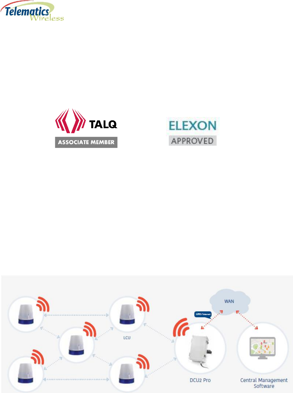
Telematics Wireless is an Associate Member of the TALQ Consortium, and its products are ELEXON-
approved.
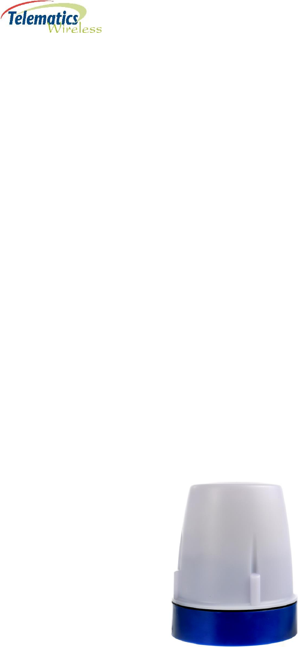
1.1. LCU NEMA Product Description
LCU NEMA is a luminaire control unit, easily installed on top of the luminaire utilizing a standard (twist
and lock) NEMA socket. LCU NEMA is a principal component of the T-Light street light control Pro mesh
network. The LCU NEMA controls its LED driver or electronic ballast to provide On/Off and dimming
functionality. The LCU NEMA provides various comprehensive energy measurements, luminaire
parameters and maintenances statuses.
The LCU NEMA units receive commands individually or as a group from the Data Control Unit (DCU)
gateway; commands can be changed as and when needed. The T-Light network is easily controlled
either automatically through the web-accessed T-Light CMS system (or a 3rd party management
software).
Figure 2 - T-Light Pro Topology
4
1.2. Functionality
• On/Off and dimming functionality using automatic DALI/ 0-10 volt selection
• Luminaire power consumption measurement to 1% accuracy
• Analog and digital input for interfacing with external sensors
• Auto-commissioning with GPS or NFC chip
• Internal or external configurations
• Highly secure wireless communication utilizing AES-128 or AES- 256
• Enclosures - NEMA: ANSI C136.41, 7pin
• Dual backup protection – autonomous operation based on a pre-programmed scenario; built in light,
no dayburn
• Supports over the air firmware upgrade
• Data and settings preserved in case of power failure
• LCU NEMA stores history of measured parameters for at least a week to allow for data extraction
• Controlled Auxiliary Output (optional)
• Includes the Telematics “Auto Detection and Verification” software that automatically detects and
stores the ballast type (1-10V or DALI) in the LCU NEMA. The ballast type is then retrieved during the
commissioning process, thereby eliminating the need to enter it manually into the CMS.
1.3. Reports
• Reports of events related to exceeding established parameter limits
• Aggregate energy and active power consumption
• Burning hours
• Number of On/Off cycles
• Failure reports
• Various luminaire dynamic parameters such as: instantaneous levels of ambient light, power
consumption, voltage, current, power factor, temperature.
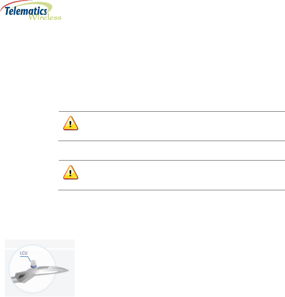
LCU NEMA
5
2. Specifications
Radio
Power and control Interface
Parameter
Value
Operating Input Voltage
110-277V AC @50-60Hz
Load Current – NEMA 5-pin
3A
Load Current – NEMA 7-pin
10A
Dimming – Ballast/Driver
Communication Protocols
DALI
Analog 0-10V, PWM
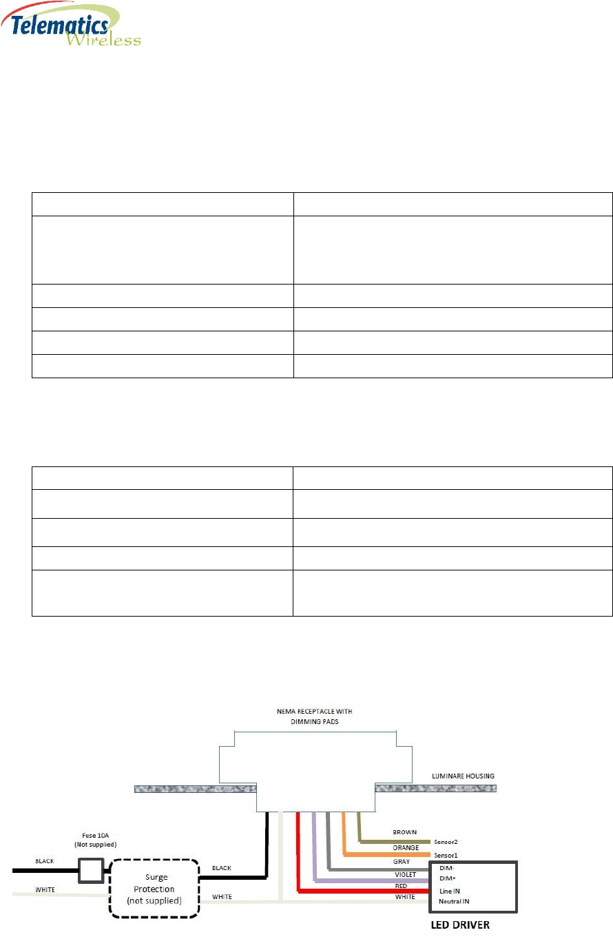
Wiring diagram for a NEMA receptacle with dimming pads
Figure 3 - NEMA Receptacle Wiring Diagram for LCU NEMA
Parameter
Value
Operating Frequency
902MHz – 928MHz US ISM band (North America)
869.5MHz (Europe)
915-928MHz band (Australia/NZ)
Data Rate
110 kbps
Modulation
2GFSK
Receiver Sensitivity
-102dBm@110kbps
Output Transmission Power
Up to +27dBm/ 500 mW max

6
NEMA Contacts
#
Wire Color
Name
Purpose
1
Black
Li
AC Line In
2
White
N
AC Neutral
3
Red
Lo
AC Line Out: Load
4
Violet
Dim+
DALI(+) or (+)0-10V or PWM or RS485-A
5
Gray
Dim-
Common GND: DALI(-) or (-) 0-10V or RS485-B
6
Brown
Reserved
1
Digital IO or Analog In or RS485-A
7
Orange
Reserved
2
Digital IO or RS485-B
7
Physical Specifications
Parameter
Value
Dimension
3.467 in D x 4.173 in H
(88 mm D x 106 mm H)
Weight
225 g
Environment
Operation Temperature
-40 F to 161.6 F
(-40 C to +72 C)
IP Rating
IP 66 per IEC 60529-1
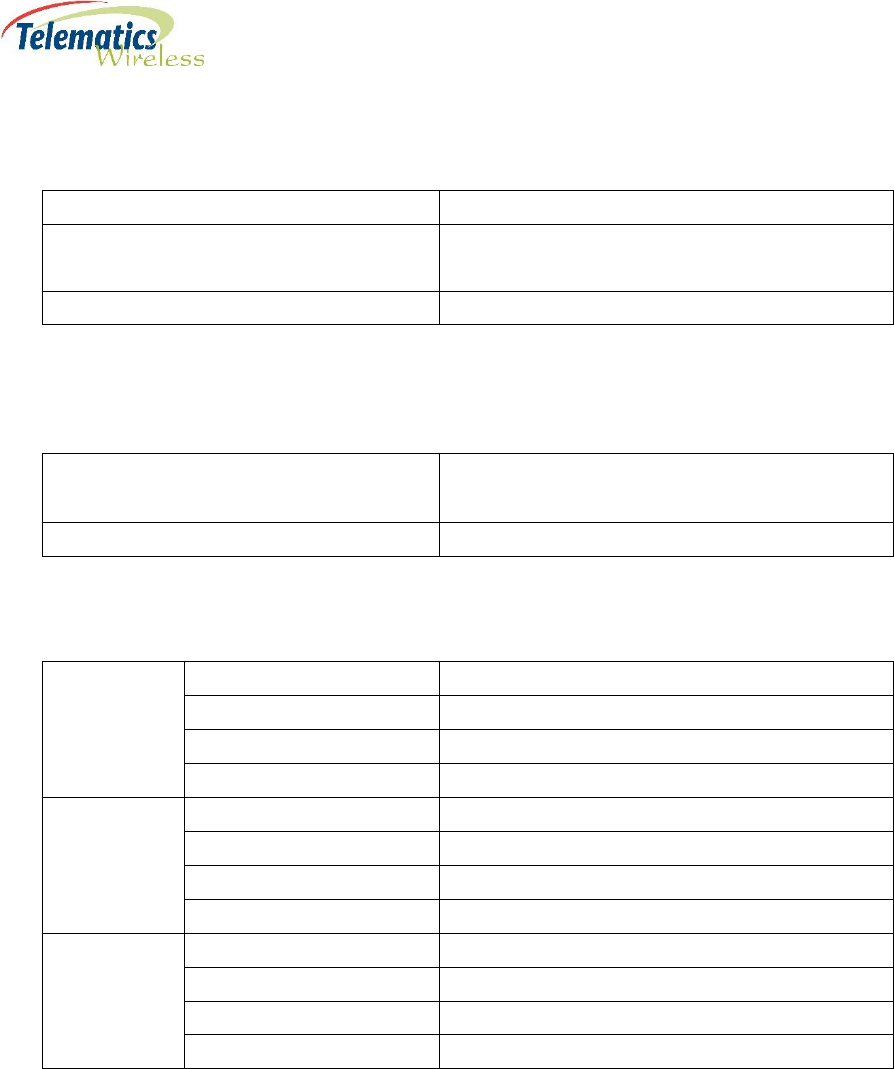
Standards Compliance
Radio
USA
FCC 47CFR part 15 subpart C
Canada
RSS 247
Australia/NZ
AS/NZS 4268
Europe
EN 300-220-2
EMC
USA
FCC 47CFR part 15 subpart B
Canada
ICES-003
Australia/NZ
AS/NZS CISPR 22, class B
Europe
EN 301-489-1, EN 301-489-3
Safety
USA
UL 773A
Canada
CSA C22.2 NO. 182.2.
Australia/NZ
AS/NZS 60950.1
Europe
EN 61347-1, EN 61347-2-11

8
3. Regulation Information
FCC Part 15 Regulation Class B device
The digital circuit of this device has been tested and found to comply with the limits for a Class B
digital device, pursuant to part 15 of the FCC Rules. These limits are designed to provide
reasonable protection against harmful interference in a residential installation. This equipment
generates uses and can radiate radio frequency energy and, if not installed and used in
accordance with the instructions, may cause harmful interference to radio communications.
However, there is no guarantee that interference will not occur in a particular installation. If this
equipment does cause harmful interference to radio or television reception, which can be
determined by turning the equipment off and on, the user is encouraged to try to correct the
interference by one or more of the following measures:
-Reorient or relocate the receiving antenna.
-Increase the separation between the equipment and receiver.
-Connect the equipment into an outlet on a circuit different from that to which the receiver
is connected.
-Consult the dealer or an experienced radio/TV technician for help.
Industry Canada Class B Notice
This device complies with Industry Canada’s licence-exempt RSSs. Operation is subject to the
following two conditions:
(1) This device may not cause interference; and
(2) This device must accept any interference, including interference that may cause undesired
operation of the device.
Le présent appareil est conforme aux CNR d’Industrie Canada applicables aux appareils radio
exempts de licence. L’exploitation est autorisée aux deux conditions suivantes :
(1) l’appareil ne doit pas produire de brouillage;
(2) l’utilisateur de l’appareil doit accepter tout brouillage radioélectrique subi, même si le
brouillage est susceptible d’en compromettre le fonctionnement.
FCC interference Notice
This device complies with part 15 of the FCC rules. Operation is subject to the following two
conditions:
(1) This device may not cause interference; and
(2) This device must accept any interference, including interference that may cause undesired
operation of the device.

9
FCC and Industry Canada Radiation Hazard Warning
The antenna used for this transmitter must be installed to normally provide minimum
separation distance of at least 20 cm from all persons.
Le dispositif doit être placé à une distance d'au moins 20 cm à partir de toutes les
personnes au cours de son fonctionnement normal. Les antennes utilisées pour ce
produit ne doivent pas être situés ou exploités conjointement avec une autre antenne
ou transmetteur.
10
4. Installation Requirements
4.1. Mandatory Customer-Supplied Equipment
System integrity for the LCU NEMA is ensured with the mandatory installation of customer-supplied
voltage and current surge protection equipment.
Mandatory Voltage Surge Protection
Warning: To prevent damage due to power network voltage surges, it is
mandatory that you also provide and install a surge protection device to protect
the LCU and the luminaire driver.
Mandatory Current Surge Protection
Warning: To prevent damage due to power network current surges, it is
mandatory that you also provide and install a 10 amp slow-blow fuse or circuit
breaker to protect the LCU and the luminaire driver.
4.2. Location
The LCU NEMA is installed on the top surface of the luminaire cover utilizing a standard (twist and lock)
NEMA socket.
4.3. Post-Installation Commissioning
In order for the installed LCU NEMA units to be recognized in the Telematics Wireless Smart Lighting
System, the serial numbers and GPS coordinates of the LCU NEMA units must be added to the CMS
Equipment Inventory as part of the commissioning process. The level of automation in the
Commissioning process depends on the optional equipment installed in the LCU NEMA:
GPS – Commissioning is fully automated. Commissioning is complete after the CMS Administrator
executes the relevant command.
NFC – Commissioning is partially automated. The required serial number and GPS coordinates are
obtained at the installation site with an Android smartphone and a Telematics app. Commissioning
is complete after the CMS Administrator executes the relevant command.
No GPS or NFC – Commissioning is a partially manual process:

11
◦ Installer obtains the GPS coordinates of the LCU NEMA with a handheld GPS device.
◦ Installer records the serial number and GPS coordinates.
◦ CMS Administrator imports the recorded values into the CMS Equipment Inventory, one by one
or by batch.
5. Contact Details
Contact your local Telematics technical support representative, or contact us at:
Telematics Wireless, Ltd.
26 Hamelacha St., POB 1911
Holon 58117
ISRAEL
Phone: +972-3-557-5763
Fax: +972-3-557-5703
Sales: sales@tlmw.com
Support: support@tlmw.com
www.telematics-wireless.com