ST Engineering Telematics Wireless RSC-900W Road Side Communicator User Manual Manual
Telematics Wireless Ltd. Road Side Communicator Manual
Manual

RSC-900 User Man
Tadiran Telematics Proprietary
DRAFT
DRAFT
R:\Tadiran Telematics\14963\FCC
application\RSCW900 UserMan2.doc Rev. 1 March 18th, 2002 Pg.-1
Tadiran Telematics Proprietary - Commercial Confidential
RSC-900
Road Side Communicator
User Manual
NOTE:
This equipment has been tested and found to comply with the limits
for a Class A digital device, pursuant to part 15 of the FCC Rules.
These limits are designed to provide reasonable protection against
harmful interference when the equipment is operated in a commercial
environment. This equipment generates, uses, and can radiate radio
frequency energy and, if not installed and used in accordance with
the instruction manual, may cause harmful interference to radio
communications. Operation of this equipment in a residential area is
likely to cause harmful interference in which case the user will be
required to correct the interference at his own expense.

RSC-900 User Man
Tadiran Telematics Proprietary
DRAFT
DRAFT
R:\Tadiran Telematics\14963\FCC
application\RSCW900 UserMan2.doc Rev. 1 March 18th, 2002 Pg.-2
Table of Contents
1. MECHANICAL INSTALLATION .................................................3
1.1 INSTALLATION OF RSC ON THE PIPE...............................................................4
1.2 RSC
CABLE CONNECTION ...............................................................................5
2. OPERATION INSTRUCTIONS......................................................7
2.1 POWER AND COMMUNICATION CONNECTIONS .................................................7
2.2 FIRST OPERATION TEST...................................................................................7
2.2.1 PC SETUP...................................................................................................7
2.2.1 RSC-900 SETUP PARAMETERS ..................................................................7
RSC-900 User Man
Tadiran Telematics Proprietary
DRAFT
DRAFT
R:\Tadiran Telematics\14963\FCC
application\RSCW900 UserMan2.doc Rev. 1 March 18th, 2002 Pg.-3
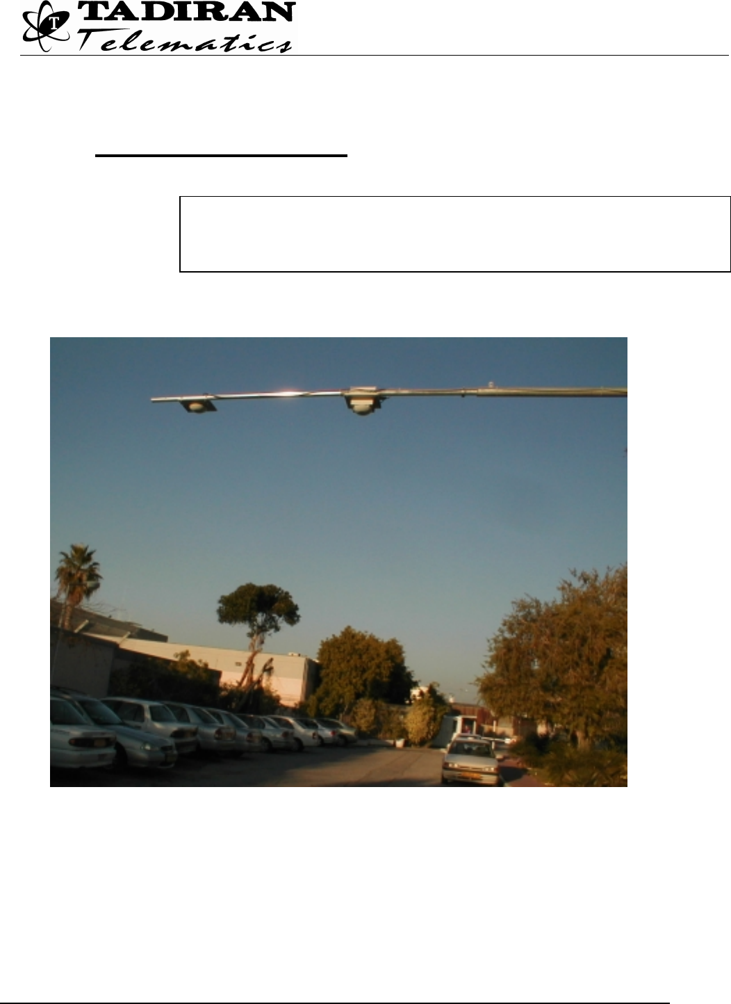
1. Mechanical Installation
The RSC has to be installed on a horizontal pipe above the center of a road lane.
The pipe has to be 1.5” up to 2” in diameter, and its length has to be sufficient to locate
the RSC over the center of the lane. (The width of a standard lane is about
3.6m ≅ 12ft). For longer pipes and for areas with extreme winds it is important to add
additional supports (still cables, etc.) to prevent bending of the pipe.
The RSC-900W should be installed by professional installers ONLY,
authorized ONLY by the local distributor – the “Operating Company”

RSC-900 User Man
Tadiran Telematics Proprietary
DRAFT
DRAFT
R:\Tadiran Telematics\14963\FCC
application\RSCW900 UserMan2.doc Rev. 1 March 18th, 2002 Pg.-4
1.1 Installation of RSC
Each unit, the main unit and the auxiliary antenna have two U stretchers that are
connecting the main plate to the horizontal pipe.
U stretchers
Main Unit
U stretchers
Aux. (Rx) antenna
RSC-900 User Man
Tadiran Telematics Proprietary
DRAFT
DRAFT
R:\Tadiran Telematics\14963\FCC
application\RSCW900 UserMan2.doc Rev. 1 March 18th, 2002 Pg.-5
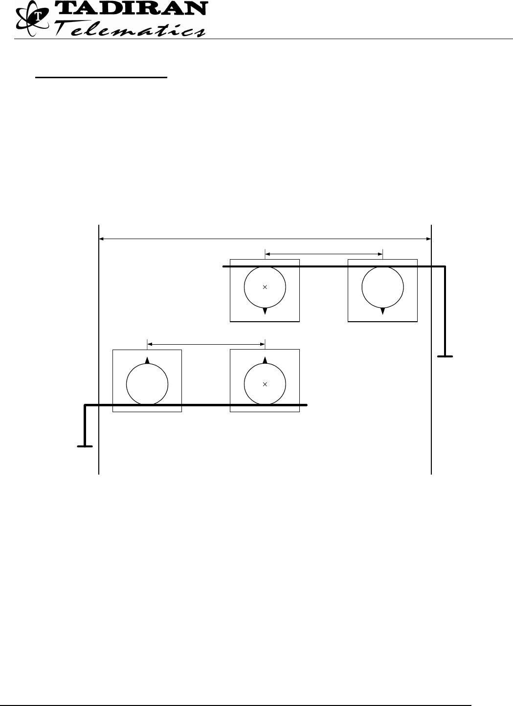
Installation Procedure
a) The aux. (Rx) antenna will be always installed above the center of the
driveway. The Main Unit can be installed on any side of the Aux. (Rx) antenna.
If a pole installation is used the Main Unit will always be closer to the pole!
b) Distance - The distance between the two units will be 2 meters (6.5 ft).
c) Direction – The antennas will be parallel to ground.
The Aux. (Rx) antenna will be located at the center of the driveway.
The main unit should be placed either to the left or to the right of the aux. (Rx)
antenna but the direction shall be observed so that both antennas shall be in the
same direction: if to the right, the direction shall be outward and if to the left,
the direction shall be inward – see above drawing.
2m (6.5 ft)
Driveway - Max 12m (39 ft)
Aux. antenna Main Unit
Inward
Pole on the right hand side
2m (6.5 ft)
Aux. antenna
Main Unit
Outward
Pole on the left hand side
RSC-900 User Man
Tadiran Telematics Proprietary
DRAFT
DRAFT
R:\Tadiran Telematics\14963\FCC
application\RSCW900 UserMan2.doc Rev. 1 March 18th, 2002 Pg.-6
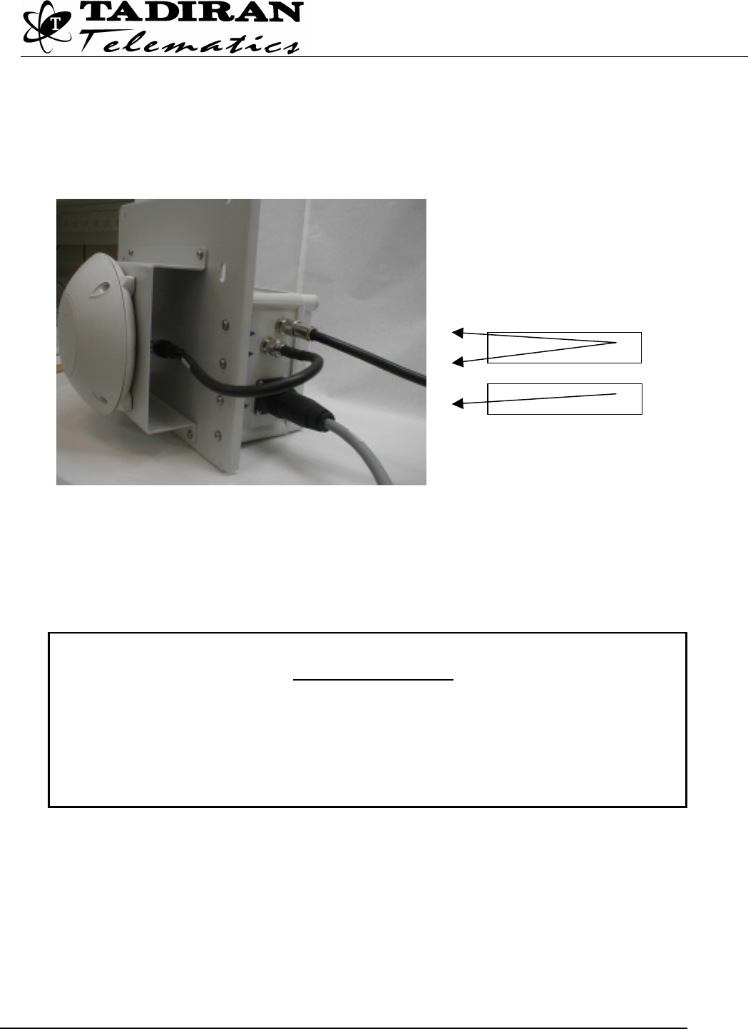
1.2 RSC cable connection
1. Connect the RSC Cable to RSC connector
The RSC-900 is delivered with a connected antenna (Tx) which is an integral part of the
RSC-900, and the aux. (Rx) antenna with its cable to be connected at the “AUX
ANTENNA” connector at the main unit.
WARNING:
The use of any antenna other than the one being an integral part of RSC-900 is
explicitly forbidden in accordance with FCC rules CFR47 part 15.204.
Failure to do so may void the product warranty and may expose the end user or
the service provider to legal and financial liabilities.
RSC Connector
Antenna Cables

RSC-900 User Man
Tadiran Telematics Proprietary
DRAFT
DRAFT
R:\Tadiran Telematics\14963\FCC
application\RSCW900 UserMan2.doc Rev. 1 March 18th, 2002 Pg.-7
2. Operation Instructions
2.1 Power and communication connections
• Connect the main power (24 V) to the RSC cable to pins No 23/24 (+) and
pins No.21/22 (-)
• Connect the Communication line to the RSC cable to pins No: 11 (TXD), 10
(RXD), and 21/22 (GND)
2.2 First Operation Test
2.2.1 PC Setup
(1) Prepare a PC with PC Anywhere® software installed on it.
(2) Connect the PC serial port (Com1) by means of PC Anywhere cable to the
communication line pins at the RSC cable.
2.2.2 RSC-900 Setup Parameters
(1) Double click on RSC icon to run pcAnywhere
(2) Click on Remote Control icon.
(3) The RSC application menu will appear in a blue DOS window
(4) Hit esc key several times until the Main Menu appears:
TADIRAN - Telematics Ver 5.0.0
Road Side Communicator 00000314 for e-Commander System
MAIN MENU
Manual operation
Script
Bit test
Rsc setup
Vtrack setup
Internet modem setup
Quit

RSC-900 User Man
Tadiran Telematics Proprietary
DRAFT
DRAFT
R:\Tadiran Telematics\14963\FCC
application\RSCW900 UserMan2.doc Rev. 1 March 18th, 2002 Pg.-8
TADIRAN - Telematics Ver 5.0.0
Road Side Communicator 00000314 for e-Commander System
RSC SETUP
Dial Number: 9, 5575739 {enter dial phone number, 9, if needed}
Maintenance Hour: 10 {enter maintenance hour: 0 to 23 (on the hour)}
Connection Type: MODEM
MODEM
RS232
INTERNET MODEM
Send File Interval (min): 30 {enter dialing time interval: 1 to 1440)}
(5) In the Main Menu, press R on the keyboard to RSC setup
(6) Get the following sub-menu
(7) With the keyboard arrow keys, bring the cursor to the required field and
modify it by keying in the new value(s):
Dial-up phone number - DMRC phone number
Maintenance hour
Connection type
Send file interval
(8) After modification, hit esc key and the following message appears:
Update RSC parameters ? (Y/N)
(9) Type Y (yes) on the keyboard to save the new parameters
(10) The message: RSC parameters have been updated is displayed for a short
period of time and the Main Menu reappears.
(11) Type S for Script
(12) Observe the application is running
(13) Shut down the PC.
(14) Disconnect pcAnywhere cable.
(15) Call operating center of the “Operating Company” and give the RSC-900
serial number and the local phone number for the RSC registration process in
the DMRC.
(16) Check that the RSC is working properly (read VTUs and file transfer to the
DMRC)

RSC-900 User Man
Tadiran Telematics Proprietary
DRAFT
DRAFT
R:\Tadiran Telematics\14963\FCC
application\RSCW900 UserMan2.doc Rev. 1 March 18th, 2002 Pg.-9

RSC-900 User Man
Tadiran Telematics Proprietary
DRAFT
DRAFT
R:\Tadiran Telematics\14963\FCC
application\RSCW900 UserMan2.doc Rev. 1 March 18th, 2002 Pg.-10
We will be happy to assist you at operating support center
Phone:
Fax:
“Operating Company” Name Logo and address
Here additional instructions will be added, according to the
“Operating Company” requests