ST Engineering Telematics Wireless T210 TNET User Manual Smart Street Light Specifications
Telematics Wireless Ltd. TNET Smart Street Light Specifications
User Manual

Tnet 210 Installation Instructions Rev 1.0 January 13, 2013 Page 1 of 3
Tnet 210 Module
Installation
Instructions
FCCID:NTAT210
January13,2013
Rev1.0
PROPRIETARY INFORMATION
ALL RIGHTS RESERVD, NO PARTS OF THIS DOCUMENT MAY BE REPRODUCED,
STORD IN RETRIEVAL SYSTEM, OR TRANSMITTED IN ANY FORM OR BY ANY
MEANS, ELECTRONIC, MECHANICAL PHOTOCOPYING, RECORDING OR
OTHERWISE WITHOUT THE PRIOR WRITTEN PERMISSION OF TELEMATICS
WIRELESS LTD. NOR USED IN WHOLE OR IN PART FOR ANY PURPOSE OR FOR
ANY CUSTOMER EXCEPT TELEMATICS WIRELESS.

Tnet 210 Installation Instructions Rev 1.0 January 13, 2013 Page 2 of 3
CAUTION
The User and the Installer should be aware that changes and modifications to the equipment not
expressly approved by Telematics Wireless could void warranty and the user's authority to
operate the equipment.
Professionally trained personnel should install the equipment.
The antenna used for this transmitter must be installed to normally provide minimum separation
distance of at least 20 cm from all persons and must not be co-located or operating in conjunction
with any other antenna or transmitter
ATTENTION
The digital portion of the transceiver has been tested and found to comply with the limits for a
Class B digital device, pursuant to part 15 of the FCC Rules. These limits are designed to provide
reasonable protection against harmful interference in a residential installation. This equipment
generates uses and can radiate radio frequency energy and, if not installed and used in accordance
with the instructions, may cause harmful interference to radio communications.
This device complies with Part 15 of FCC Rules. Operation is subject to the following two
conditions:
(1) This device may not cause harmful interference, and
(2) This device must accept any interference received, including interference that may cause
undesired operation.
Tnet 210 Installation Instructions Rev 1.0 January 13, 2013 Page 3 of 3
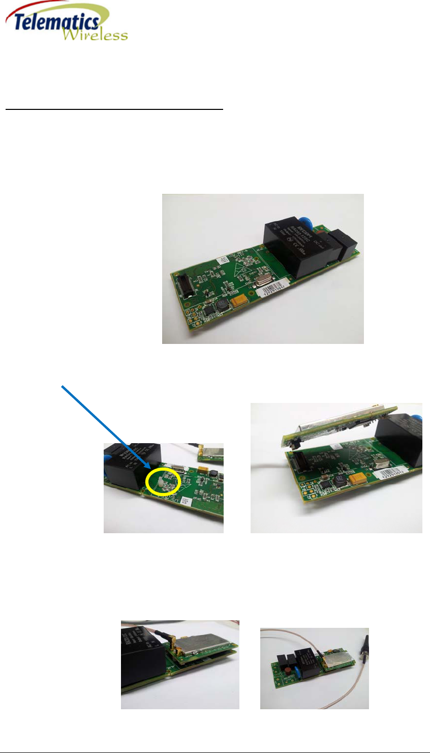
Tnet 210 Module Installation Instructions
Tnet 210 Module is installed on the carrier board and connected to external antenna using special
antenna cable.
1. Make sure that the carrier board power is off.
2. Connect Tnet 210 Module to the carrier board using board to board connectors and plastic
spacers.
3. Connect antenna cable to the Tnet 210 Module antenna's connector. The antenna cable is
specially designed for Tnet 210 Module using female MMCX connector at one end and
male TNC connector at the other end.