ST Microelectronics S R L MHBGW1 Bodyguardian Control Unit User Manual EW 40
ST Microelectronics S.R.L. Bodyguardian Control Unit EW 40
Contents
- 1. User Manual
- 2. Product literature
User Manual

Bodyguardian Control Unit
Base Kit
Operator Manual
SPMHBGW1-MAN
Rev. A
EDITION:
November 2011

BODYGUARDIAN CONTROL UNIT – BASE KIT Operator Manual
2
Contents
CHAPTER 1 ........................................................................................................................................ 4
INFORMATION ABOUT SAFETY ................................................................................................... 4
1.1 INFORMATION ABOUT THE MANUAL ......................................................................... 4
1.1.1 CONVENTIONS ........................................................................................................... 5
1.2 DECLARATION OF RESPONSIBILITY BY THE MANUFACTURER .......................... 6
1.3 USAGE RESTRICTIONS AND SAFETY PRECAUTIONS .............................................. 7
1.3.1 ELECTRIC SAFETY .................................................................................................... 7
1.3.2 SAFETY OF THE OPERATING ENVIRONMENT .................................................. 10
1.3.3 OTHER PRECAUTIONS ............................................................................................ 12
1.4 GRAPHIC SYMBOLS IN COMPLIANCE WITH THE IEC 60601-1 STANDARD . 13
1.5 OTHER GRAPHIC SYMBOLS ......................................................................................... 15
1.6 ATTENTION SYMBOL ..................................................................................................... 18
1.7 PRODUCT TRACEABILITY ............................................................................................ 18
1.8 VIGILANCE SYSTEM ...................................................................................................... 18
1.9 INFORMATION ABOUT RECYCLING OF MATERIALS ............................................ 22
1.10 ELECTROMAGNETIC COMPATIBILITY .................................................................. 23
1.10.1 RECOMMENDED DISTANCES FROM RADIOFREQUENCY (RF)
COMMUNICATION SYSTEMS .............................................................................................. 27
1.11 BIOCOMPATIBILITY AND INFECTIONS CONTROL ............................................. 29
1.12 CAUTION FOR THE U.S. MARKET ............................................................................ 29
CHAPTER 2 ...................................................................................................................................... 30
DESCRIPTION OF THE DEVICE ................................................................................................... 30
2.1 GENERAL OVERVIEW .................................................................................................... 30
2.2 BODYGUARDIAN CONTROL UNIT DESCRIPTION ................................................... 34
2.2.1 PATIENT CONNECTION .......................................................................................... 35
2.2.2 BLUETOOTH CONNECTION ................................................................................... 36
2.2.3 SIGNALING LEDS ..................................................................................................... 36
2.2.4 MULTIFUNCTION PUSH BUTTON ........................................................................ 38
2.3 BODYGUARDIAN CHARGING CRADLE ..................................................................... 39
2.4 AC/DC MEDICAL POWER SYPPLY ............................................................................... 40
2.5 DISPOSABLE ADHESIVE ELECTRODES PATCH ....................................................... 40
CHAPTER 3 ...................................................................................................................................... 41
POWERING UP THE DEVICE ........................................................................................................ 41
3.1 BATTERY CHARGING .................................................................................................... 41
3.1.1 RECORDING AUTONOMY ...................................................................................... 42
3.2 SWITCHING ON/OFF THE DEVICE ............................................................................... 43
CHAPTER 4 ...................................................................................................................................... 44
WORKING MODE............................................................................................................................ 44
4.1 PREPARING THE PATIENT ............................................................................................ 44
4.1.1 DISPOSABLE ADHESIVE ELECTRODES PATCH APPLICATION SITE ........... 44
4.1.2 PREPARING THE SKIN ............................................................................................ 44
4.1.3 PLACING THE DISPOSABLE ADHESIVE ELECTRODES PATCH ..................... 45
4.2 OPERATIVE MODES ........................................................................................................ 46
4.2.1 MONITORING MODE ............................................................................................... 46
4.2.2 STREAMING MODE.................................................................................................. 47
4.2.3 EVENT MONITORING .............................................................................................. 47
4.3 INSTALLATION AND INSTRUCTIONS FOR THE PATIENT ..................................... 48

BODYGUARDIAN CONTROL UNIT – BASE KIT Operator Manual
3
`
CHAPTER 5 ...................................................................................................................................... 49
MAINTENANCE .............................................................................................................................. 49
5.1 GENERAL INFORMATION ABOUT MAINTENANCE ................................................ 49
5.2 SAFETY CHECKS ............................................................................................................. 50
5.2.1 CONNECTORS ........................................................................................................... 50
5.2.2 BATTERY PACK........................................................................................................ 50
5.3 CLEANING THE DEVICE ................................................................................................ 51
5.4 PARTICULAR WARNINGS FOR CRITICAL COMPONENTS ..................................... 52
CHAPTER 6 ...................................................................................................................................... 53
TECHNICAL CHARACTERISTICS................................................................................................ 53
6.1 BODYGUARDIAN CONTROL UNIT .............................................................................. 53
6.2 DISPOSABLE ADHESIVE ELECTRODES PATCH ....................................................... 56
6.3 AC/DC MEDICAL POWER SUPPLY ............................................................................... 57
6.3.1 OPTION 1 .................................................................................................................... 57
6.4 BODYGUARDIAN CHARGING CRADLE ..................................................................... 57
CHAPTER 7 ...................................................................................................................................... 58
REQUEST FOR ASSISTANCE ........................................................................................................ 58
7.1 OBTAINING SERVICE ..................................................................................................... 58
7.2 PREVENTICE MAIN OFFICES ........................................................................................ 59
OPERATING OFFICES ............................................................................................................ 59

BODYGUARDIAN CONTROL UNIT – BASE KIT Operator Manual
4
CHAPTER 1
INFORMATION ABOUT SAFETY
1.1 INFORMATION ABOUT THE MANUAL
This document contains proprietary information. No part of this publication may
be photocopied or reproduced without the prior written permission of the
manufacturer PREVENTICE.
Information in this document is subject to change and revision without notice.
Issues:
First edition: SPMHBGW1-MAN - Rev. A - November 2011
This manual is to be considered as a component of the equipment. When installing
the equipment for the first time, the user should accurately check the content of
the Manual in order to verify its integrity and completeness.
In the event the Operator Manual should be ruined, incomplete or inadequate,
please contact PREVENTICE in order to immediately restore or replace the
uncompliant Manual.
The official version of the Operator Manual, of which PREVENTICE is directly
responsible, is the English versions. For countries in which languages other than
English are spoken, the official Manual is the one in the English version.
PREVENTICE does not undertake any responsibility for any translations in other
languages made by distributors or users.
The observance of the operating procedures and of the warnings described in this
Manual is a basic requirement for the correct working of the equipment and to
guarantee the patient’s and the user’s safety.
The Manual must be read in every part in front of the equipment before using it,
in order to become familiar with the operating procedures, the commands, the
connections to the peripheral instruments, and the precautions for a correct and
safe usage.
The Operator Manual should be kept, complete and readable in every part, in a
safe place, and, at the same time, it should be rapidly accessible to the user when
using the equipment.
This Operator Manual is intended for System Builder and not for the end-user of
the device.
The equipment Service Manual is available on request. This Manual contains all
information directed to the qualified staff in charge for servicing.
BODYGUARDIAN CONTROL UNIT – BASE KIT Operator Manual
5
`
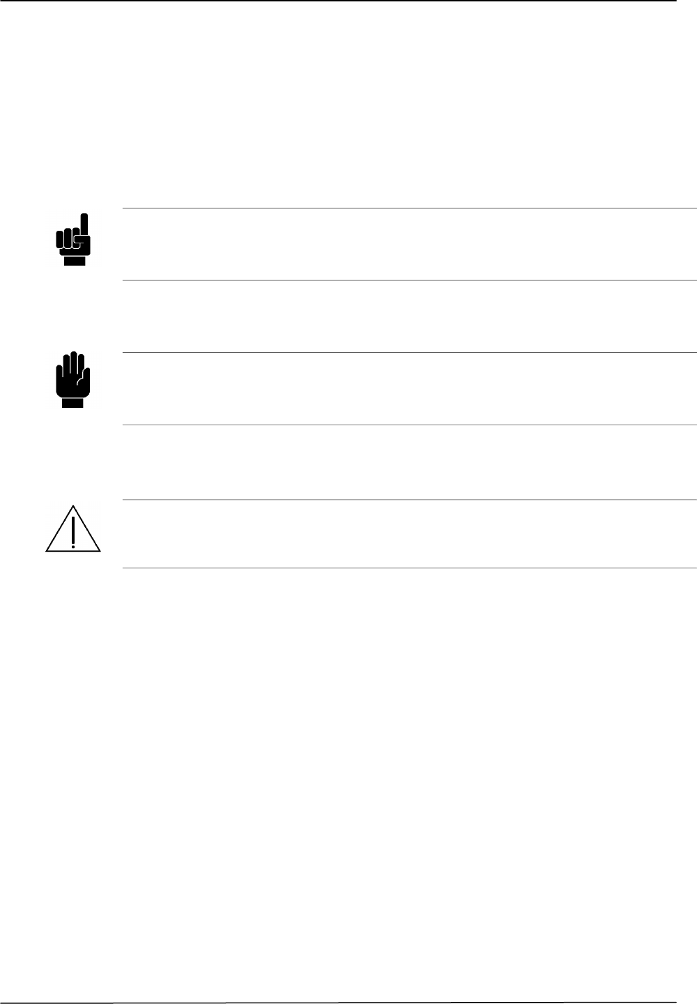
1.1.1 CONVENTIONS
In this Operator Manual the following conventions are used:
NOTE
The NOTE messages contain important information, which must be noticeable with
respect to the regular text. Usually they have useful information for the operator:
detailed data on the correct operating procedures of the instrument.
WARNING
The WARNING messages show in the manual before operations and procedures,
which must be strictly observed in order to avoid possible loss of data or damage
to the equipment.
ATTENTION
The ATTENTION messages show in the manual in correlation with the description
of procedures and operations, which could cause injury to the operator or to the
patient, if not correctly performed.

BODYGUARDIAN CONTROL UNIT – BASE KIT Operator Manual
6
1.2 DECLARATION OF RESPONSIBILITY BY THE MANUFACTURER
MANUFACTURER: PREVENTICE
1652 Greenview Drive SW
Rochester, MN 55092
Website www.preventice.com
Tel: +1 866-830-4043
PREVENTICE is responsible for safety, reliability and performances of the
equipment only when the equipment is used in compliance with the following
conditions:
Calibrations, modifications or servicing must be performed by qualified staff
expressly authorized by PREVENTICE.
The equipment must be opened and its internal parts must be accessed to by
maintenance qualified staff only expressly authorized by PREVENTICE.
The environment where the equipment is used must be in compliance with the
safety prescriptions.
The electric wiring of the building must be designed according to the standards
and perfectly working.
Parts of the equipment that can be replaced by the user and accessories must be
replaced with items of the same kind and with the same characteristics.
The connection of the equipment with peripherals or other instruments supplied
by the mains must be performed according to the IEC 60601-1-1 standards
(standards for electrical safety of medical electric systems) and to the IEC
60601-1-2 standards (standards for electromagnetic compatibility).
Usage and maintenance of the equipment and of its accessories must be
performed in compliance with the instructions described in this Manual.
This Manual must be kept complete and readable in every part.
The equipment is used and serviced until its “End of Life”.

BODYGUARDIAN CONTROL UNIT – BASE KIT Operator Manual
7
`
1.3 USAGE RESTRICTIONS AND SAFETY PRECAUTIONS
In order to guarantee the patient’s and the user’s safety as well as a correct
working of the equipment, it is necessary to operate within the consented
restrictions and adopt all the precautions listed below:
ATTENTION
Prior to usage, verify that all the safety requirements are satisfied.
The equipment must not be supplied by or connected to other instruments until
such safety conditions are restored.
1.3.1 ELECTRIC SAFETY
Leakage current
The maximum patient leakage current from the equipment, measured according to
the IEC 60601-1 standard (for Type BF) is less than 100 A.
However take care when using the equipment at the same time with other
instruments. In the event the patient is connected to several instruments at the
same time, it is necessary to remember that the sum of the leakage currents
determined by each instrument may exceed this value.
Patient Connection
All patient connections to the equipment are through the device using the proper
adhesive electrode patch provided. Any patient electrodes connected to the device
by any other means may constitute an unsafe condition that could result in injury
or death to the patient.
ATTENTION
All patient connections on the device are isolated from AC power ground.
Do NOT join these connections to earth ground or AC power ground since such an
action constitute an unsafe condition that could result in serious injury or
accidental death to the patient.
ATTENTION
The electrode through which the signal is captured from the body of the patient are
not part of the amplifier system, in any case it is MANDATORY to use only
electrode or sensor approved for commercial use by FDA (USA) or/and CE marked
(93/42 EEC directive and following amendment 2007/47/EC).

BODYGUARDIAN CONTROL UNIT – BASE KIT Operator Manual
8
To ensure the safety of the patient and the operator, please follow all the warnings
and caution listed in this manual.
Connect to the equipment the proper specified power supply only. In order
to guarantee the electrical safety requirements, the recharge of internal battery
pack of equipment, must be performed by means the proper medical AC/DC
adapter only. The power supply is supplied by PREVENTICE with the
equipment. The allowed models are:
Trademark FRIWO, Model FW7662M/06
To recharge the equipment place it on the Charging Cradle according to the
appropriate orientation (only one is possible due to the mechanical constraints)
and only after this operation connect the Charging Cradle to the AC/DC Power
supply and this last to the mains.
After the recharging operation is complete disconnect the AC/DC Power
supply from the mains and only after this operation remove the equipment from
the Charging Cradle.
Take care when using the equipment at the same time with other
instruments. In the event the patient is connected to several instruments at the
same time, it is necessary to remember that the sum of the leakage currents
determined by each instrument may endanger his life.
Take care when using the equipment at the same time with other radio-
frequency instruments. In the event the equipment is used in a surgery room
at the same time with a radio knife (Radio-Frequency instrument = RF), it is
necessary to hold the radio knife point as far as possible from the electrodes, in
order to reduce as much as possible the risk of RF currents making on such
electrodes and the consequent burns. Therefore it is necessary to use electrodes
with a larger surface contacting the patient body, in order to limit the RF
current density to acceptable values. In case it is not possible to use the proper
electrodes, it is recommended to disconnect the patient from the equipment
before using radio-frequency instruments.
The equipment is not protected against the defibrillator discharges. Please
remember that the equipment is not protected against the defibrillator
discharges; for this reason, in the event it should be necessary to use the
defibrillator, it is necessary to disconnect the patient from the equipment in
order to avoid the patient being burned in the electrode contact areas and the
equipment undergoing sever and irreversible damages.
Avoid contact of patient and electrodes with conductive metal items. When
the equipment is connected to other instruments supplied by the mains, the
whole input circuit to which the patient is connected is electrically isolated
(floating isolation). It is necessary to avoid the patient and any conductive part
connected to the patient (electrodes, connectors, and transducers) coming into
contact with conductive parts (ground included). Please observe this precaution
to avoid compromising the equipment isolation level. This precaution must be
observed in order to avoid that accessible metal parts of the device get in touch

BODYGUARDIAN CONTROL UNIT – BASE KIT Operator Manual
9
`
with external conductive parts thus damaging the isolation level of the
equipment.
Do not connect additional Multiple Portable Socket-Outlet or extension
cord. Multiple portable socket-outlet or extension cord shall not be connected
to the system.
Observe the IEC 60601-1-1 and the IEC 60601-1-2 standards in case of
connection with other instruments. The connection of the equipment with
other devices is allowed only when the safety requirements for the patient, the
user and the environment are not compromised. If the Manual does not contain
enough information about the possibility of interconnection with other devices,
the user should contact the manufacturer or the nearest authorized servicing
center to have information about the effects that coupling devices may have on
the patient, the user and the environment.
Replace damaged parts immediately. Cables, connectors, accessories, or
other parts of the equipment must be replaced immediately when damaged or
not working correctly. In these cases, contact the nearest authorized servicing
center.
Do not connect items (accessories and peripherals) which are not specified
as part of the system expressley indicated by PREVENTICE. In order to
guarantee all the safety requirements, it is necessary to use only the accessories
and peripherals specified in this Manual as part of the system, which have been
tested with the equipment. The usage of accessories and consumer goods
supplied by other manufacturers or not specifically indicated by
PREVENTICE does not guarantee the safety and the correct working of the
equipment. Use only peripherals in compliance with the standards of the class
they belong to.
Check the functionality of the system before starting any recording. It is
strongly recommended to check the overall functionality of the system before
starting any recording. In case any anomalies or malfunctioning should be
noticed, immediately disconnect the patient from the system (if a patient is
already connected), switch off the system and ask for service to qualified
personnel. In particular (for example) if, with a patient connected to the
system, some anomalous tracing, like isoelectric or greatly artefacted signal,
should be noticed on the monitor during recording: in this case if the problem
should not be solved with the assembly standard technique (poor electrode
connection, broken lead etc) immediately acts as above, disconnect the patient,
do not use the system and ask for servicing.
Periodically check that all the system works regularly during “long term
recording”. During “long term recording” (more than one hour) it is strongly
recommended to periodically check that all the system works regularly without
any sign of malfunctioning. If any anomalies or flat traces should be noted act
as in the previous warning. In particular any electrode site used for long term
must be checked for irritation and redness. Check each electrode periodically to

BODYGUARDIAN CONTROL UNIT – BASE KIT Operator Manual
10
evaluate the skin condition under the electrode. Redness, blistering and
permanent skin scarring can occur if electrodes are not regularly monitored.
Using the equipment on patients with a heart pace-maker is not allowed. It
is not allowed using the equipment in the case of patients with implanted
electric devices (or bed partners with implantable devices), especially heart
pace-makers, because the equipment may cause the cardiac stimulator
malfunctions. Patients with cardiac pacemakers should not undergo any
examination with this equipment without authorization and under the severe
control of a specialized physician. For the same reason it is also necessary to be
careful when using the equipment in proximity of operators or persons with
implanted electric devices
Rechargeable Battery Pack. The rechargeable battery pack installed in the
equipment contains one cell that is not accessible to the user and its
replacement should be performed only by qualified personnel, authorized by
PREVENTICE. Anyway, you should consider the following general warnings
(e.g. in case of disposal of replaced parts with technical assistance).
Do not let the ends of the battery pack to come in contact with metal
objects.
Keep away the battery pack from heat or flames.
Do not immerse the battery pack and avoid exposing it to rain or
moisture.
Avoid direct mechanical trauma to the battery pack.
Do not attempt to disassemble, puncture, incinerate or short-circuit the
battery. These operations may cause a fire or the emission of toxic
chemicals.
Charge the battery pack. In order to ensure the safety requirements, the
battery pack must be recharged only by using the proper Charging Cradle and
its medical AC/DC adapter, specifically provided by PREVENTICE together
with the equipment. The model of adapter to be used is:
Trademark FRIWO, Model FW7662M/06
1.3.2 SAFETY OF THE OPERATING ENVIRONMENT
The equipment is not designed to be used in locations with inflammable
vapors or gases that may cause explosions. The equipment must not be used
in atmospheres with a high concentration of oxygen or in buildings where
inflammable substances or anesthetic agents are present. The atmosphere is
considered as oxygen-saturated when the oxygen or nitrous oxide (NO2)
concentration contained in the environment is over 24%.
The equipment is not designed to be used in MRI area. The equipment
should be removed before Magnetic Resonance Imaging (MRI).
The equipment and its internal parts are protected against the inflow of
liquids according to IPX4 degree of protection. The equipment is protected

BODYGUARDIAN CONTROL UNIT – BASE KIT Operator Manual
11
`
against the dripping, spraying and splashing of water and relevant harmful
effects. Avoid submitting the equipment to the risk of water jetting or
temporary and continue immersion because its protection degree do not
guarantees protection of internal parts against ingress of liquids. Do not use the
equipment where such risks are present. Devices in which liquids have
accidentally penetrated must be immediately cleaned and checked by
authorized qualified staff.
Use of the equipment in humid Environment is allowed if conditions are
compliant to the environmental limits defined in the following bullet, which are
in accordance with the requirements of the applicable general and particular
IEC 60601 standards.
Use the equipment within the environmental limits of specified
temperature, humidity and pressure. The equipment is designed to work in
environmental conditions that, in compliance with the IEC 60601-1 directions
and the 60601-2-47, are defined as standard:
- temperature +10°C / +45°C
- relative humidity 10% / 95% RH
- atmospheric pressure 700 / 1060 hPa
The equipment could heat up during its normal use or battery recharge. This
aspect should be considered as a normal characteristic of the equipment due to
the high integration of the electronic circuitry inside. Never the equipment
heating up should be considered as a potential fault or as a defect of the
equipment itself.
Make sure the electric wiring of the building is efficient before connecting
the power supply to the mains. When the equipment (power supply of
Charging Cradle) is connected the environmental mains, make sure that the
building wiring is correctly functioning and efficient and compliant to the local
regulations and standards.
Be careful using the equipment in locations disturbed by strong magnetic
fields. The equipment is compliant with the EMC requirements
(Electromagnetic Compatibility) according to what specified by the IEC
60601-1-2 standard and 93/42/EEC European Directive. In every case it is
recommended to keep the equipment away from disturbance sources and
induced electromagnetic fields surpassing the values prescribed by the standard
in order to avoid any possible instabilities and malfunctioning of the
equipment. For more detail about device classification and minimum distances,
please refer to paragraph 1.11 “Electromagnetic compatibility” of the present
manual.
Be careful using the equipment near short-wave or micro-wave devices. If
the equipment is used in an area where there are also short-waves or micro-
wave devices, it is necessary to remember that these may cause instability and
interfere with the correct working of the equipment. Do not use the equipment
near X-ray or diathermy devices.

BODYGUARDIAN CONTROL UNIT – BASE KIT Operator Manual
12
1.3.3 OTHER PRECAUTIONS
Take care when using the equipment on patients who are pregnant. It is
necessary to be careful when using the equipment in the case of patients who
are pregnant. These patients should not undergo any examination with this
equipment without authorization and under the severe control of a specialized
physician.
The equipment is intended for adult use only with a weight greater than 10
Kgs.
Take care when using the equipment on patients with potentially life-
threatening arrhythmias requiring hospitalization. These patients should
not undergo any examination with this equipment without authorization and
under the severe control of a specialized physician.
Take care when using the equipment on patients with known skin allergies
or sensitivities to acrylic, hydrogel or silicone adhesives.
Take care when using the equipment on patients with friable skin. It is
necessary to be careful when using the equipment in the case of patients with
sensitive skin or skin disease, because the adhesive electrode may cause skin
irritation. Patients with sensitive skin should not undergo any examination with
this equipment without authorization and under the severe control of a
specialized physician.
Do not apply creams or lotion to the skin prior to use equipment. The
application of creams or lotion could cause a bad contacts of the electrodes and
a bas adhesion of the patch and consequently a bed signal acquisition
Bodyguardian is not waterproof. The device should be removed by patient
before bathing, showering or swimming.
Bodyguardian has a usage limited to one patient at a time.
BODYGUARDIAN CONTROL UNIT – BASE KIT Operator Manual
13
`
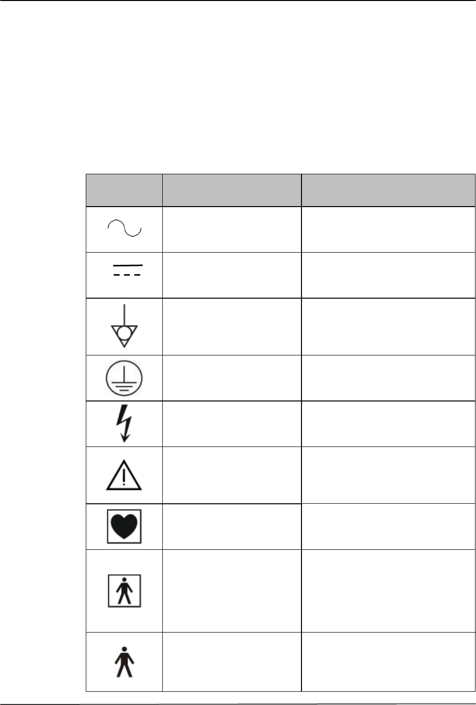
1.4 GRAPHIC SYMBOLS IN COMPLIANCE WITH THE IEC 60601-1
STANDARD
The following table shows description and localization of all graphic symbols in
compliance with the IEC 60601-1 safety standards present on the equipment
panels and/or on any other instruments or external devices to which the equipment
may be used in cojunction to or present in the same environment.
IEC 60601-1
SYMBOL
DESCRIPTION
POSITION
Alternating current
Symbol placed on the connection
points between the equipment and the
mains (alternating current source).
Direct current
Symbol placed on the connection
points to direct current source.
Equipotential terminal
Symbol placed on the outlet
connecting the equipment to the
equipotential node of the building, if
any.
Protective earth (ground)
Symbol placed on the connection
points between the equipment and the
protective grounding.
High voltage
Symbol placed on circuits or
equipment parts with high voltage.
Attention! Refer to the
attached instructions.
Symbol placed on items for which it is
important to read the Operator
Manual for relevant information (see
ATTENTION paragraph).
Device with CF-type applied
parts
Symbol placed on applied parts to
the patient with a CF-protection level.
Device with BF-type applied
parts
Symbol placed on applied parts to
the patient with a BF-protection level.
Device with B-type applied
parts
Symbol placed on applied parts to the
patient with a B-protection level.
BODYGUARDIAN CONTROL UNIT – BASE KIT Operator Manual
14
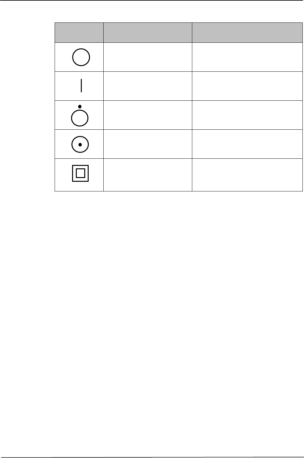
IEC 60601-1
SYMBOL
DESCRIPTION
POSITION
Off (disconnected from the
mains)
Symbol placed on the off/on positions
of the whole equipment general power
switch.
On (connected to the
mains)
Symbol placed on the off/on positions
of the whole equipment general power
switch.
Off (for a single part of
equipment)
Symbol placed on the off/on switch of
a single part of the equipment.
On (for a single part of the
equipment)
Symbol placed on the off/on switch of
a single part of the equipment.
Device with Class II
protection type against
electric shock
Symbol placed in the identification
label of the equipment.
BODYGUARDIAN CONTROL UNIT – BASE KIT Operator Manual
15
`
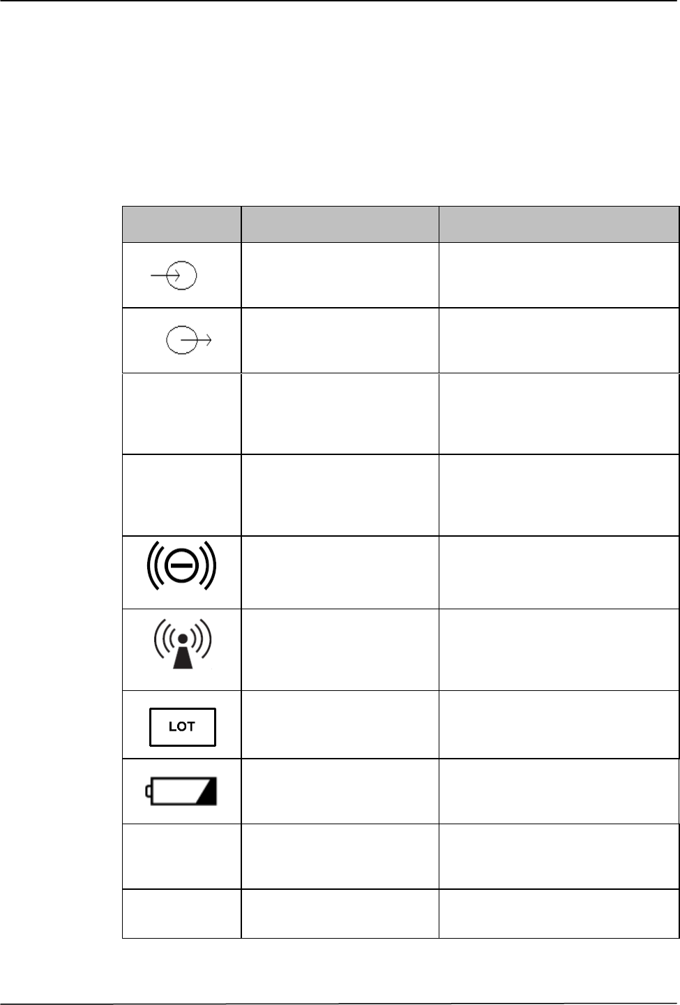
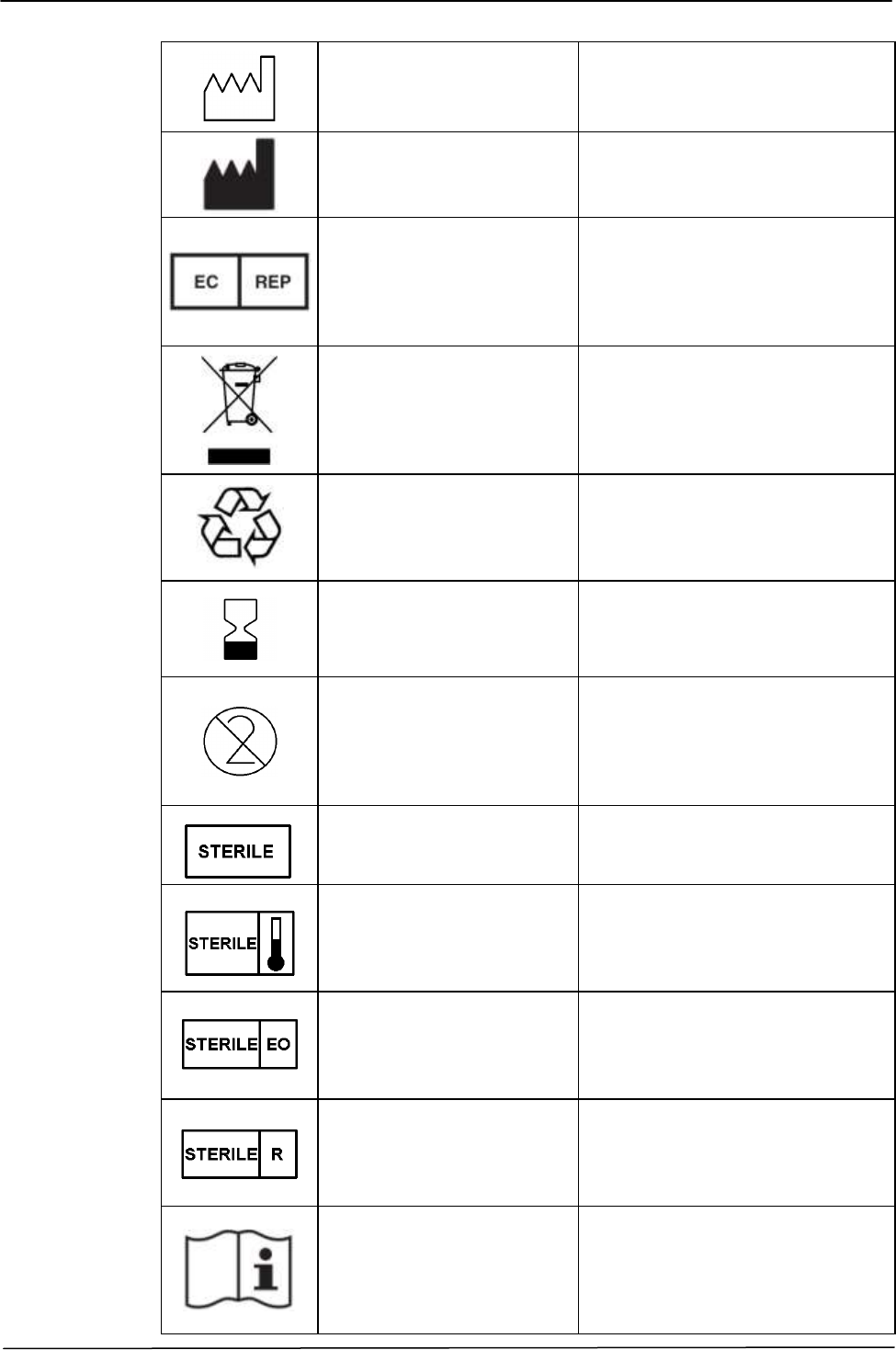
1.5 OTHER GRAPHIC SYMBOLS
The following table shows description and localization of all symbols placed on
the equipment panels and/or on any other instruments or external devices to which
the equipment may be used in cojunction to or present in the same environment.
SYMBOL
DESCRIPTION
POSITION
Input
Symbol placed on the signal input or
mains voltage input connectors of
the equipment.
Output
Symbol placed on the signal output
or the mains voltage output
connectors of the equipment.
Rx Only
Prescription Only
Symbol placed on the identification
label of the medical device indicating
that Federal (USA) law restricts this
product to sale by or on the order of
a physician.
IPX4
Degree of protection
against ingress of water
(spashing)
Symbol placed on the identification
label of the medical device indicating
that the device is protected against
the splahing of water.
Functional Mode and
Communications status
Symbol placed close the central led
of device to indicate the functioning
and communication status of the
device
Radio Frequency emitting
device (non-ionizing
electromagnetic radiation)
Symbol placed on the identification
label of the medical device to
indicate that the device emittes
Radio-Frequency for its normal
functioning.
Lot number
Symbol placed on the identification
label of the medical device together
with the device lot number.
Battery charge status
Symbol placed close the led of
device to indicate the battery charge
status and re-charge condition.
REF
Reference number
Symbol placed on the identification
label of the medical device together
with the device reference number.
SN
Serial number
Symbol placed on the identification
label of the medical device together
with the device serial number.
BODYGUARDIAN CONTROL UNIT – BASE KIT Operator Manual
16
Date of manufacture
Symbol placed on the identification
label of the medical device together
with the device manufacture date.
Manufacturer
Symbol placed on the identification
label of the medical device together
with the name and address of the
device Manufacturer
Authorized Representative
in the European Community
Symbol placed on the identification
label of the medical device together
with the name and address of the
device Authorized Representative in
the European Community.
Crossed-out wheeled bin
Symbol placed on the identification
label of the medical device. This
symbol indicates the prohibition of
throw the medical device in the
household wheeled bin device when
at its “end of life”.
Recyclable
Symbol placed on Battery Pack. The
symbol indicates the components of
the object are recyclable at the end
of life.
Use by
Symbol placed on the identification
label of the medical device together
with the device expiration date.
Do not reuse
Symbol placed on the identification
label of the medical device. This
symbol indicates that the device is a
disposable one and cannot be used
more than once.
Sterile
Symbol placed on the identification
label of the medical device indicating
a sterile device.
Sterilization with steam or
dry heat
Symbol placed on the identification
label of the medical device indicating
a sterile device and the sterilization
method used (steam or dry heat).
Sterilization with ethylene
oxide
Symbol placed on the identification
label of the medical device indicating
a sterile device and the sterilization
method used (ethylene oxide).
Sterilization by irradiation
Symbol placed on the identification
label of the medical device indicating
a sterile device and the sterilization
method used (irradiation).
Refer to the instructions for
Use/functioning.
Symbol placed on the identification
label of the medical device
recommending to refer to the
instruction for use/functioning for
more information about the usage of
the device.

BODYGUARDIAN CONTROL UNIT – BASE KIT Operator Manual
17
`
Temperature Limit
Symbol placed on the identification
label of the medical device together
with the indication of temperature
limits (high and low limits) for the
usage/storage of device.

BODYGUARDIAN CONTROL UNIT – BASE KIT Operator Manual
18
1.6 ATTENTION SYMBOL
The ATTENTION symbol shown below, placed on the equipment casing, refers
the user to the Operator Manual for information, warnings and suggestions which
are particularly important for a correct and safe use of the equipment.
In particular, when it is placed on connecting points or commands or led
indicators, this symbol refers the user to carefully read the Operator Manual for
instructions concerning the nature and safety of such connection and/or detailed
description of the commands and meaning of indicated events/situations for the
operator.
For location of the ATTENTION symbols placed on the equipment, please refer
to chapter 2 “Description of the Device” of this Operator Manual. This chapter
shows the pictures of the equipment panels with the corresponding commands,
connections, symbols, and labels. Each attention symbol comes with a detailed
explanation of its meaning.
1.7 PRODUCT TRACEABILITY
In order to guarantee the traceability of the product, according to what stated in
the ISO 13485 quality standard, QSR 21 CFR Parte 820 FDA, and the 93/42/EEC
European Directive on Medical Devices (and its revised version 2007/47/EC
directive), PREVENTICE kindly requests the original owner of the equipment to
give communication to our main offices of any conveyance of the product to third
parts, by sending a photocopy of the proper duly filled-in Product traceability
form (see enclosure 1.7), or by communicating in writing the data indicated in the
form. The data concerning the device can be found on its identification label.
The form shall be sent either directly or through any subsidiary or the nearest
authorized distributor to the any PREVENTICE operating office. The list of the
main PREVENTICE head and branch offices is contained in chapter “Request for
assistance” of this manual.
1.8 VIGILANCE SYSTEM
The device is subject to a vigilance system (post-marketing vigilance) that
PREVENTICE and their distributors and retailers apply to the products they put
on the market to safeguard the patient and the physician from serious or

BODYGUARDIAN CONTROL UNIT – BASE KIT Operator Manual
19
`
potentially serious hazards during the normal use of the equipment, in order to be
able to remove the source of such hazards with the best efficiency and timing.
To the purpose of helping PREVENTICE take any timely and effective corrective
measure, it is extremely important that the user performs a careful inspection of
the equipment performances in order to identify or foresee any dangerous
situation for the patient’s and the user’s health.
For this reason, the user shall give immediate communication of any malfunction
or deterioration of the characteristics or the performances of the equipment or any
mistake found in these instructions that caused or could cause serious damages to
the patient’s and the user’s health.
In this case, the user may send a photocopy of the proper duly filled-in Post-
Marketing Vigilance Form (see enclosure 1.8), or communicate in writing the
data indicated in the form.
The instrument’s data can be collected from it’s identification label.
The form shall be sent either directly or through any subsidiary or the nearest
authorized distributor to the any PREVENTICE operating office. The list of the
main PREVENTICE head and branch offices is contained in chapter “Request for
assistance” of this manual.

BODYGUARDIAN CONTROL UNIT – BASE KIT Operator Manual
20
Enclosure 1.7
PRODUCT TRACEABILITY FORM
To: PREVENTICE
1652 Greenview Drive SW
Rochester, MN 55092
c.a. Quality Assurance Department
System/device name……….................................................................................................
Device code / reference number (REF) ............................................................................
Device serial (SN) / lot number (LOT) .................................................................................
Name and address of the former owner .................................................................……....
.............................................................................................................................................
.............................................................................................................................................
.............................................................................................................................................
Name and address of the present owner .................................................................….......
....................................................................................................................................….....
................................................................................................................….........................
...............................................................................................................…..........…............
Date:...........................
Signature
...............................................
(please name in full)

BODYGUARDIAN CONTROL UNIT – BASE KIT Operator Manual
21
`
Enclosure 1.8
POST-MARKETING VIGILANCE FORM
To: PREVENTICE
1652 Greenview Drive SW
Rochester, MN 55092
c.a. Quality Assurance Department
System/device name.......................................................................................………..........
Device code/reference number (REF) ................................................................................
Device serial (SN)/lot number(LOT) .....................................…....................................…….
Description of the real or potential hazard……………………………………………………..
.............................................................................................................................................
.............................................................................................................................................
.............................................................................................................................................
.............................................................................................................................................
User’s comments/suggestions ............................................................................................
.............................................................................................................................................
.............................................................................................................................................
.............................................................................................................................................
.............................................................................................................................................
User’s address....................................................................................................................
Phone......................................................... Fax .............................................…................
Department where the device is installed.............................................................................
Person in charge of the department.....................................................................................
Data:...........................
Signature
...............................................
(please name in full)

BODYGUARDIAN CONTROL UNIT – BASE KIT Operator Manual
22
1.9 INFORMATION ABOUT RECYCLING OF MATERIALS
In accordance with the specific worldwide regulations, PREVENTICE aims to
continuously improve the design and the fitting of electromedical devices in order
to reduce as much as possible any negative impact on the environment caused by
the management of component parts, consumer materials, packaging and
discharge of devices when at their “end of life”.
Packaging materials were conceived and produced so as to allow the re-usage and
the salvage, including recycling, of most part of materials and to reduce the
quantity of garbage or residual products for discharge as much as possible. In
particular, packaging materials have been produced so as to limit the presence of
harmful metals and of other dangerous substances to minimum quantities in
emissions, ashes or lixiviation residual products. The total concentration levels of
heavy metals such as Lead, Cadmium, Mercury and hexavalent Chrome contained
in the packaging materials are in accordance with the limits established by the
directives in force related to this subject.
In order to cause minimum consequences to the environment, the design of the
device includes the highest possible miniaturization of the circuits, with the least
possible differentiation of materials and components, with a selection of
substances that guarantee the highest possibility to recycle and re-use the
components and to discharge them without risks for the environment.
The device is designed to guarantee the easy separation or disassembling of the
materials containing polluting substances from the others, in particular during the
operations of servicing and replacing parts. In particular, the largest plastic
components are marked according to their plastic contents in order to make it
easier to recycle the product.
ATTENTION
Please refer to local codes and regulations for proper disposal/recycle
requirements of packaging and consumer materials and of the device when at its
“end of life”.

BODYGUARDIAN CONTROL UNIT – BASE KIT Operator Manual
23
`
1.10 ELECTROMAGNETIC COMPATIBILITY
This medical device is designed for use in the electromagnetic environments
declared in the tables below, in compliance with the IEC 60601-1-2:2001 (second
edition) standard. The operator must assure that the device is used in an
environment compliant to this standard.
This device complies with Part 15 of the FCC Rules. Operation is subject to the
following two conditions: (1) this device may not cause harmful interference, and
(2) this device must accept any interference received, including interference that
may cause undesired operation.
The device is labeled FCC-ID S9NMHBGW1.
Table 1 - Electromagnetic Emissions
Emission Test
Compliance
Electromagnetic Environment
Radiated and
conducted RF
emissions
CISPR 11
Group 1
This medical device use RF energy only for
its internal function. Therefore, the RF
emission is very low and not likely to cause
any interference in nearby electronic
equipment.
Radiated and
conducted RF
emissions
CISPR 11
Class B
This medical device is suitable for use in all
establishments, including domestic directly
connected to the public low voltage power
supply network that supplies buildings used
for domestic purpose.
Harmonic emissions
IEC 61000-3-2
Complies
Class A
Voltage fluctuations/
flicker emissions
IEC 61000-3-3
Complies

BODYGUARDIAN CONTROL UNIT – BASE KIT Operator Manual
24
Table 2 - Electromagnetic Immunity
Immunity
Test
IEC 60601-1-2 Test
Level
Compliance
Electromagnetic
environment
Electrostatic
Discharge
(ESD)
IEC 61000-4-2
6 kV in contact
8 kV on air
IEC 60601-1-2
Test Levels
Residential/Hospital
(Note 1)
Electrical fast
transient/burst
IEC 61000-4-4
2 kV for power supply
line
1 kV for input/output
lines >3m
IEC 60601-1-2
Test Levels
Residential/Hospital
(Note 2)
(Note 3)
Surge
IEC 61000-4-5
1/0.5 kv differential
mode
2/1/0.5 kV common
mode
IEC 60601-1-2
Test Levels
Residential/Hospital
(Note 2)
(Note 3)
Voltage dips,
short
interruptions
and voltage
variations on
power supply
input lines
IEC 61000-4-
11
0 % of rated voltage
(voltage dip 100 %)
for 0.5 cycles
40 % of rated voltage
(voltage dip 60 %)
for 5 cycles
70 % of rated voltage
(voltage dip 30 %)
for 25 cycles
0 % of rated voltage
(voltage dip 100 %)
for 5 seconds

BODYGUARDIAN CONTROL UNIT – BASE KIT Operator Manual
25
`
Power
frequency
(50/60 Hz)
magnetic field
IEC 61000-4-8
3 A/m

BODYGUARDIAN CONTROL UNIT – BASE KIT Operator Manual
26
Table 3 - Electromagnetic Immunity for non-life supporting equipment
Immunity
Test
IEC 60601-1-2 Test
Level
Compliance
Electromagnetic
environment
Portable and mobile RF
communications equipment
should be used no closer to
any part of this medical
device, including cables, than
the recommended separation
distance calculated from the
equation applicable to the
frequency of the transmitter
(table 4 - Recommended
separation distance).
Radiated RF
fields
IEC 61000-4-
3
3 V/m
from 80 MHz to 2.5
GHz
IEC 60601-1-
2
Test Levels
3 V/m
d = 1.2 P 80 MHz a 800
MHz
d = 2.3 P 800 MHz a 2.5
GHz
Radiated RF
fields
IEC 61000-4-
6
3 V
from 150 kHz to 80
MHz
IEC 60601-1-
2
Test Levels
3 V
d = 1.2 P
Where P is the maximum
output rating of the
transmitter in watts (W)
according to the transmitter
manufacturer and d is the
recommended separation
distance in meters (m).
Field strengths for fixed RF
transmitter, as determined by
an electromagnetic site
survey, should be less then
the compliance level in each
frequency range.
Interference may occur in the
vicinity of equipment marked
with the following symbol:

BODYGUARDIAN CONTROL UNIT – BASE KIT Operator Manual
27
`
Measures to be taken
Note 1: The floor should be in antistatic material (wood, ceramic, ect.). If covered by synthetic
material, relative humidity should be maintained at least at 30%.
Note 2: The quality of the electrical power supply and the mains frequency magnetic fields
should be typical of domestic, commercial and hospital environments.
Note 3: If the operator has to work without a break while power supply is interrupted, it is
necessary to have power supplied through a UPS (Uninterruptible Power Supply) unit.
1.10.1 RECOMMENDED DISTANCES FROM RADIOFREQUENCY (RF)
COMMUNICATION SYSTEMS
As stated in the chapter 1 “Information about safety” of this operator manual, it is
recommended to not use Radiofrequency (RF) transmission system near the
medical device. RF systems can cause interference which may cause instability
and interferences with the correct working of the equipment and it may alters the
signal acquired tracing.
The operator can prevent interference caused by electromagnetic field by
maintaining a minimum distance between the medical device and the RF
communication system being used (cell phones, mobile phones, etc,).
The following table shows the minimum distances in meters, according to the
maximum power at RF system output.
Table 4 – Recommended separation distance for non-life supporting equipment
Rated maximum
output power of
the transmitter
(W)
Separation distance according to frequency of
transmitter (m)
150KHz to
80MHz
d=1.2× P
80Mhz to
800MHz
d=1.2× P
800MHz a
2.5GHz
d=1.2× P
0.01
0.12
0.12
0.23
0.1
0.38
0.38
0.73
1
1.2
1.2
2.3
10
3.8
3.8
7.3
100
12
12
23
For transmitters rated at the maximum output power not listed above, the recommended
separation distance d in meters (m) can be estimated the equation applicable to the frequency of

BODYGUARDIAN CONTROL UNIT – BASE KIT Operator Manual
28
the transmitter, where P is the maximum output power rating of the transmitter in watts (W)
according to the transmitter manufacturer.
Note:
(1) at 80MHz and 800MHz, the separation distance for the higher frequency range applies.
(2) These guidelines may not apply in all situations. Electromagnetic propagation is affected
by absorption and reflection from structures, objects and people
The operator must remember that the intensity of the electromagnetic fields
generated by fixed transmitters (radio-base stations for cellular or cordless phone,
TV and radio transmissions, amateur radio transmission, etc.) cannot be
predicated on theoretical basis.
Consequently, a direct measure may be necessary in the environment where is
used the medical device.
If the intensity of the electromagnetic fields exceeds that specified in the
immunity levels shown in the previous tables, and the medical device behaves
incorrectly working, additional measures may be necessary. I.e. orienting or
locating the medical device in a different way.

BODYGUARDIAN CONTROL UNIT – BASE KIT Operator Manual
29
`
1.11 BIOCOMPATIBILITY AND INFECTIONS CONTROL
No system component is intended to be in contact with the patient during the
usage.
Electrodes and sensors are not intended to be parts of the Bodyguardian Control
Unit product.
All the body contacting material are not part of the MD, in any case remember
that electrodes and sensors MUST meet the requirements of 93/42/EEC Medical
Devices Directive and its revised version (CE marked) for the European
Community and MUST have FDA clearance/approval for the U.S. market.
1.12 CAUTION FOR THE U.S. MARKET
Federal law (USA) restricts the device to sale by or on the order of a licensed
practitioner or therapist.
Medical professionals prescribe the Bodyguardian system to obtain physiological
data from their patients. It does not replace direct communication between
physicians and patients and does not summon physicians or emergency personnel.

BODYGUARDIAN CONTROL UNIT – BASE KIT Operator Manual
30
CHAPTER 2
DESCRIPTION OF THE DEVICE
2.1 GENERAL OVERVIEW
The Bodyguardian Control Unit is a wearable battery power device intended for
use as a part of a Multi-Parameter Analysis System and is designed to be used by
a System Builder in a Multi-Parameter Analysis Application.
The Bodyguardian Control Unit is worn on the chest for the acquisition, recording
and transmission via a Bluetooth radio link of physiological parameters to
external host devices which can analyze by the suitable proper Application
Software and/or forward the data to additional storage elements or system.
The Bodyguardian Control Unit is also capable to record symptomatic and
asymptomatic events. The Bodyguardian Control Unit continuously records,
stores and periodically transmits the following physiological data:
Single lead ECG
Heart rate
Respiratory rate
Posture
Activity
Event marker
The Bodyguardian Control Unit is used for ambulatory monitoring of non-lethal
cardiac arrhythmias. Bodyguardian Control Unit is a wearable electronic device
that is worn on the chest. The device includes a disposable fabric adhesive
component that attaches to the subject and connects to the enclosed electronic
components.
The device will be worn intermittently or continuously for up to a 30-day period.
The recordings will be stored on the Bodyguardian Control Unit and transmitted
by the device via Bluetooth communication to an external Associated Device
(Android smartphone or other). The device is prescription only.
The Bodyguardian Control Unit recorder is intended to be used in a:
“Home Care” environment without clinicians surveillance.
“Clinic Care” environment with clinicians surveillance
The device is intended to be used by two different categories of end-users:
1. The patient which will use the device for continuous monitoring applications
and who will have to:
apply the device to the body by connecting the Bodyguardian Control Unit
to the disposable patch and attaching it to the selected body area;

BODYGUARDIAN CONTROL UNIT – BASE KIT Operator Manual
31
`
turn it on and off by using the appropriate button;
manage the recharging of the Bodyguardian Control Unit using the
dedicated charging station and power supply cable;
monitor the status of the device by looking at the led lights and colors
manage the devices by using the mobile phone application
2. The clinicians who will eventually subscribe the use of the device to the
patient and who will be in charge of:
Setting the initial thresholds and baselines for the parameters based on
patient’s conditions to personalize it (on Multi-Parameter Analysis System
side)
Reviewing the data acquired and transmitted from the device to the remote
server location (Multi-Parameter Analysis System) for diagnosis, trends
monitoring and in general clinical evaluations.
Depending on the Environment, optional algorithms and/or thresholds (settable
via host software) can be used to generate measurements on an advisory basis for
patients. These are presented for:
Review and interpretation by the clinician, based upon knowledge of the
patient.
Results of the physical examination.
The data provided by the Bodyguardian Control Unit are exclusively intended to
be used by trained medical personnel to assist patients that requires monitoring of
physiological parameters with reference of the followings context:
Screening of patients with symptoms suggesting arrhythmia over a
minimum 24-hour period.
Screening and off line evaluation of HR and Breath variability if the nature
of this variability cannot determine a Life-threatening for the patient.
Not intended to allow direct diagnosis or monitoring of vital physiological
processes parameters (for instance cardiachearth rate, respiration), where
the nature of variations is such that it could result in immediate danger to
the patient.
Not intended for therapeutic purpose.
The “Body Guardian” Recorder is intended for adult use only with a weight
greater than 10 Kgs, without race exclusion. Patient with implanted device are
excluded to wear this device.
The Bodyguardian Control Unit is intended for System builder user in order to
create a complete remote ambulatory monitoring system including Bodyguardian
Control Unit kit, communication hub (Android smartphone or other) and System
Server.

BODYGUARDIAN CONTROL UNIT – BASE KIT Operator Manual
32
All aspects related to safety and effectiveness of the whole ambulatory multi
parametric monitoring system is under the complete responsibility of System
Builder.
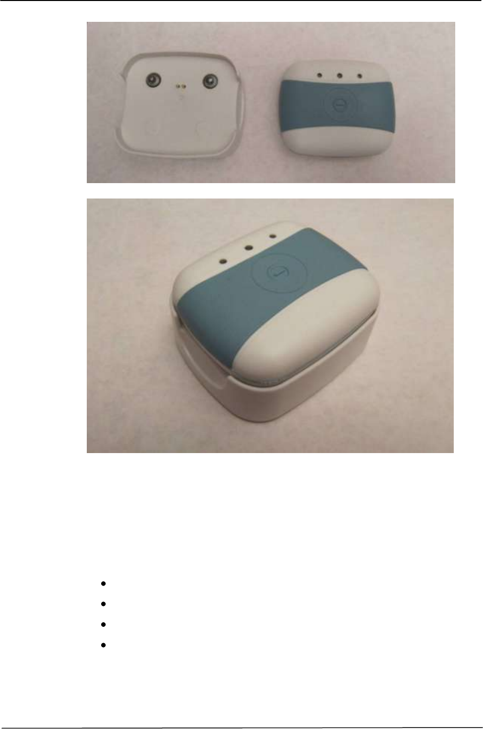
The Bodyguardian Control Unit is provided with a Base Kit containing the
following base elements:
The Bodyguardian Control Units (2 units)
The Bodyguardian Charging Cradle
The AC/DC medical power supply
The Disposable adhesive electrodes patch
The User Manual
The Android Smartphone
The Bodyguardian Disposable adhesive electrodes patch, the AC/DC medical
power supply, the User Manual and eventually the Smartphone are provided by
the System Builder.
Here below the pictures of the different elements composing the Bodyguardian
Control Unit base kit:
BODYGUARDIAN CONTROL UNIT – BASE KIT Operator Manual
33
`
Figure 2-1 Components of Bodyguardian Control Unit base kit
BODYGUARDIAN CONTROL UNIT – BASE KIT Operator Manual
34
2.2 BODYGUARDIAN CONTROL UNIT DESCRIPTION
The following figures (2-2 and 2-3) show the Bodyguardian Control Unit:
Figure 2.2 – Bodyguardian Control Unit: front view
Figure 2.3 - Bodyguardian Control Unit: back view
In the previous figures the following components can be found:
1. Signaling Leds
2. Push button
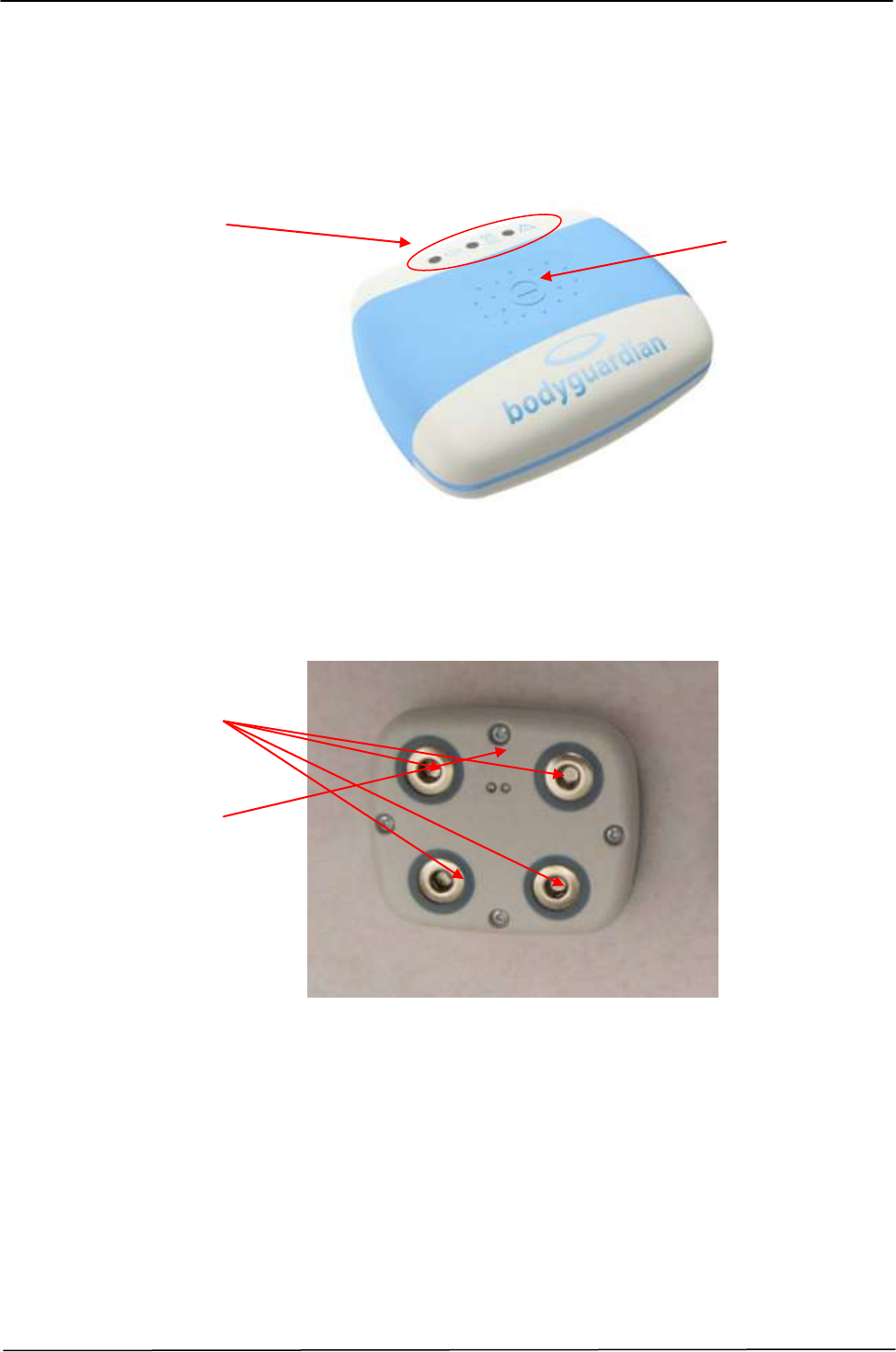
3. Charger connectors (n° 2 contacts)
4. Patient connectors (n° 4 snap contacts to connect to Disposable adhesive
electrodes patch) with the following configuration reading in clockwise sense
from the Top-Left angle: INJ2, INJ1, SENSE1, SENSE2. The connection of
the device to the disposable adhesive patch is possible, due to mechanical
constraints, only in one correct way.
1
3
4
2
INJ2
INJ1
SENSE1
SENSE2
BODYGUARDIAN CONTROL UNIT – BASE KIT Operator Manual
35
`
2.2.1 PATIENT CONNECTION
Biologic input signals are acquired by Bodyguardian Control Unit through the
patient connectors (fig. 2.4).
Figure 2.4 - Patient connectors
which uses the 4 ECG snaps to interconnect the Bodyguardian Control Unit with
the Disposable electrodes patch.
The connection is guaranteed through the four snaps on the SnapStrip.
Figure 2.5 - Patient connection
ATTENTION
All the patient applied parts and corresponding input sockets of Bodyguardian
Control Unit (patient inputs) are electrically isolated according to IEC 60601-1
standard requirements for internally powered, Type BF equipments. This
characteristic is indicated to the operator with the proper symbol placed on the
external cover of the device.
BODYGUARDIAN CONTROL UNIT – BASE KIT Operator Manual
36
2.2.2 BLUETOOTH CONNECTION
The Bodyguardian Control Unit is equipped with an integrated Bluetooth network
interface (for Protocol Specification please refer to the document
BGP110006_Commend_Interface_Specifciations) that allows to establish a
pairing connection with an external Associated Device (e.g. Android smartphone
or other).
The Bluetooth interface can be used to configure the Bodyguardian Control Unit
and to transmit the data registered and stored on the Bodyguardian Control Unit to
the Associated Device.
The communication between Bodyguardian Control Unit and the external
Associated Device is handled via software.
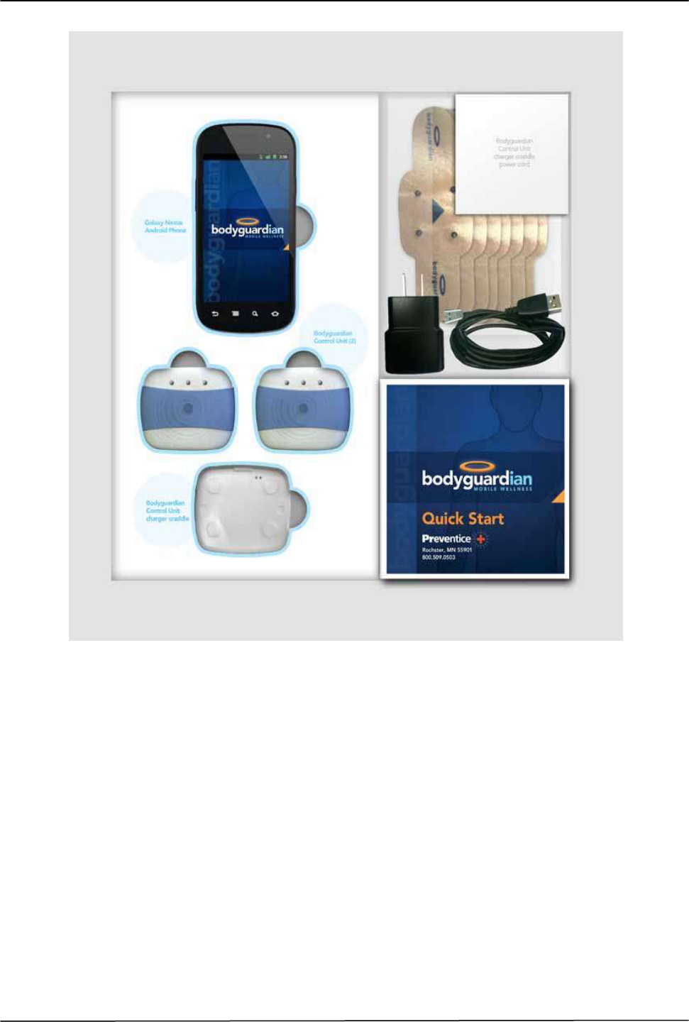
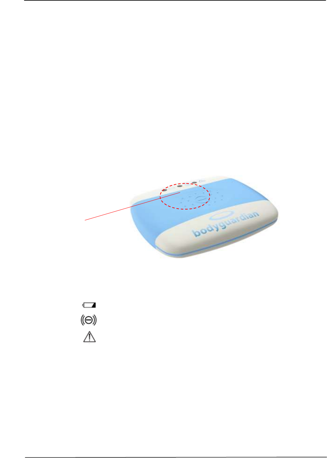
2.2.3 SIGNALING LEDS
The following figure shows the signalling Leds placed on the front cover of the
Bodyguardian Control Unit.
Figure 2-9 – Signaling Leds
The 3 Monocolor Leds indicate device status and conditions.
The Leds indicates the following conditions:
LED 1 – Yellow: indicates the Device Charging Status;
LED 2 – Green: indicates the Device Operative Mode Status;
LED 3 – Yellow: indicates special Events occurrences.
The following table summarizes the possible Leds configuration status and
relative significance:
Signalling
LEDS
BODYGUARDIAN CONTROL UNIT – BASE KIT Operator Manual
37
`
Led states
OFF
Led Off
SLOW
Led Turned on every 10 Sec & OnTime 1000 ms
MEDIUM
Led Turned on every 1 Sec & OnTime 500 ms
FAST
Led Turned on every 0.5 Sec & OnTime 100 ms
ON
Led On
d.n.c.
Do Not Care
LED Priority
High
H
Medium
M
Low
L
HW/SW driven
SW driven
SW driven
LED1
LED2
LED3
Charging Led
Operative Led
Event Led
Yellow
Green
Yellow
STATE
STATE
Priority
STATE
Priority
Device
BGD OFF
OFF
OFF
OFF
ON charge
ON (by HW)
d.n.c.
d.n.c.
FULL charge
OFF
d.n.c.
d.n.c.
Identification
d.n.c.
Medium-Q
H
Medium-QN
H
Modes
IDLE
d.n.c.
ON
L
OFF
ENGAGED
d.n.c.
L
d.n.c.
SERVICE
ON (by SW)
Medium-Q
H
Medium-QN
H
---> SERVICE (FOTA)
ON (by HW)
d.n.c.
d.n.c.
---> SERVICE (ACCEPT-
TEST)
Test driven
MONITORING
d.n.c.
SLOW
L
d.n.c.
STREAMING
d.n.c.
FAST
M
d.n.c.
Events
Symptomatic Event
Not considered
Electrodes Detached
d.n.c.
d.n.c.
FAST
M
Low Battery Level
SLOW (by SW)
d.n.c.
d.n.c.
Communic.
Active Connection
(In/Out)
d.n.c.
FAST
M
d.n.c.
Data Transfer Failure
d.n.c.
d.n.c.
ON
L

BODYGUARDIAN CONTROL UNIT – BASE KIT Operator Manual
38
2.2.4 MULTIFUNCTION PUSH BUTTON
The following figure shows the multifunction push button placed on the front
cover of the Bodyguardian Control Unit.
Figure 2-10 – Multifunction push button
The push Button turns ON and OFF the device and insert symptomatic events
notification from the patient. The button has the following functional modes:
- Power on/off
When the device is OFF, press the button with a short pressure to Turn ON
the device (T>0sec).
When the device is ON, press the button with a long pressure to Turn OFF
the device (T>10sec).
- Additional functions
When the device is ON and operative, click the button to record a
symptomatic event. The pressure time must be < 10sec to prevent the
device to Turn OFF.
Multifunction
push button
BODYGUARDIAN CONTROL UNIT – BASE KIT Operator Manual
39
`
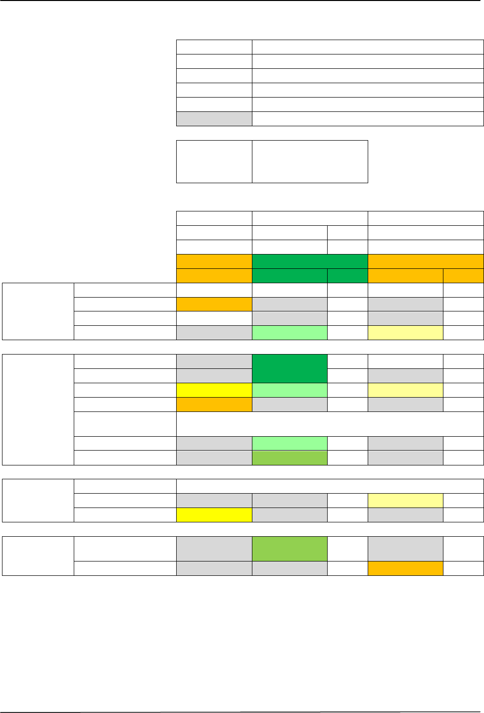
2.3 BODYGUARDIAN CHARGING CRADLE
The Bodyguardian Control Unit is provided with a proprietary Charging Cradle
which must be used to re-charge the internal battery (Figure 2.11).
Figure 2-11 – Bodyguardian Charging Cradle – Upper view
Figure 2-12 – Bodyguardian Charging Cradle – Side view
In the previous figures the following components can be found:
5. Recharging contacts (to charge the Bodyguard Control Unit)
6. Snaps (to properly place and hold the Bodyguardian Control Unit)
7. Input voltage connector (connection of AC/DC medical adapter)
7
5
6
BODYGUARDIAN CONTROL UNIT – BASE KIT Operator Manual
40
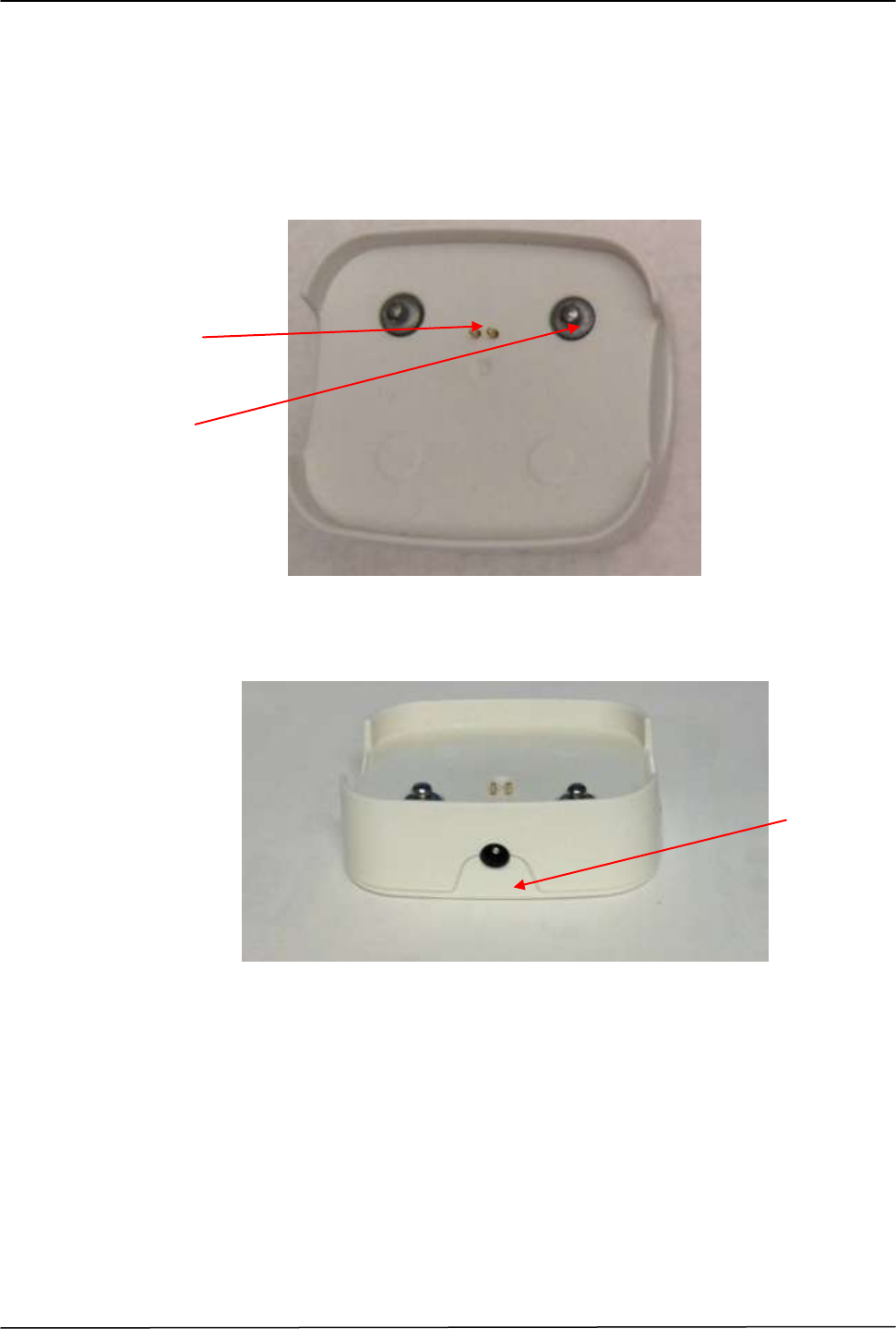
2.4 AC/DC MEDICAL POWER SYPPLY
The following figure shows the specified medical AC/DC adapter for
Bodyguardian Charging Cradle powering up and their parts:
8. AC/DC Medical power supply
9. Mains plug
10. Isolated voltage output connector with cable
Figure 2-13 – AC/DC Medical Power Supply
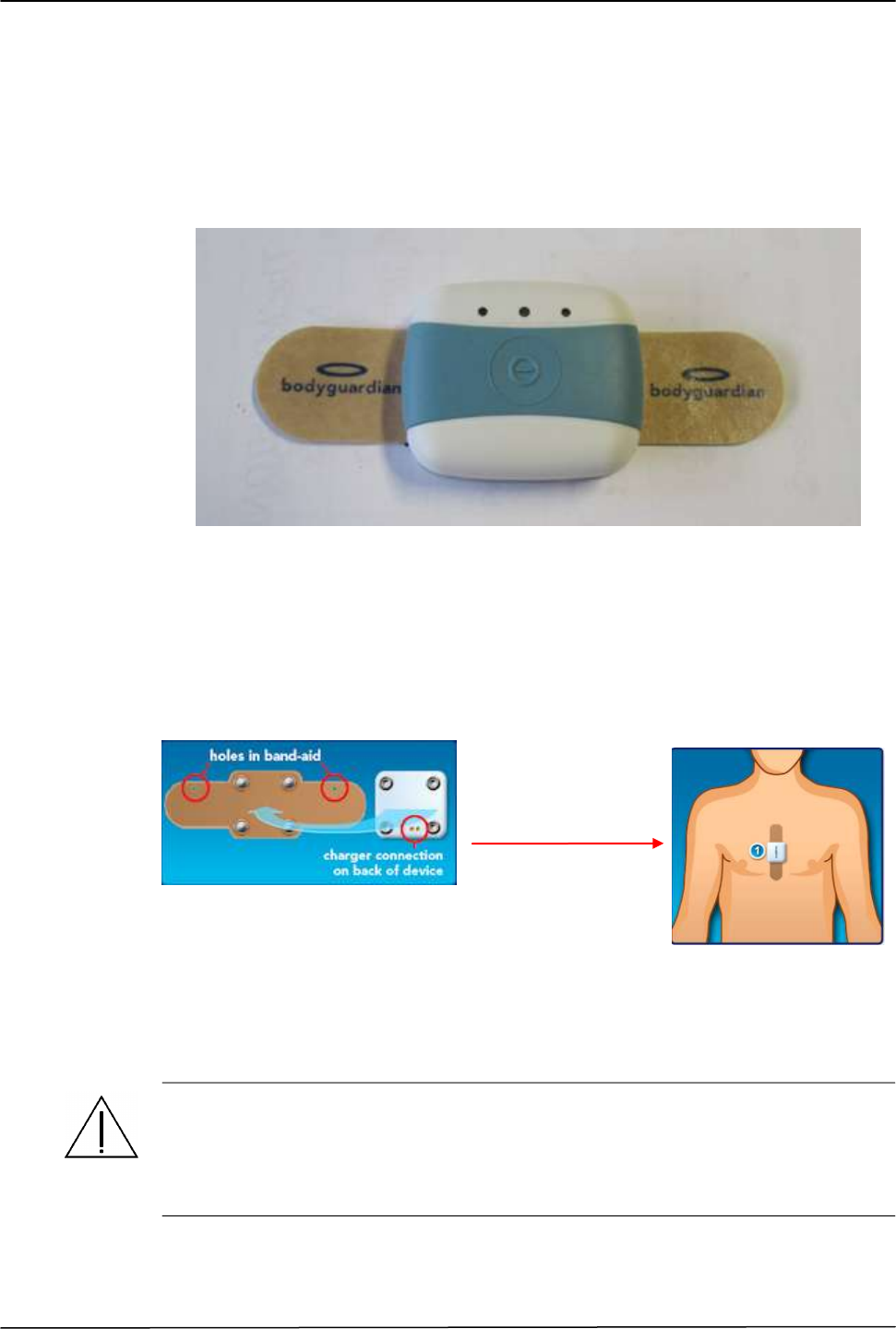
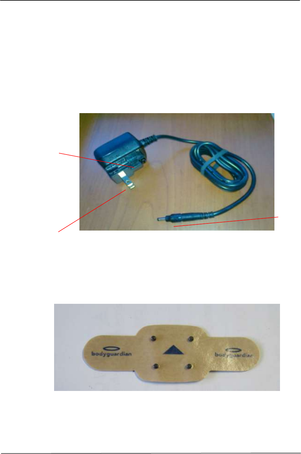
2.5 DISPOSABLE ADHESIVE ELECTRODES PATCH
The following figure shows the disposable adhesive electrodes patch, which
integrates four electrodes used to acquire ECG and Bio-impedance signals.
Figure 2-14 – Disposable adhesive electrodes patch
It is attached to the patient’s skin and is connected to the Bodyguardian Control
Unit using four snaps. Each SnapStrip has a water resistant layer, ECG electrodes
and snaps that create an electrical connection to the Bodyguardian Control Unit.
8
10
9

BODYGUARDIAN CONTROL UNIT – BASE KIT Operator Manual
41
`
CHAPTER 3
POWERING UP THE DEVICE
The Bodyguardian Control Unit is powered through an internal battery. The
battery is rechargeable by means of the Bodyguardian Charging Cradle connected
to the mains trough the AC/DC power supply.
3.1 BATTERY CHARGING
While operating, if the Bodyguardian Control Unit detects that the battery level is
below a certain level (Low Battery Level as defined in the Preventice
Requirement Document) of the full capacity, LED 1 ( ) starts blinking with a
slow frequency, 1 second every 10 seconds, indicating that the device needs to be
recharged.
In this case, switch off Bodyguardian Control Unit and remove it from the strip
placed on the patient.
Additionally, if the Bodyguardian Control Unit detects that the battery level is
below a safety level (Critical Battery Level as defined in the Preventice
Requirement Document) of the full capacity, the Bodyguardian Control Unit starts
an automatic power off procedure to safely close the application and guarantee the
integration of the data sampled and stored up to that moment.
ATTENTION
If the device is not switched off manually by the user, when approaching a very low
battery level, the device will initiate an automatic power down procedures which
will allow uploading all the data acquired and safely switch off the device.
To recharge the Bodyguardian Control Unit place it on the Charging Cradle
according to the appropriate orientation (only one is possible due to the
mechanical constraints) and only after this operation connect the Charging Cradle
to the AC/DC Power supply and this last to the mains.
If the Bodyguardian Control Unit is properly placed and connected, the LED 1
( ) turns ON indicating that the device is charging. When the device battery
is fully charged the Led 1 turns OFF.
After the recharging operation is complete disconnect the AC/DC Power supply
from the mains and only after this operation remove the equipment from the
Charging Cradle.
.
BODYGUARDIAN CONTROL UNIT – BASE KIT Operator Manual
42
Figure 3-1 – Connection to Bodyguardian Charging Cradle
3.1.1 RECORDING AUTONOMY
The autonomy of operating and recording of the Bodyguardian Control Unit is
determined by many factors linked each other.
Main factors determining the duration are the following:
Battery charge level
Batteries performance
Data Sampling frequencies
Operative Mode.
The Rechargeable battery integrated in the device has a capacity of 380mA. When
fully charged, the battery guarantees an autonomy which span from 3 hours,in
continuous Streaming mode of all the data at the maximum sampling frequency,
to 24 hours ,in Monitoring mode with data sampled at the lowest frequency and
stored in the internal memory for uploading at the end of the usage.

BODYGUARDIAN CONTROL UNIT – BASE KIT Operator Manual
43
`
3.2 SWITCHING ON/OFF THE DEVICE
In order to switch ON the Bodyguardian Control Unit, push with a short pressure
the button area in middle of the upper face (Push button). LED 2 and LED 3 will
flash when the Bodyguardian Control Unit is turned on. After the Bodyguardian
Control Unit completes its initialization, the middle led ( ) will flash green.
The Bodyguardian Control Unit can be switched OFF by pressing the Push button
with a long pressure (more than 10 seconds). All the LEDS will turn OFF.
BODYGUARDIAN CONTROL UNIT – BASE KIT Operator Manual
44
CHAPTER 4
WORKING MODE
4.1 PREPARING THE PATIENT
The stage of preparing the patient is very important in order to obtain a good
acquisition of the biological signals and can be divided in the following phases:
Identification of the Disposable adhesive electrodes patch application site.
Preparation of the skin.
Application of the Disposable adhesive electrodes patch.
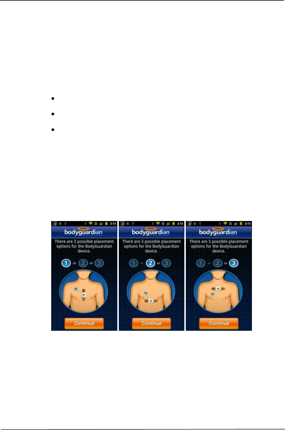
4.1.1 DISPOSABLE ADHESIVE ELECTRODES PATCH APPLICATION SITE
Attach the BodyGuardian Device at one of three positions on your chest. Your
healthcare provider will show you correct placement on your chest. Follow the
instructions carefully. Correct placement is very important to get accurate
readings from your heart.
T
4.1.2 PREPARING THE SKIN
The phase of preparing the body area on which placing the Bodyguardian Control
Unit, has an important role in establishing a good electric contact, thus allowing
the best kind of recording.
Here below the recommended procedure:
Figure 4-1 Preferred Bodyguardian Placement

BODYGUARDIAN CONTROL UNIT – BASE KIT Operator Manual
45
`
Prepare the skin area by cleaning with soap and water.
If hair is present, shave the area.
Make sure application area is dry with no lotion or cream applied.
4.1.3 PLACING THE DISPOSABLE ADHESIVE ELECTRODES PATCH
Follow the following instructions in order to correctly place the Bodyguardian
Control Unit.
1. Before removing the Bodyguardian Control Unit from its charging station,
ensure that the control unit is fully charged; the light LED 1 ( ) should
be OFF indicating a full charge.
2. Attach the Bodyguardian Control Unit to the four snaps on the Electrodes
Patch. Make sure all four snaps are connected; see Error! Reference
source not found.2.
Figure 4-2 Connecting Bodyguardian Control Unit to Electrodes Patch
3. Peel plastic off the back of the Electrodes Patch.
4. Ensure that the arrow on the Electrodes Patch points towards your left arm if
the patch is placed vertically (Error! Reference source not found.) or up
towards your head if placed horizontally (Error! Reference source not
found.).
5. Apply adhesive side of the Disposable adhesive electrodes patch to the skin
on the established placement (§ 4.1.1), and gently press.
NOTE
The Disposable adhesive electrodes patch should be comfortable when properly
positioned on the chest.

BODYGUARDIAN CONTROL UNIT – BASE KIT Operator Manual
46
4.2 OPERATIVE MODES
The Bodyguardian Control Unit can be configured to run in different operative
modes depending from the conditions (i.e. presence of Bluetooth connection with
an Associated Device, configuration settings received, etc.) as described below:
IDLE Mode: is when the Bodyguardian Control Unit is powered ON and it is
waiting to establish a Bluetooth pairing connection with the Associated Device.
ENGAGED Mode: is when the Bodyguardian Control Unit is powered ON,
waiting for a command from a paired Associated Device or a request for
pairing from a new Associated Device.
MONITORING Mode: is when the Bodyguardian Control Unit is powered
ON, gathering and storing in the internal memory data at the frequency
specified in the Configuration Settings, and sending the data as requested by
the Associated Device.
STREAMING Mode: is when the Bodyguardian Control Unit is powered ON
and sampling the data as specified in the Configuration Settings, sending them
directly to the Associated Device with periodicity specified by the last
configuration commands received from the Associated Device.
The two main operative modes which characterize the functionalities and intended
use of the device are Monitoring Mode and Streaming Mode.
4.2.1 MONITORING MODE
In monitoring mode the Bodyguardian Control Unit operates as a recorder of the
physiological data. The acquired signals are stored in the internal memory of the
device and works as an Holter. The data are sent from the Bodyguardian Control
Unit to the Associated Device according to the configuration parameters received
from the Associated Device during the configuration settings. The Associated
Device is responsible for forwarding the data to a remote storage server for later
analysis and evaluation.
In Monitoring Mode the Bodyguardian Control Unit can acquire and store the
following data, depending on the configuration received:
Raw Data
o ECG (128 or 256 Hz)
Derived values
o Activity level
o Body position values
o Breathing rate values
o Heart rate values
o Heart rate reliability
o RR interval variability
o Battery level

BODYGUARDIAN CONTROL UNIT – BASE KIT Operator Manual
47
`
The upload frequency depends on the Configuration Specifications. The
Bodyguardian Control Unit is equipped with an internal memory capable to store
up to 24 hours of data recording, enabling the device to work as an Holter
equipment.
4.2.2 STREAMING MODE
In Streaming mode the Bodyguardian Control Unit operates as an acquisition and
transmitter of the physiological data. The acquired signals are not stored in the
internal memory of the device but are sent directly from the Bodyguardian
Control Unit to the Associated Device according to the configuration parameters
received from the Associated Device during the configuration settings. The
Associated Device is responsible for forwarding the data to a remote storage
server for later analysis and evaluation.
In Streaming Mode the Bodyguardian Control Unit can acquire and transmit the
following data, depending on the configuration received:
Raw signals:
o ECG (128 or 256 Hz)
o 3-axis accelerometer (50 Hz)
o dZ bioimpedance (32 Hz)
o Z0 bioimpedance (32Hz)
Derived values:
o Heart rate values,
o Heart rate reliability,
o Breathing rate values,
o Activity level,
o RR interval variability,
o Body position values.
4.2.3 EVENT MONITORING
The Bodyguardian Control Unit has the capabilities to register symptomatic and
asymptomatic events during the functionalities.
Symptomatic Events recording: while wearing the Bodyguardian Control Unit
the user has the possibility to initiate an event recording, if is feeling symptoms
that suggest the need for further evaluation, by pressing the push button in the
middle of the device. The functionality is enabled either in Monitoring or
Streaming Modes. In case of symptomatic event button push, Bodyguardian
Control Unit will send a notification of the event to the Associated Device. If the
Associated Device is not available, the Bodyguardian Control Unit will retry
according to implementation and configuration requirement and eventually store
in the internal memory the undelivered notifications.
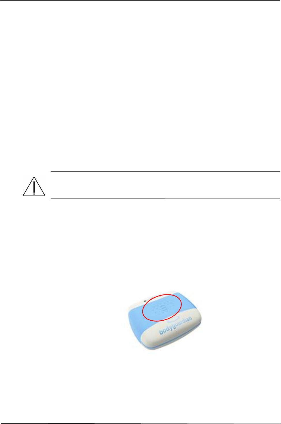
BODYGUARDIAN CONTROL UNIT – BASE KIT Operator Manual
48
Asymptomatic Events recording: while wearing the Bodyguardian Control Unit
some asymptomatic events can be recorded. Asymptomatic events occurs when
the values of physiological parameters detected violates the medical protocol
specified by the configured thresholds. In case of asymptomatic event detection
the Bodyguardian Control Unit will send a notification of the event to the
Associated Device. If the Associated Device is not available, the Bodyguardian
Control Unit shall retry according to the implementation and configuration
requirement and eventually store in the internal memory the undelivered
notifications.
4.3 INSTALLATION AND INSTRUCTIONS FOR THE PATIENT
The Bodyguardian Control Unit does not require specific installation procedure,
except for the configuration section which must be executed by the external
Associated Device. WARNING
In order to configure the Bodyguardian Control Unit and to know the software
details please refer to the indications contained in the User Manual provided by the
System Builder.
In order to turn ON the Bodyguardian Control Unit push the button area in the
middle of the device (Figure 4.4). The LED 2 and LED 3 will flash when it is
turned on. After the Bodyguardian Control Unit completes its initialization, the
middle led will flash green.
According to the configuration established, the Bodyguardian Control Unit will
start the data acquisition and transmission.
During the monitoring, if you want to mark a symptomatic event, press the push
button in the middle of the Bodyguardian Control Unit.
Figure 4-3 Bodyguardian Control Unit Push Button

BODYGUARDIAN CONTROL UNIT – BASE KIT Operator Manual
49
`
CHAPTER 5
MAINTENANCE
5.1 GENERAL INFORMATION ABOUT MAINTENANCE
In order to keep the Bodyguardian Control Unit working for a long time and to
ensure the patient’s and the operator’s safety, it is necessary that the general
checks indicated below are periodically performed by medical or paramedical
qualified staff or by technical staff authorized by Preventice.
Perform a sight inspection of all the components, the accessories, in order to
identify any traces of failure, damage, or disconnection.
Verify that all labels and any warning or instructions printed on the device are
readable.
Check that the performances of the device are correct.
Clean the external surface of the device carefully with the recommended
products only.
Replace parts or accessories only with those having the same characteristics or
expressly indicated by Preventice.
Discard replaced parts, accessories, and the device at its “end of life” according
to the local standards and directives currently in force.
For all ordinary maintenance operations pertaining to the components to which
the device is connected or auxiliary components not produced by Preventice such
as external Associated Device (Android smartphone or other), please refer to the
corresponding user’s manual provided with them.

BODYGUARDIAN CONTROL UNIT – BASE KIT Operator Manual
50
5.2 SAFETY CHECKS
It is essential to periodically check the equipment and the devices or systems it is
connected to and all the connections in order to ensure that the equipment
continues working efficiently and safely. It is also necessary to check the
equipment to remove any dust deposits. Preventive or corrective maintenance
operations must be performed by qualified technical staff expressly authorized by
Preventice.
A sight inspection of the interconnections, with particular care for the snaps
between equipment and the Disposable adhesive electrodes patch, can be
performed also by the user in order to remark any breaking or disconnection. In
case of need, immediately contact a qualified technician to solve the problem
detected before continuing to use the equipment or connecting it to other devices.
For the technical assistance request procedures, please refer to chapter “Request
for assistance” of this manual.
ATTENTION
Safety checks must be accurately performed periodically.
5.2.1 CONNECTORS
Check the connector on the Bodyguardian Control Unit for broken or damaged
contacts. If you find a damaged connector refer to qualified technical support
service.
5.2.2 BATTERY PACK
The rechargeable battery pack installed on the device is not accessible to the user
and its replacement should be performed only by qualified personnel expressly
authorized by Preventice. Anyway, you should consider the following general
warnings (e.g. in case of disposal of replaced parts with technical assistance).
• Do not let the ends of the battery pack come into contact with metal objects.
• Keep the battery pack away from heat or flames.
• Do not immerse the battery pack and avoid exposing it to rain or moisture.
• Avoid direct mechanical trauma to the battery pack.
• Do not attempt to disassemble, puncture, incinerate or short-circuit the battery.
These operations may cause a fire or emit toxic chemicals.
ATTENTION
When a battery is replaced, it cannot be reused and must be discarded according
to the standards and directives currently in force in the country where the
equipment is used.
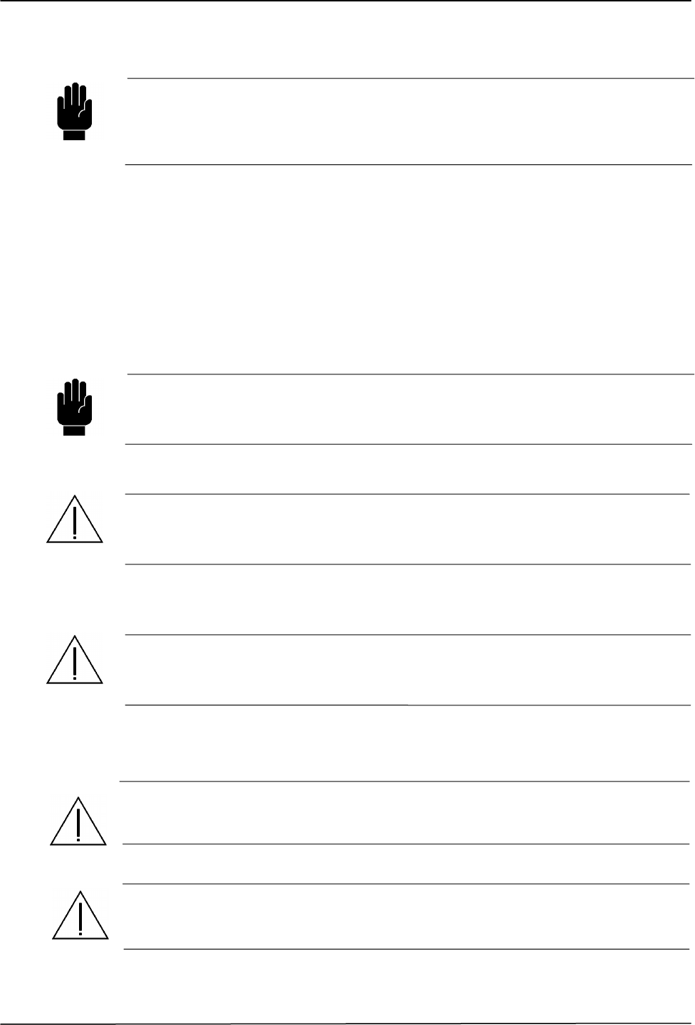
BODYGUARDIAN CONTROL UNIT – BASE KIT Operator Manual
51
`
WARNING
The state of battery charge is not guaranteed for inactivity periods longer than 1
month of storage at temperatures up to +45 ° C.
It is generally recommended to perform a cycle of discharge/charging the battery
after periods of inactivity.
5.3 CLEANING THE DEVICE
It is necessary to keep the equipment clean in order to avoid dust deposits, which
could interfere with the efficiency of all the system components.
It is possible to clean the equipment external surface with a cloth lightly
moistened with warm water and soap. Wipe the washed parts with a dry cloth.
WARNING
Do not immerse the equipment nor its parts in liquids, do not oil any part of it and
avoid cleaning the external surface with alcoholic disinfectants that could cause
damages and discoloration of the printed surfaces.
ATTENTION
Before cleaning any part of the equipment disconnect the equipment from the
power supply and disconnect the device from any other equipment or external
devices.
ATTENTION
Make sure no liquid seeps into the instrument and check it’s complete dryness
before to reconnect to the patient or before connecting it with other devices, thus
switching it on.
WARNING
Use Isopropyl Alcohol or equivalent products in order to disinfect the
BodyGuardian Control Unit, without immersing them into the liquids. Use products
according to directives and regulations of the country in which the device is used.
WARNING
All disposable (band-aid) must be destroyed after using them and cannot be used
again in any way. Please refer to the directives and regulations concerning
disposable requirements of the country in which the device is used.

BODYGUARDIAN CONTROL UNIT – BASE KIT Operator Manual
52
5.4 PARTICULAR WARNINGS FOR CRITICAL COMPONENTS
ATTENTION
The internal battery installed in the equipment cannot be accessed by the user and
its replacement must be performed only by qualified staff expressly authorized by
Preventice.
In every case please follow the general warnings listed below (for exemple in case
of discard of components replaced by servicing technicians).
Avoid terminal parts of the battery pack coming in contact with metal objects.
Keep the battery pack away from heat sources or flames.
Do not immerse the battery and avoid to exposure to rain or humidity.
Avoid directly hitting the battery.
Do not attempt to disassemble, burn or cause short-circuits to the battery. Such
operations may cause a fire or emission of toxic chemical substances.
In the event that electrolytes escape, make sure you do not touch it. Wash with
water for at least 15 minutes any body part that may have been in contact with it.
Should you experience any symptom after this period, ask for immediate medical
help.
ATTENTION
When a battery is replaced, it cannot be reused and must be discarded according
to the standards and directives currently in force in the country where the
equipment is used.

BODYGUARDIAN CONTROL UNIT – BASE KIT Operator Manual
53
`
CHAPTER 6
TECHNICAL CHARACTERISTICS
6.1 BODYGUARDIAN CONTROL UNIT
Product name Bodyguardian Control Unit
Description Active, non-invasive medical device
Intended use The Bodyguardian Control Unit is used for ambulatory
monitoring of non-lethal cardiac arrhythmias. Bodyguardian Control Unit is a
wearable electronic device that is worn on the chest. The device includes a
disposable fabric adhesive component that attaches to the subject and connects to
the enclosed electronic components.
The device will be worn intermittently or continuously for up to a 30-day period.
The recordings will be stored on the Bodyguardian Control Unit and transmitted
by the device via Bluetooth communication to an external Associated Device
(Android smartphone or other). The device is prescription only.
The Bodyguardian Control Unit recorder is intended to be used in a:
“Home Care” environment without clinicians’ surveillance.
“Clinic Care” environment with clinicians surveillance
Depending on the Environment, optional algorithms and/or thresholds (settable
via host software) can be used to generate measurements on an advisory basis for
patients. These are presented for:
Review and interpretation by the clinician, based upon knowledge of the
patient.
Results of the physical examination.
The data provided by the Bodyguardian Control Unit are exclusively intended to
be used by trained medical personnel to assist patients that require monitoring of
physiological parameters with reference of the followings context:
Screening of patients with symptoms suggesting arrhythmia over a
minimum 24-hour period.
Screening and off line evaluation of HR and Breath variability if the nature
of this variability cannot determine a Life-threatening for the patient.
Not intended to allow direct diagnosis or monitoring of vital physiological
processes parameters (for instance cardiachearth rate, respiration), where
the nature of variations is such that it could result in immediate danger to
the patient.
Not intended for therapeutic purpose.

BODYGUARDIAN CONTROL UNIT – BASE KIT Operator Manual
54
The “Body Guardian” Control Unit is intended from adult without race exclusion.
Patient with implanted device are excluded to wear this
device.
Applied Standards
Standard
Edition /
year
Description
IEC 60601-1
Ed. 2 + A1 + A2
+ Deviation
UL/CSA
Medical Electrical Equipment – General requirement for safety
IEC 60601-1-1
Ed. 2
Collateral standard: Safety requirements for medical electrical systems
IEC 60601-1-2
Ed. 2 + A1
Collateral standard: Electromagnetic compatibility
Requirements and tests
IEC 60601-1-4
Ed. 1
Collateral standard: Programmable electrical medical systems
IEC 60601-1-6
Ed. 1
Collateral standard: Usability
IEC 60601-2-47
Ed. 1
Particular requirements for the safety, including essential performance,
of ambulatory electrocardiographic systems
IEC 60601-2-49
Ed 1 + Ec1
Particular requirements for the safety of multifunction patient
monitoring equipment
IEC 60529
Ed. 2 + A1
Degrees of protection provided by enclosures (IP Code)
EC38
2007
Particular requirements for the safety, including essential
performance, of ambulatory electrocardiographic systems
EC57
Ed. 2
Testing and reporting performance results of cardiac rhythm
and ST-segment measurement algorithms
UL 60601-1
Ed. 1
Safety of Medical Electrical Equipment Part 1 – General requirements
for Safety
CAN/CSA C22.2
Ed. 2 + A1 + A2
Medical Electrical Equipment Part 1 – General requirements for Safety
Type of protection against electric shocks
Internal powered equipment.
Protection level against electrical direct and indirect contacts
BF type (patient inputs)
Protection level against inflow of solids and liquids
IPX4 Device protected against
Operational mode Continuous, within the specified limits
Environmental conditions for usage
- Temperature: from +10°C to +45°C
- Relative humidity: from 10% to 95% RH
- Atmospheric pressure: from 700hPA to 1060hPA
Environmental conditions for storage (max. 15 weeks )

BODYGUARDIAN CONTROL UNIT – BASE KIT Operator Manual
55
`
- Temperature: from -30°C to +60°C
- Relative humidity: from 5% to 95% RH
(excluding condensation)
- Atmospheric pressure: from 500hPA to 1060hPA
External dimensions and weight
Height: ~ 17 mm
Width: ~ 60 mm
Depth: ~ 50 mm
Max Weight: ~ 35 g
Case Material: PC Polycarbonate
Battery Capacity 350 mAh min, 380 mAh typical, 1.5Wh
Battery Charger Input Power
Requirement 100-240 VAC, 50-60 Hz,
Battery Charger Output Power
Requirement 6 VDC, 200mA,
Battery Life 500 Cycles > 70% of initial
capacity
Battery Voltage 3.7V
ECG
Sampling Rate 128/256 Hz
Digital Resolution 12 bit
Input Dynamic Range ± 10 mV
Input Offset Dynamic Range ± 300 mV
Bio Impedance
Bio-impedance injection 100µA @ 50KHz
Bio-impedance sampling 32/second
Impedance 0 to 120 Ohms
Maximum allowed Load 7KOhms
Accelerometer
Accelerometer activity sampling 50/second

BODYGUARDIAN CONTROL UNIT – BASE KIT Operator Manual
56
Accelerometer 3 axis 12-bit
Sampling Rate
ECG 128/256 Hz
Impedance 32 Hz
Accelerometer 50 Hz
Measurement Ranges
Heart Rate 25 to 240 BPM
Respiration 0 to 30 BrPM
Posture ± 2g range in x,y,z direction
Data Storage
Capacity 24 hours continuous recording
Type Internal NAND Flash
Communication Means Bluetooth communication between
Bodyguardian Control Unit and
Smatphone
Communication Frequency 2.4 GHz
Electrode connections - 4 ECG snaps connectors
Other interface - 1 yellow Led for Device Charging Status
- 1 green Led for Device Operative Mode Status
- 1 yellow Led for special Events occurrences
- 1 multifunction push button
Power supply Battery powered (Rechargeable built-in
Lithium Battery)
Absorption during Recharging <600mW
6.2 DISPOSABLE ADHESIVE ELECTRODES PATCH
The characteristics specification of this component is responsibility of the System Builder

BODYGUARDIAN CONTROL UNIT – BASE KIT Operator Manual
57
`
6.3 AC/DC MEDICAL POWER SUPPLY
6.3.1 OPTION 1
Manufacturer FRIWO
Model AC/DC ADAPTER FW7662M/06
Input 100-240 VAC – 50-60 Hz
Output 5.9VDC @ 1A
Safety standards Fulfils Class II SELV for
IEC 60601-1, UL 2601, VDE, CE label, SIQ,
Fulfill medical application class B / BF / CF
Electrical protection level Class II
Case Material: Plastic
Dimensions: 52 x 52 x 35.5 mm
6.4 BODYGUARDIAN CHARGING CRADLE
Input/Output Operative 5.9VDC nominal. Connection with
specified AC/DC adapter (model FRIWO
FW7662M/06)
Input connector THT POWER SUPPLAY JACK 4,4mm
opening diameter p/n 1613_05
Output connector Spring-Loaded Contacts Pins
Case Material: PC Policarbonate
Dimensions: 63 x 54 x 21 mm
Operational mode Continuous, within the specified limits
Environmental conditions for usage
- Temperature: from +10°C to +45°C
- Relative humidity: from 10% to 95% RH
- Atmospheric pressure: from 700hPA to 1060hPA
Environmental conditions for storage (max. 6 months)
- Temperature: from -30°C to +60°C
- Relative humidity: from 5% to 95% RH
(excluding condensation)
- Atmospheric pressure: from 500hPA to 1060hPA

BODYGUARDIAN CONTROL UNIT – BASE KIT Operator Manual
58
CHAPTER 7
REQUEST FOR ASSISTANCE
7.1 OBTAINING SERVICE
In case of problems such as failure of the device or anyway in case of partial or
incorrect working that cannot be solved through usual maintenance operations,
please contact one of the main offices or branches of Preventice or the nearest
retailer or authorized servicing center.
ATTENTION
In case of failure of the device or if it starts working in a way not complying with
what is written in the manual, especially as far as safety is concerned, STOP USING
IT IMMEDIATELY and contact the technical service. Do not use the device until the
safety conditions have been checked and restored.
NOTE
In order to speed up the procedures to start the intervention of the technical
service and to make it easier for the specialized technical staff to identify the
problem on the first phone call by the customer, please fill in the form below in this
page.
The equipment data may be found on the equipment identification label.
REQUEST FOR ASSISTANCE
Preventice Device/system name.....................................................................................
Preventice Device code/reference number (REF) .......................................................
Serial number (SN) or lot number (LOT) ....................................................................
Current software version (Rel) ....................................................................................

BODYGUARDIAN CONTROL UNIT – BASE KIT Operator Manual
59
`
7.2 PREVENTICE MAIN OFFICES
OPERATING OFFICES
PREVENTICE
1652 Greenview Drive SW
Rochester, MN 55902
Phone 800-509-0503
Fax 507-281-3630
Website www.preventice.com
Any other authorized assistance center or Technical assistance numbers.