ST Microelectronics S R L STILE01 RF BT4.1 User Manual 1
ST Microelectronics S.R.L. RF BT4.1 1
User Manual

May 2016
DocID029208 Rev 2
1/37
www.st.com
User manual
Getting started with the software package for Bluetooth low
energy and sensors in BLUEMICROSYSTEM2
Introduction
The BLUEMICROSYSTEM2 expansion software package for STM32Cube lets you read and display
real-time environmental sensor data, digital microphone levels and acoustic source localization
information with a dedicated Android™/iOS™ application.
The package implements application level functions based on the Bluetooth low energy protocol and
enables communication with Android/iOS devices. Developers can use it to prototype applications with
Android/iOS services, and transmit real-time sensor data with ease.
The software runs on the STM32 microcontroller and includes drivers that recognize the Bluetooth low
energy (BlueNRG) hardware, the four sensor devices and 2 MEMS microphones. The expansion is built
on the STM32Cube framework for STM32 microcontrollers and comes with a sample implementation to
kick-start development.
STEVAL-STLKT01V1

Contents
STEVAL-STLKT01V1
2/37
DocID029208 Rev 2
Contents
1 BLUEMICROSYSTEM2 software description ................................ 5
1.1 Overview ........................................................................................... 5
1.2 Architecture ....................................................................................... 6
1.3 Folder structure ................................................................................. 7
1.4 APIs .................................................................................................. 8
1.5 Sample application description .......................................................... 8
1.6 Android and iOS sample client application ...................................... 11
2 System setup guide ....................................................................... 26
2.1 Hardware description ...................................................................... 26
2.1.1 STM32 Nucleo platform .................................................................... 26
2.1.2 X-NUCLEO-CCA02M1 expansion board ......................................... 26
2.1.3 X-NUCLEO-IDB04A1 expansion board............................................ 27
2.1.4 X-NUCLEO-IDB05A1 expansion board............................................ 28
2.1.5 X-NUCLEO-IKS01A1 expansion board ............................................ 29
2.2 Software description ........................................................................ 30
2.3 Hardware and software setup ......................................................... 31
2.3.1 Hardware setup ................................................................................ 31
2.3.2 Software setup .................................................................................. 31
2.3.3 System setup guide .......................................................................... 31
3 Revision history ............................................................................ 36

STDK-STILECS01V1
List of tables
DocID029208 Rev 2
3/37
List of tables
Table 1: Document revision history .......................................................................................................... 36

List of figures
STEVAL-STLKT01V1
4/37
DocID029208 Rev 2
List of figures
Figure 1: BLUEMICROSYSTEM2 software architecture ............................................................................ 7
Figure 2: BLUEMICROSYSTEM2 package folder structure ....................................................................... 7
Figure 3: Terminal setting ........................................................................................................................... 8
Figure 4: Initialization phase ....................................................................................................................... 9
Figure 5: UART console output when one device is connected to the board........................................... 11
Figure 6: BlueMS (Android version) initial page after BLE connection ..................................................... 12
Figure 7: BlueMS (Android version) osxMotionFX sensor fusion page .................................................... 13
Figure 8: BlueMS (Android version) popup windows ................................................................................ 14
Figure 9: BlueMS (Android version) mic level plot .................................................................................... 15
Figure 10: BlueMS (Android version) accelerometer plot ......................................................................... 16
Figure 11: BlueMS (Android version) menu selection .............................................................................. 17
Figure 12: BlueMS (Android version) Serial console (stdout/stderr) ........................................................ 18
Figure 13: BlueMS (Android version) Debug console (stdin/stdout/stderr) .............................................. 19
Figure 14: BlueMS (Android version) LSM6DS3 DIL24 hardware features ............................................. 20
Figure 15: BlueMS (Android version) LSM6DS3 DIL24 examples: pedometer, wake up, orientation,
double tap. ................................................................................................................................................ 21
Figure 16: BlueMS (Android version) osxMotionAR activity recognition page ......................................... 22
Figure 17: BlueMS (Android version) osxMotionCP carry position recognition page ............................... 23
Figure 18: BlueMS (Android version) osxMotionGR gesture recognition page ........................................ 24
Figure 19: BlueMS (Android version) example of audio source localization plot value ............................ 25
Figure 20: STM32 Nucleo board ............................................................................................................... 26
Figure 21: X-NUCLEO-CCA02M1 board .................................................................................................. 27
Figure 22: X-NUCLEO-IDB04A1 expansion board ................................................................................... 28
Figure 23: X-NUCLEO-IDB05A1 expansion board ................................................................................... 29
Figure 24: X-NUCLEO-IKS01A1 board .................................................................................................... 30
Figure 25: LSM6DS3 DIL24 adapter board .............................................................................................. 30
Figure 26: STM32 Nucleo plus X-NUCLEO-CCA02M1 boards ............................................................... 32
Figure 27: STM32 Nucleo plus X-NUCLEO-CCA02M1 plus X-NUCLEO-IDB04A1 boards .................... 32
Figure 28: STM32 Nucleo plus X-NUCLEO-CCA02M1 plus X-NUCLEO-IDB04A1 plus X-NUCLEO-
IKS01A1 plus LSM6DS3 DIL24 boards .................................................................................................... 33
Figure 29: Resistors to remove from X-NUCLEO-IKS01A1 board ........................................................... 34
Figure 30: Solder bridges to close on X-NUCLEO-CCA02M1 board (when using NUCLEO-L476RG
board) ........................................................................................................................................................ 35

STEVAL-STLKT01V1
BLUEMICROSYSTEM2 software description
DocID029208 Rev 2
5/37
1 BLUEMICROSYSTEM2 software description
1.1 Overview
The key features of the BLUEMICROSYSTEM2 package are:
Complete middleware to build applications using temperature and humidity sensors
(HTS221), pressure sensor (LPS25HB), motion sensors (LIS3MDL and LSM6DS0)
and microphone sensor (2x MP34DT01-M)
Compatible with the motion sensor LSM6DS3 DIL24 expansion component
Very low power Bluetooth low energy (BlueNRG) single-mode network processor for
transmitting information to one client.
osxMotionFX (iNEMOEngine PRO) real-time motion sensor data fusion (under
OPEN.MEMS license) to combine the output from multiple MEMS sensors.
Accelerometer-only algorithms:
osxMotionAR (iNEMOEngine PRO) real- time activity-recognition algorithm
(under OPEN.MEMS license)
osxMotionCP (iNEMOEngine PRO) real-time carry-position recognition algorithm
(under OPEN.MEMS license)
osxMotionGR (iNEMOEngine PRO) real- time gesture recognition algorithm
(under OPEN.MEMS license)
osxAcousticSL Real-time sound source localization software expansion (under
OpenSoftwareX license) based on two or four digital microphone audio signals.
Based on common STM32Cube framework
BlueMS compatible application for Android/iOS (version 2.0.0 or above) for visualizing
information sent via Bluetooth.
Free, user-friendly license terms
Sample implementation available on X-NUCLEO-CCA02M1, X-NUCLEO-IKS01A1
and X-NUCLEO-IDB04A1 or X-NUCLEO-IDB05A1 boards when connected to a
NUCLEO-F401RE or NUCLEO-L476RG board.
This software creates the following Bluetooth services:
1. The first service exposes all the hardware features with the following characteristics:
Temperature
Pressure
Humidity
3D gyroscope, 3D magnetometer, 3D accelerometer
Microphones dB noise level.
2. The second service exposes the software characteristics:
the quaternions generated by the osXMotionFX library in short precision
the activity recognized using the osxMotionAR algorithm
the carry position recognized using the osxMotionCP algorithm
the gesture recognized using the osxMotionGR algorithm
the audio source localization (for only F4 STM32 Nucleo motherboard) using the
osxAcousticSL algorithm
3. The third service exposes the Console service with:
stdin/stdout for bi-directional communication between client and server
stderr for a mono-directional channel from the STM32 Nucleo board to an
Android/iOS device
4. The last service is for transmitting/resetting the calibration status and enabling the
following LSM6DS3 DIL24 expansion hardware features when it is mounted:
Pedometer

BLUEMICROSYSTEM2 software description
STEVAL-STLKT01V1
6/37
DocID029208 Rev 2
Free Fall detection
Single tap detection
Double tap detection
Wake up detection
Tilt detection
3D orientation
This software gathers the temperature, humidity, pressure, audio and motion sensors
drivers for the HTS221, LPS25H, MP34DT01-M, LSM6DS0 (or LSM6DS3) and LIS3MDL
devices, running on STM32.
This package is compatible with the BlueMS Android/iOS (Version 2.0.0 or higher)
application available at respective Play/iTunes stores, which can be used for displaying
information sent via the Bluetooth low energy protocol. To use the hardware features of the
LSM6DS3 DIL24 device, use BlueMS Android/iOS application version 2.2.0 or higher.
1.2 Architecture
The software is based on the STM32CubeHAL hardware abstraction layer for the STM32
microcontroller.
The package provides a Board Support Package (BSP) for the sensors expansion board
and middleware components for serial communication with a PC.
To access and use the sensor expansion board, the application software uses:
STM32Cube HAL layer: provides a simple, generic and multi-instance set of generic
and extension APIs (application programming interfaces) to interact with the upper
layer application, libraries and stacks. It is directly based on a generic architecture and
allows the layers that are built on it, such as the middleware layer, to implement their
functions without requiring the specific hardware configuration for a given
microcontroller unit (MCU). This structure improves library code reusability and
guarantees easy portability across other devices.
Board support package (BSP) layer: supports the peripherals on the STM32 Nucleo
board (except the MCU) with a limited set of APIs providing a programming interface
for certain board-specific peripherals like the LED, the user button, etc., and helps
determine the specific board version. For the sensor expansion board, it provides the
programming interface for various inertial and environmental sensors and support for
initializing and reading sensor data.
STEVAL-STLKT01V1
BLUEMICROSYSTEM2 software description
DocID029208 Rev 2
7/37
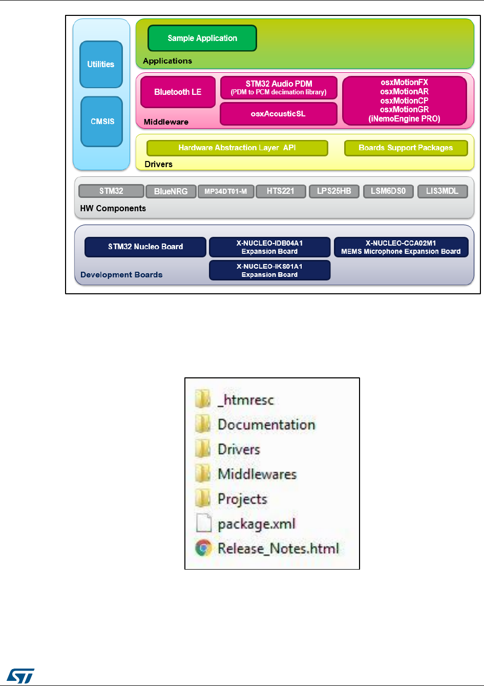
Figure 1: BLUEMICROSYSTEM2 software architecture
1.3 Folder structure
This section provides an overview of the package folders structure.
The next figure outlines the architecture of the package
Figure 2: BLUEMICROSYSTEM2 package folder structure
The following folders are included in the software package:
Documentation: contains a compiled HTML file generated from the source code,
which details the software components and APIs.
Drivers: contains the HAL drivers, the board-specific drivers for each supported board
or hardware platform, including the on-board components, and the CMSIS vendor-
independent hardware abstraction layer for the Cortex-M processor series.
BLUEMICROSYSTEM2 software description
STEVAL-STLKT01V1
8/37
DocID029208 Rev 2
Middlewares: contains libraries and protocols for BlueNRG Bluetooth low energy,
osx.MotionFX (iNEMOEngine PRO) sensors fusion library, osx.MotionAR
(iNEMOEngine PRO) activity-recognition library, osx.MotionCP (iNEMOEngine PRO)
carry-position recognition library, osx.MotionGR (iNEMOEngine PRO) gesture
recognition library and osx.AcousticSL sound source localization library.
Projects: contains a sample application used for transmitting the output of the sensor
data and of the osx.MotionFX sensor fusion, osx.MotionAR activity-recognition,
osx.MotionCP carry-position, osx.MotionGR gesture recognition and osx.AcousticSL
sound source localization libraries by using the Bluetooth low energy protocol provided
for the NUCLEO-F401RE/NUCLEO-L476RG platforms through the IAR Embedded
Workbench for ARM, RealView Microcontroller Development Kit (MDK-ARM) and
System Workbench for STM32 development environments.
1.4 APIs
Detailed user-API technical information with full function and parameter descriptions is
available in a compiled HTML file in the package “Documentation” folder.
1.5 Sample application description
A sample application using the X-NUCLEO-IKS01A1, X-NUCLEO-CCA02M1 and X-
NUCLEO-IDB04A1 or X-NUCLEO-IDB05A1 expansion boards with the NUCLEO-F401RE
or NUCLEO-L476RG board is provided in the “Projects” directory. Ready to build projects
are available for multiple IDEs.
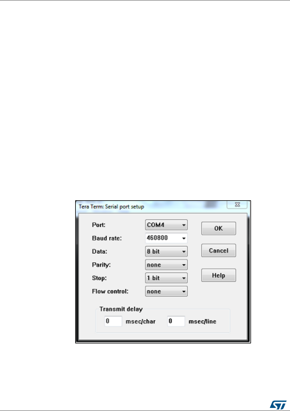
Application behavior can be controlled via UART with a terminal application and the
following settings for the appropriate port.
Figure 3: Terminal setting
When you first press the reset button, the application:
starts initializing the UART, I²C and SPI interfaces
creates a random BLE MAC address and a random connection PIN necessary for
making the connection
initializes the BLE hardware service adding the temperature, humidity, pressure, 3D
gyroscope, 3D magnetometer, 3D accelerometer and microphone characteristics
STDK-STILECS01V1
BLUEMICROSYSTEM2 software description
DocID029208 Rev 2
9/37
initializes the BLE SW service adding the osx.MotionFX, osx.MotionAR,
osx.MotionCP, osx.MotionGR and osx.AcousticSL libraries.
initializes the BLE console service adding the stdin/stdout and stderr characteristics
initializes the BLE config service transmitting/resetting the calibration status and
enabling the LSM6DS3 DIL24 hardware features (if present).
checks whether the LSM6DS3 DIL24 extension is present.
Checks whether all the sensors are present and working.
controls whether the osxMotionFX, osxMotionAR, osxMotionCP, osxMotionGR and
osxAcousticSL libraries have been initialized properly with valid licenses.
determines which BlueNRG expansion board is connected to the STM32 Nucleo
board (X-NUCLEO-IDB04A1 or X-NUCLEO-IDB05A1) and hardware and firmware
version information.
If the LSM6DS3 DIL24 extension is present, the system is able also to understand a free
fall situation because the DS3 generates one interrupts when there is free fall situation.
This situations is transmitted over Bluetooth to the attached Android™/iOS™ device.
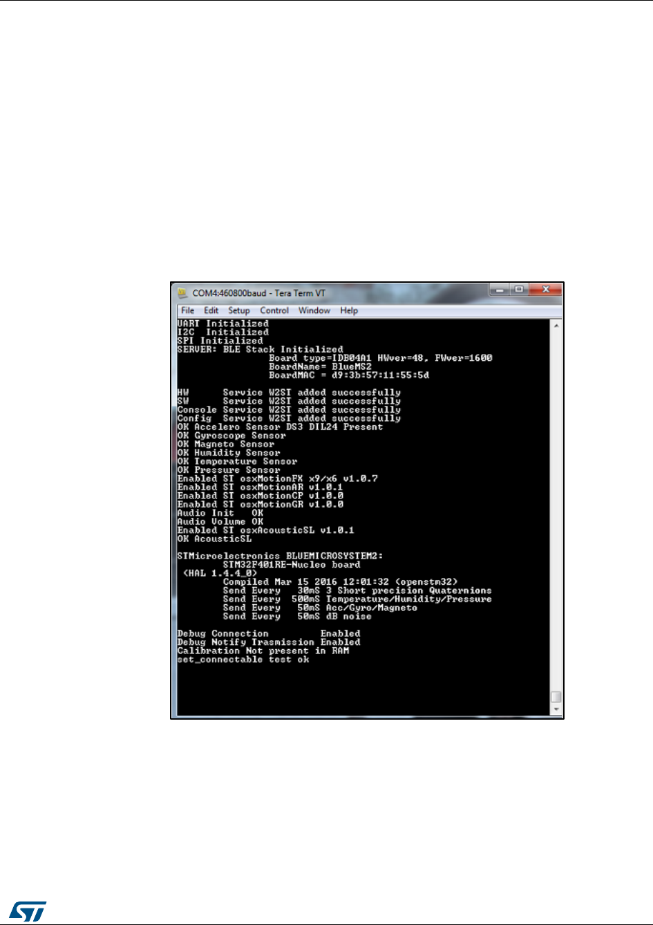
Figure 4: Initialization phase
As shown in the console output above, the application sends:
3 short precision quaternions every 30ms
Temperature/Humidity/Pressure data every 500ms
3D Accelerometer, 3D Gyroscope and 3D Magnetometer data every 50ms
signal noise microphone levels every 50ms
This application reads the accelerometer, magnetometer and gyroscope values at 100
samples/second. The osxMotionFX (iNEMOEngine PRO) library combines these sensor
values to produce and transmit 100 quaternions/second to the client connected via
Bluetooth low energy to reflect real motion using a vendor-specific BLE service.

BLUEMICROSYSTEM2 software description
STEVAL-STLKT01V1
10/37
DocID029208 Rev 2
These definitions in osx_bms_config.h control how many quaternions the application sends
to the Bluetooth client:
QUAT_UPDATE_MUL_10MS: defines the transmission rate for each set of quaternions
by multiple of 10 ms.
SEND_N_QUATERNIONS: defines how many quaternions are sent on each Bluetooth
package.
By default, the application sends 3 quaternions every 30 ms.
The same osx_bms_config.h file also defines:
ENV_UPDATE_MUL_10MS the transmission rate for Temperature/Pressure and
Humidity/Lux
ACC_GYRO_MAG_UPDATE_MUL_10MS the transmission rate for Acc/Gyro and
Magneto values
OSX_BMS_DEBUG_CONNECTION and OSX_BMS_DEBUG_NOTIFY_TRAMISSION to
enable some debugging information for BLE communication
OSX_BMS_MOTIONAR to enable the osxMotionAR activity recognition algorithm
OSX_BMS_MOTIONCP to enable the osxMotionCP carry position recognition algorithm
OSX_BMS_MOTIONGR to enable the osxMotionGR gesture recognition algorithm
OSX_BMS_ACOUSTIC_MIC_ANGLE to enable the osxAcousticSL audio source
localization algorithm (only NUCLEO-F401R Nucleo board)
The osxMotionFX (INEMOEngine PRO) library has an autocalibrating procedure and the
calibration status is transmitted via BLE to the client. By pressing the user button on the
NUCLEO-F401RE (or NUCLEO-L476RG) board, it is possible to reset the library
calibration status, thereby forcing a new autocalibration procedure.
The osxMotionAR (INEMOEngine PRO) library is able to recognize the following activities:
Stationary
Walking
fast walking
jogging
biking
driving
The osxMotionAR can be enabled via the OSX_BMS_MOTIONAR define in
osx_bms_config.h.
The osxMotionCP (INEMOEngine PRO) library recognizes and provides real-time
information about how the user is carrying the board, which equates to the phone carry
position:
on desk
in hand
near head
shirt pocket
trouser pocket
arm swing
The osxMotionCP can be enabled via the OSX_BMS_MOTIONCP define in
osx_bms_config.h.
The osxMotionGR (INEMOEngine PRO) library is able to recognize gestures like:
pick up
glance
wake up in hand
STEVAL-STLKT01V1
BLUEMICROSYSTEM2 software description
DocID029208 Rev 2
11/37
The osxMotionGR can be enabled via the OSX_BMS_MOTIONGR define in
osx_bms_config.h.
The osxAcousticSL library is able to localize the audio sound source using the data
acquired from the microphones. It can be enabled via the
OSX_BMS_ACOUSTIC_MIC_ANGLE define in osx_bms_config.h.
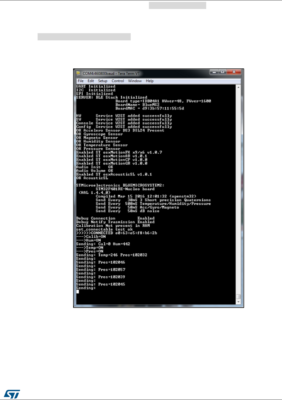
When an Android/iOS device is connected to the board, it is possible to control what the
board transmit (see the following figure).
Figure 5: UART console output when one device is connected to the board
1.6 Android and iOS sample client application
The BLUEMICROSYSTEM2 software for STM32Cube is compatible with the BlueMS
Android/iOS applications (Version 2.0.0 or higher) available at the respective Play/iOS
stores. The LSM6DS3 DIL24 hardware features are only visible with BlueMS Android/iOS
version 2.2.0 or higher.
We will use Android application to demonstrate how it works.
BLUEMICROSYSTEM2 software description
STEVAL-STLKT01V1
12/37
DocID029208 Rev 2
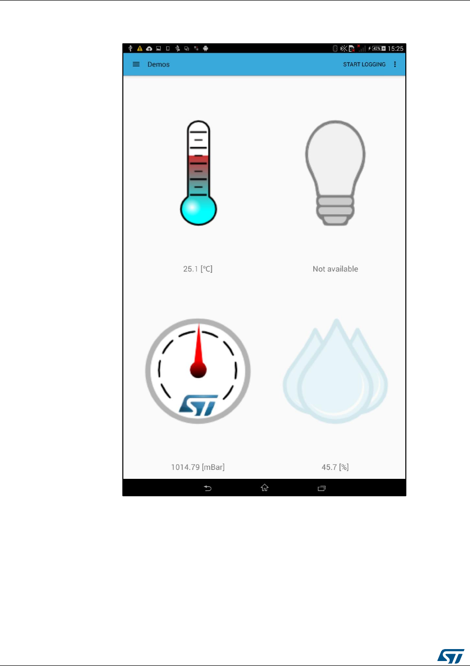
Following connection, BlueMS starts with the main page shown below, where the values of
temperature, pressure and humidity are displayed.
Figure 6: BlueMS (Android version) initial page after BLE connection
STEVAL-STLKT01V1
BLUEMICROSYSTEM2 software description
DocID029208 Rev 2
13/37
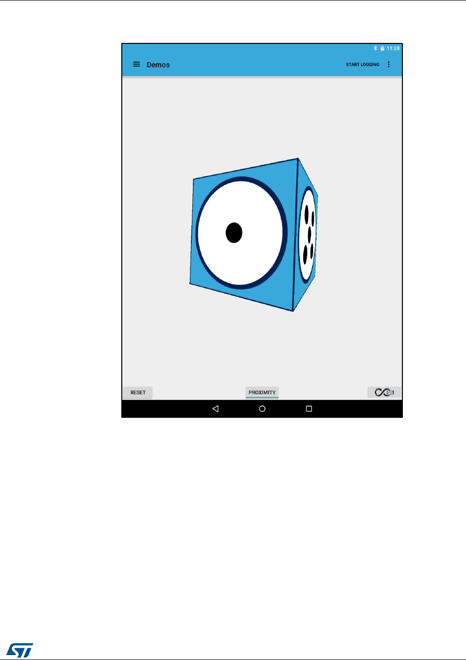
As shown below, the next page depicts the osxMotionFX sensor fusion library output with a
cube that rotates with board movement.
Figure 7: BlueMS (Android version) osxMotionFX sensor fusion page
On this page there are two buttons along the bottom:
the left is for resetting the cube position.
the right shows the calibration status of the osxMotionFX Library (black for not
calibrated, green for calibrated). Clicking it forces a magneto calibration.
BLUEMICROSYSTEM2 software description
STEVAL-STLKT01V1
14/37
DocID029208 Rev 2
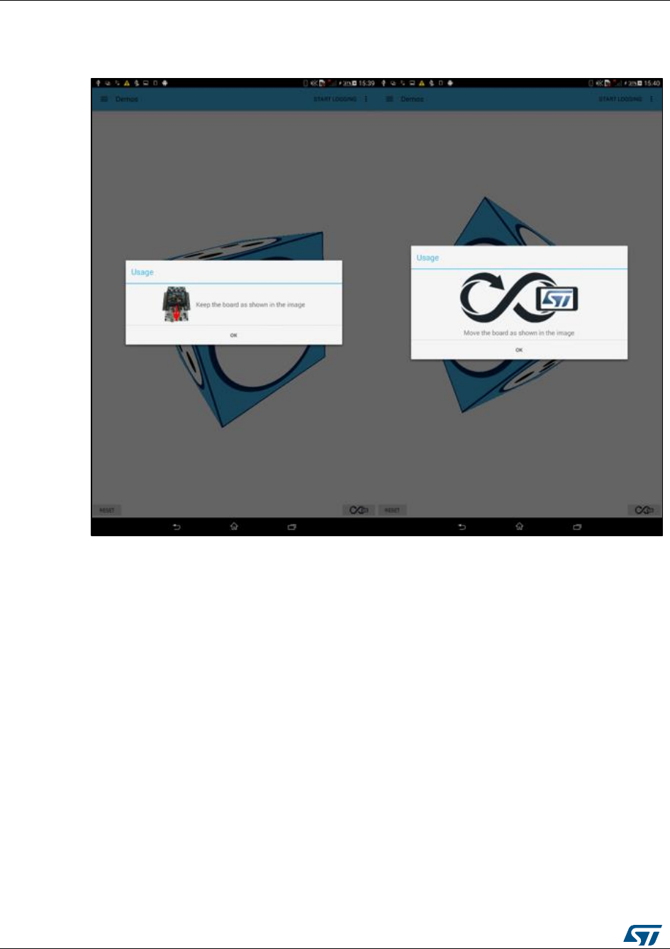
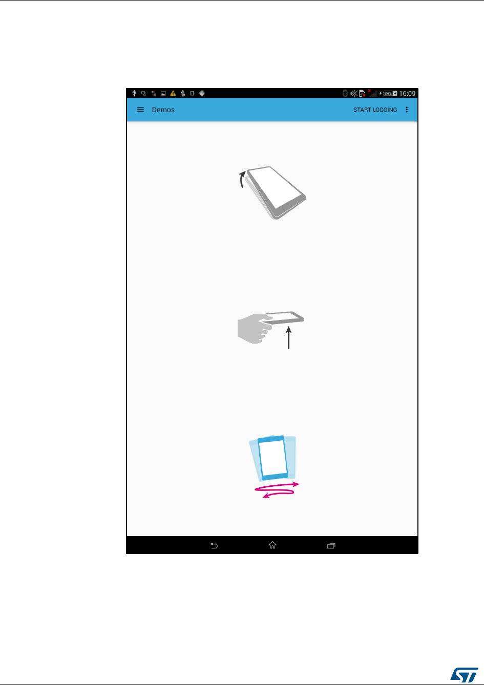
When either button is pressed, the application pops up a window describing how to position
the board for correct cube rotation and how to move the board to facilitate calibration (see
below)
Figure 8: BlueMS (Android version) popup windows
STEVAL-STLKT01V1
BLUEMICROSYSTEM2 software description
DocID029208 Rev 2
15/37
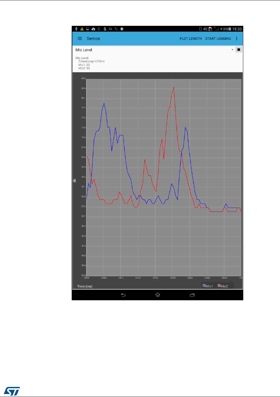
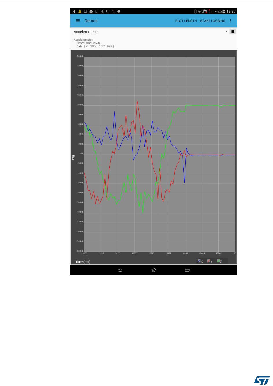
On the next left page, you can plot sensor data from the sensors expansion boards, as
shown in the following figures.
Figure 9: BlueMS (Android version) mic level plot
BLUEMICROSYSTEM2 software description
STEVAL-STLKT01V1
16/37
DocID029208 Rev 2
Figure 10: BlueMS (Android version) accelerometer plot
STDK-STILECS01V1
BLUEMICROSYSTEM2 software description
DocID029208 Rev 2
17/37
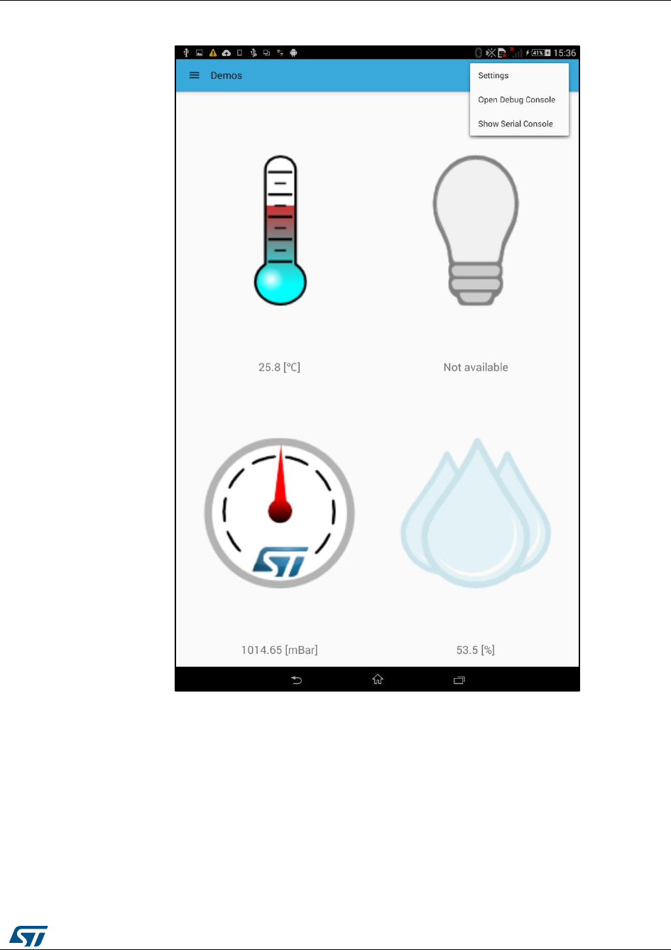
In the option menu below, you can enable the Serial or Debug (with stdin) console.
Figure 11: BlueMS (Android version) menu selection
BLUEMICROSYSTEM2 software description
STEVAL-STLKT01V1
18/37
DocID029208 Rev 2
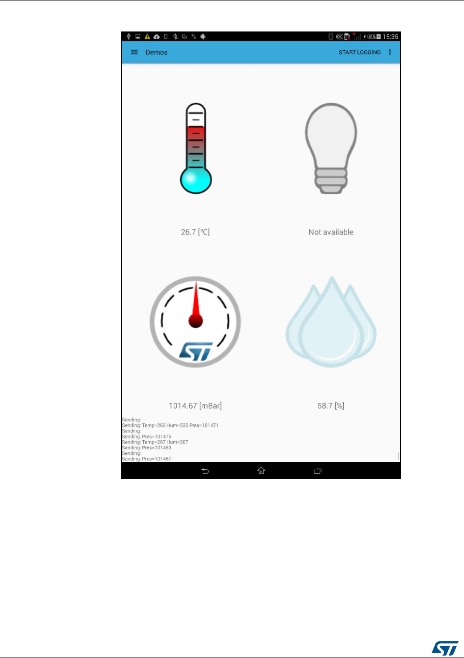
If the Serial console is enabled, stdout/stderr is displayed, as shown below.
Figure 12: BlueMS (Android version) Serial console (stdout/stderr)
STEVAL-STLKT01V1
BLUEMICROSYSTEM2 software description
DocID029208 Rev 2
19/37
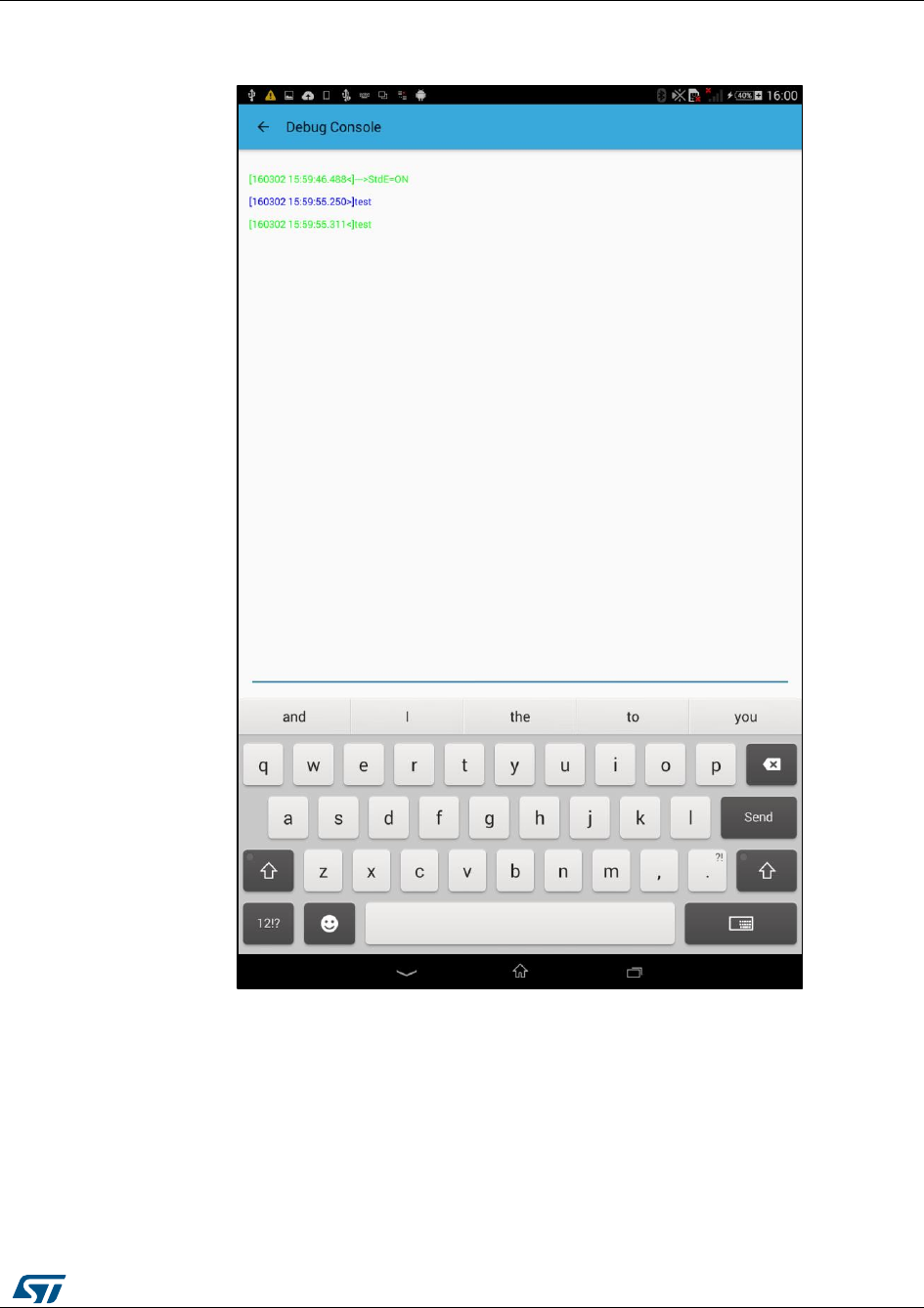
If the Debug console is enabled, stdin is displayed and any message written in the Debug
console triggers a relpy with the same message, as shown below.
Figure 13: BlueMS (Android version) Debug console (stdin/stdout/stderr)
BLUEMICROSYSTEM2 software description
STEVAL-STLKT01V1
20/37
DocID029208 Rev 2
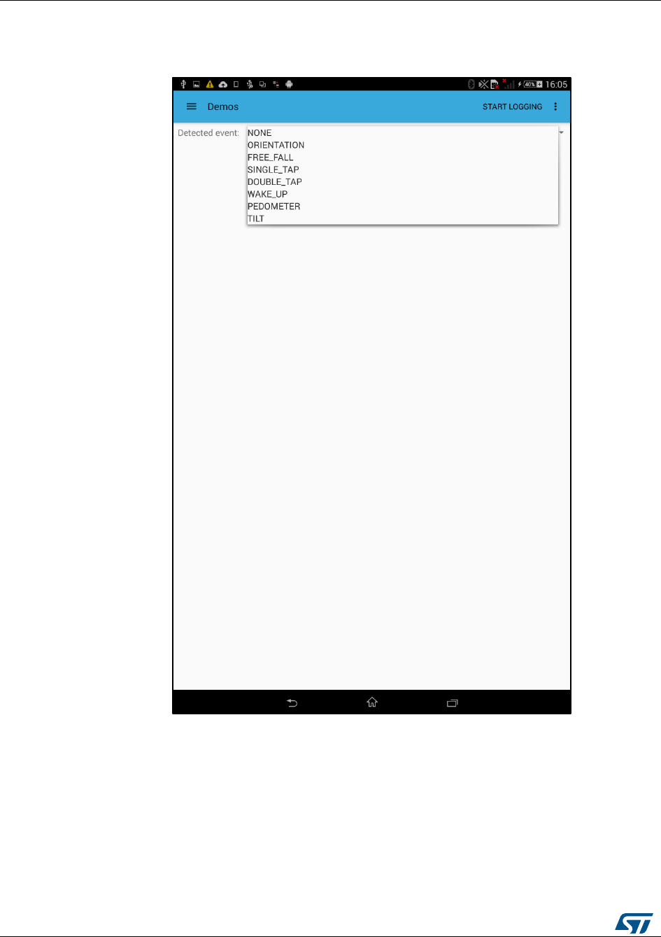
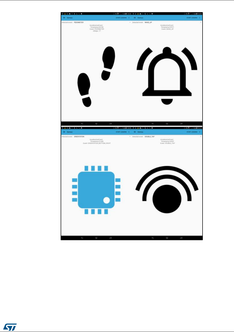
If the LSM6DS3 DIL24 is present, there is another page where you can choose which
hardware feature to enable (one at the time) and view the events from the LSM6DS3 DIL24
(see following figures) on the same page.
Figure 14: BlueMS (Android version) LSM6DS3 DIL24 hardware features
STEVAL-STLKT01V1 BLUEMICROSYSTEM2 software description
DocID029208 Rev 2
21/37
Figure 15: BlueMS (Android version) LSM6DS3 DIL24 examples: pedometer, wake up,
orientation, double tap.
BLUEMICROSYSTEM2 software description
STEVAL-STLKT01V1
22/37
DocID029208 Rev 2
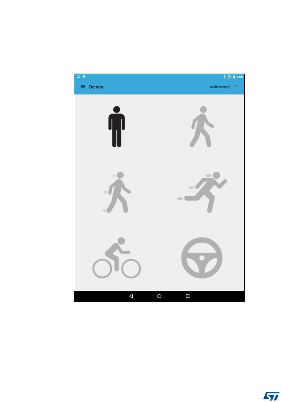
If the osxMotionAR algorithm is enabled, the page shown below is available, signaling one
of the following recognized activities:
Stationary
Walking
Fast walking
Jogging
Biking
Driving
Figure 16: BlueMS (Android version) osxMotionAR activity recognition page
STEVAL-STLKT01V1
BLUEMICROSYSTEM2 software description
DocID029208 Rev 2
23/37
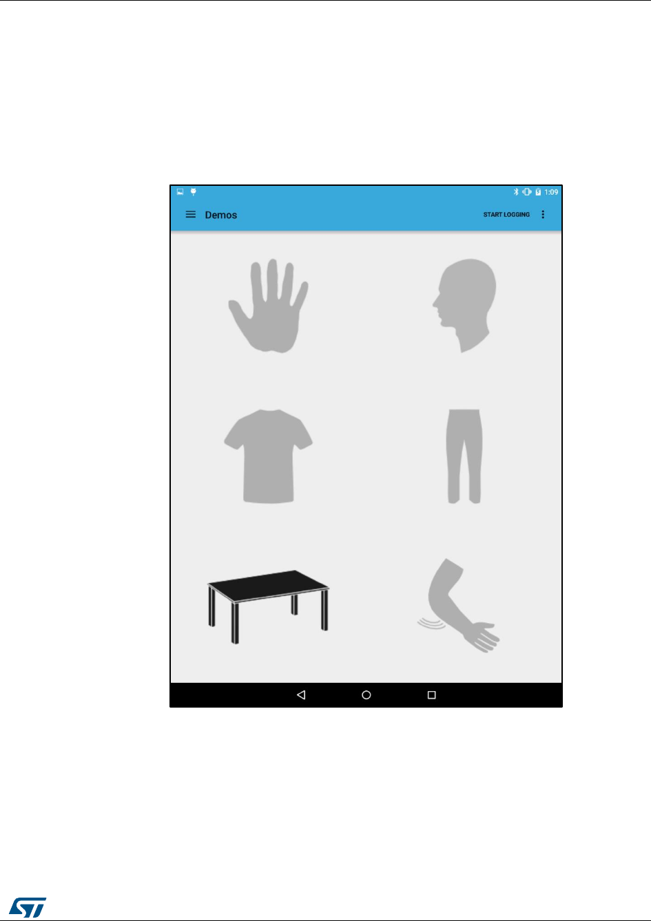
If the osxMotionCP algorithm is enabled, the page shown below is available, with
information about how the user is carrying the board, which equates to phone carry
positions:
on desk
in hand
near head
shirt pocket
trousers pocket
arm swing
Figure 17: BlueMS (Android version) osxMotionCP carry position recognition page
BLUEMICROSYSTEM2 software description
STEVAL-STLKT01V1
24/37
DocID029208 Rev 2
If the osxMotionGR algorithm is the page shown below is available, with gesture
recognition information like:
pick up
glance
wake up in hand
Figure 18: BlueMS (Android version) osxMotionGR gesture recognition page
STEVAL-STLKT01V1
BLUEMICROSYSTEM2 software description
DocID029208 Rev 2
25/37
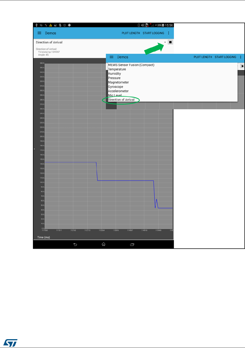
If the osxAcousticSL algorithm is enabled, the page shown below is available, with audio
sound source localization.
Figure 19: BlueMS (Android version) example of audio source localization plot value
System setup guide
STEVAL-STLKT01V1
26/37
DocID029208 Rev 2
2 System setup guide
2.1 Hardware description
This section describes the hardware components needed for developing a sensors based
application.
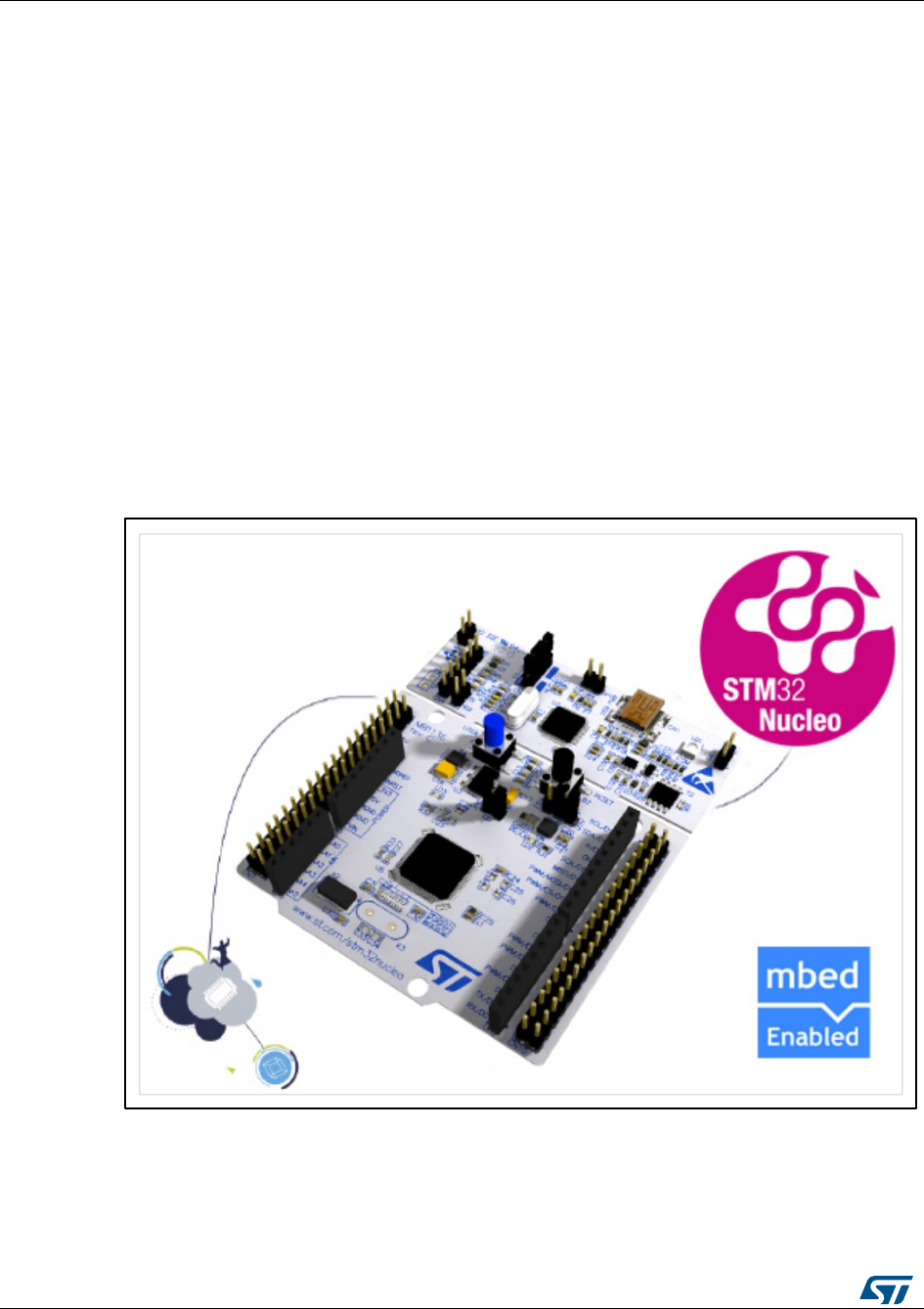
2.1.1 STM32 Nucleo platform
The STM32 Nucleo boards provide an affordable and flexible way for users to try out new
ideas and build prototypes with any STM32 microcontroller lines. The Arduino™
connectivity support and ST morpho headers make it easy to expand the functionality of
the STM32 Nucleo open development platform with a wide range of specialized expansion
boards to choose from. The STM32 Nucleo board does not require any separate probe as
it integrates the ST-LINK/V2-1 debugger/programmer. The STM32 Nucleo board comes
with the comprehensive STM32 software HAL library together with various packaged
software examples.
Information regarding the STM32 Nucleo board is available on www.st.com at
http://www.st.com/stm32nucleo
Figure 20: STM32 Nucleo board
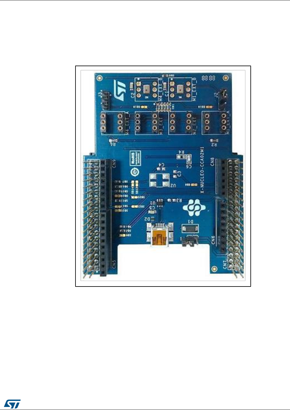
2.1.2 X-NUCLEO-CCA02M1 expansion board
The X-NUCLEO-CCA02M1 is an evaluation board based on digital MEMS microphones. It
is compatible with the morpho connector layout, and is designed around
STMicroelectronics’ MP34DT01-M digital microphones. There are two microphones
STEVAL-STLKT01V1
System setup guide
DocID029208 Rev 2
27/37
soldered onto board and it offers the possibility to plug in additional microphones using
MP32DT01-based coupon evaluation boards (e.g. STEVAL-MKI129V3).
The X-NUCLEO-CCA02M1 allows the acquisition of up to two microphones using the I²S
bus and up to four coupon microphones using I²S and SPI together. In addition, it offers a
USB output for the STM32 Nucleo board. It represents a fast and easy solution for the
development of microphone-based applications as well as a starting point for audio
algorithm implementation.
Figure 21: X-NUCLEO-CCA02M1 board
Information regarding the X-NUCLEO-CCA02M1 expansion board is available on st.com at
http://www.st.com/x-nucleo.
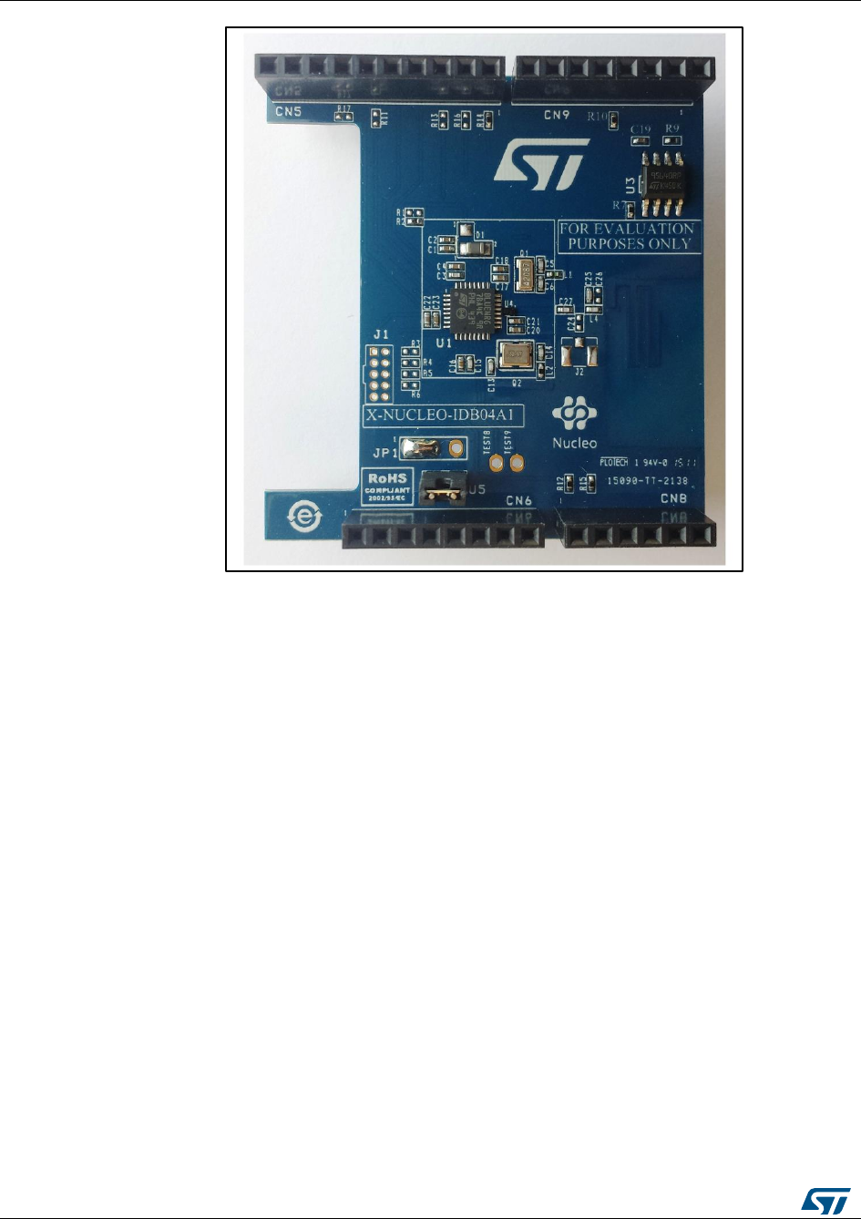
2.1.3 X-NUCLEO-IDB04A1 expansion board
The X-NUCLEO-IDB04A1 is a Bluetooth BlueNRG expansion board usable with the
STM32 Nucleo system. The BlueNRG is a very low power Bluetooth low energy (BLE)
single-mode network processor, compliant with Bluetooth specifications core 4.0.
System setup guide
STEVAL-STLKT01V1
28/37
DocID029208 Rev 2
Figure 22: X-NUCLEO-IDB04A1 expansion board
Information regarding the X-NUCLEO-IDB04A1 expansion board is available on
www.st.com at http://www.st.com/x-nucleo.
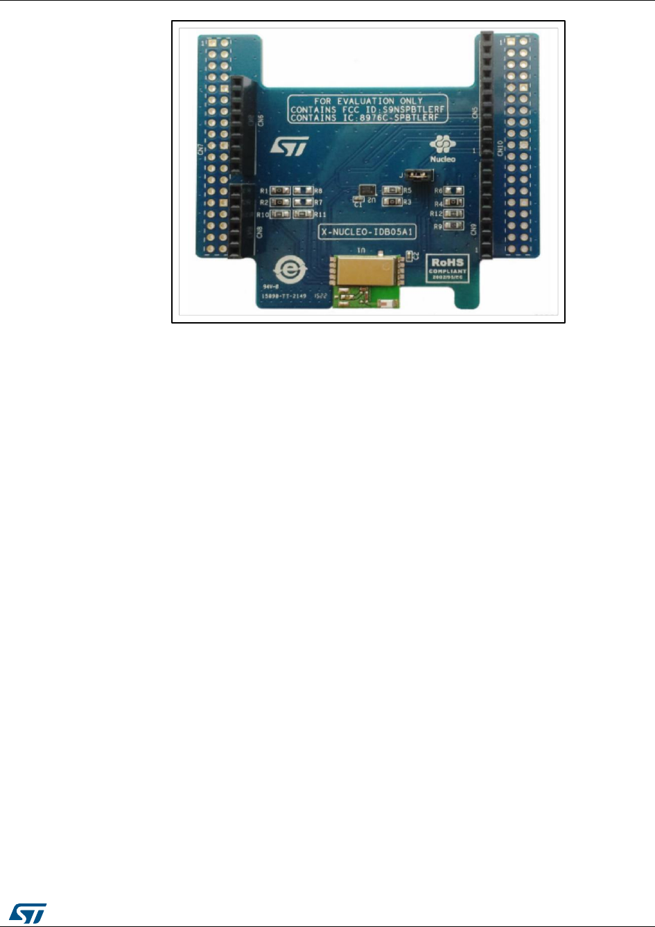
2.1.4 X-NUCLEO-IDB05A1 expansion board
The X-NUCLEO-IDB05A1 is a Bluetooth low energy evaluation board based on the
SPBTLE-RF BlueNRG-MS RF module to allow expansion of the STM32 Nucleo boards.
The SPBTLE-RF module is FCC (FCC ID: S9NSPBTLERF) and IC certified (IC: 8976C-
SPBTLERF). The BlueNRG-MS is a very low power Bluetooth low energy (BLE) single-
mode network processor, compliant with Bluetooth specification v4.2. X-NUCLEO-IDB05A1
is compatible with the ST morpho and Arduino™ UNO R3 connector layout. This expansion
board can be plugged into the Arduino UNO R3 connectors of any STM32 Nucleo board.
STEVAL-STLKT01V1
System setup guide
DocID029208 Rev 2
29/37
Figure 23: X-NUCLEO-IDB05A1 expansion board
Information about the X-NUCLEO-IDB05A1 expansion board is available on www.st.com at
http://www.st.com/x-nucleo
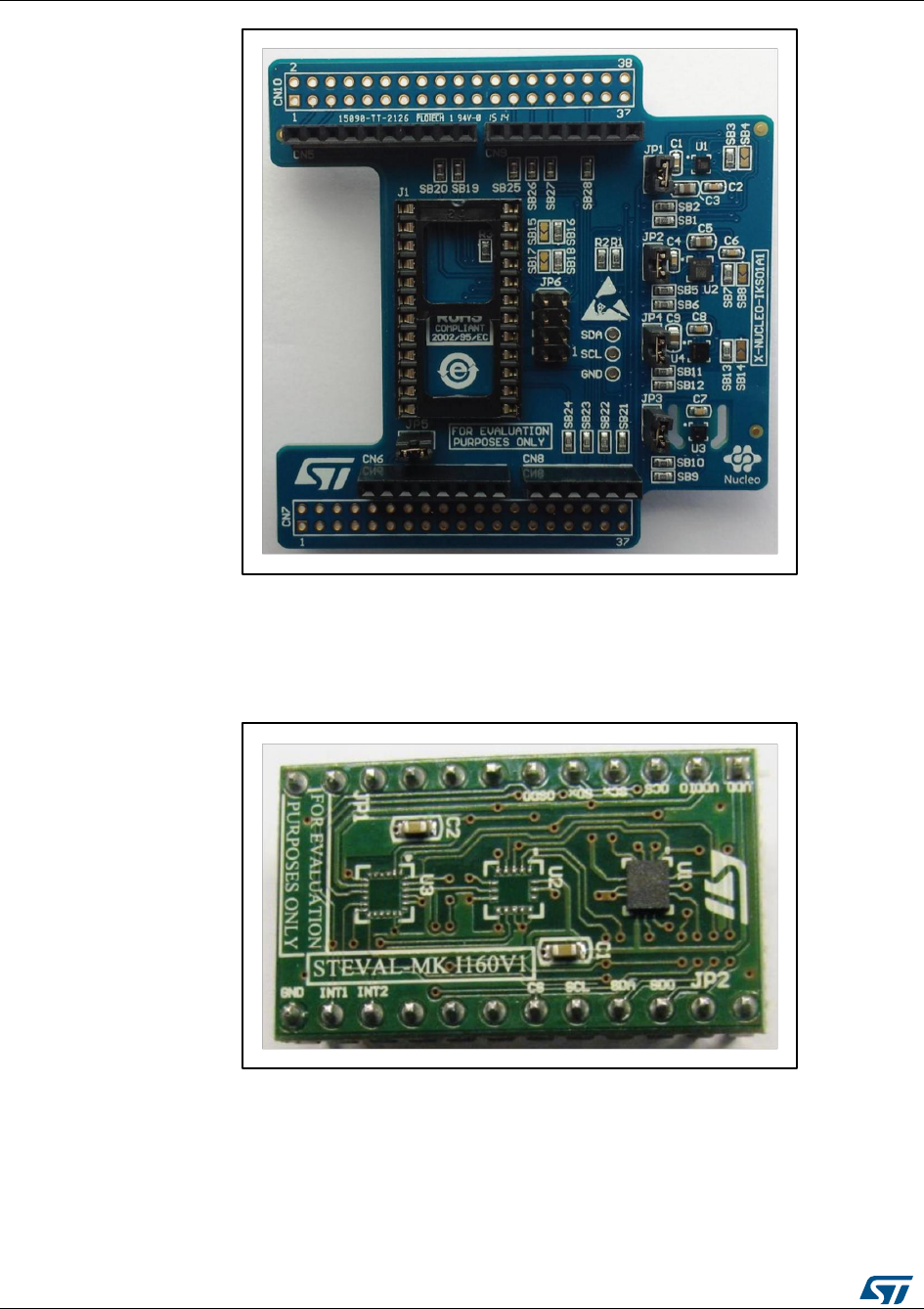
2.1.5 X-NUCLEO-IKS01A1 expansion board
The X-NUCLEO-IKS01A1 figured below is a sensor expansion board for use with the
STM32 Nucleo system. It is also compatible with the Arduino UNO R3 connector layout,
and is designed around the STMicroelectronics humidity (HTS221), pressure (LPS25HB)
and motion sensors (LIS3MDL and LSM6DS0). The X-NUCLEO-IKS01A1 interfaces with
the STM32 MCU via an I²C pin, and the user can change the default I²C address and the
device IRQ by changing one resistor on the evaluation board.
System setup guide
STEVAL-STLKT01V1
30/37
DocID029208 Rev 2
Figure 24: X-NUCLEO-IKS01A1 board
Information about the X-NUCLEO-IKS01A1 expansion board is available on www.st.com
at: http://www.st.com/x-nucleo.
The LSM6DS3 DIL24 adapter board in the figure below can be plugged on top of the X-
NUCLEO-IKS01A1 expansion board.
Figure 25: LSM6DS3 DIL24 adapter board
2.2 Software description
The following software components are needed in order to set up a suitable development
environment for creating applications for the STM32 Nucleo equipped with the sensors,
microphones and Bluetooth low energy expansion boards:

STEVAL-STLKT01V1
System setup guide
DocID029208 Rev 2
31/37
BLUEMICROSYSTEM2: Bluetooth low energy and sensors software for STM32Cube.
BLUEMICROSYSTEM2 firmware and related documentation is available on
www.st.com.
Development tool-chain and Compiler. The STM32Cube expansion software supports
the three following environments:
IAR Embedded Workbench for ARM® (EWARM) toolchain + ST-LINK
RealView Microcontroller Development Kit (MDK-ARM) toolchain + ST-LINK
System Workbench for STM32 + ST-LINK
2.3 Hardware and software setup
This section describes the hardware and software setup procedures. It also describes the
system setup needed for the above.
2.3.1 Hardware setup
The following hardware components are needed:
One STM32 Nucleo development platform (order code: NUCLEO-F401RE or NUCLEO-
L476RG)
One microphone expansion board (order code: X-NUCLEO-CCA02M1)
One sensor expansion board (order code: X-NUCLEO-IKS01A1)
One BlueNRG Bluetooth low energy expansion board (order code: X-NUCLEO-IDB04A1 or
X-NUCLEO-IDB05A1)
One USB type A to Mini-B USB cable to connect the STM32 Nucleo to the PC
2.3.2 Software setup
This section lists the minimum requirements necessary to set up the SDK, run the sample
testing scenario based on the GUI utility and customize applications.
2.3.2.1 Development tool-chains and compilers
Select one of the Integrated Development Environments supported by the STM32Cube
expansion software and follow the system requirements and setup information provided by
the selected IDE provider.
2.3.3 System setup guide
This section describes how to setup different hardware parts before writing and executing
an application on the STM32 Nucleo board with the expansion boards.
2.3.3.1 STM32 Nucleo and expansion boards setup
The STM32 Nucleo board integrates the ST-LINK/V2-1 debugger/programmer. The
developer can download the relevant version of the ST-LINK/V2-1 USB driver by searching
STSW-LINK008 or STSW-LINK009 on www.st.com.
The X-NUCLEO-CCA02M1 sensor board is easily connected to the STM32 Nucleo board
through the morpho connector, as shown below.
System setup guide
STEVAL-STLKT01V1
32/37
DocID029208 Rev 2
Figure 26: STM32 Nucleo plus X-NUCLEO-CCA02M1 boards
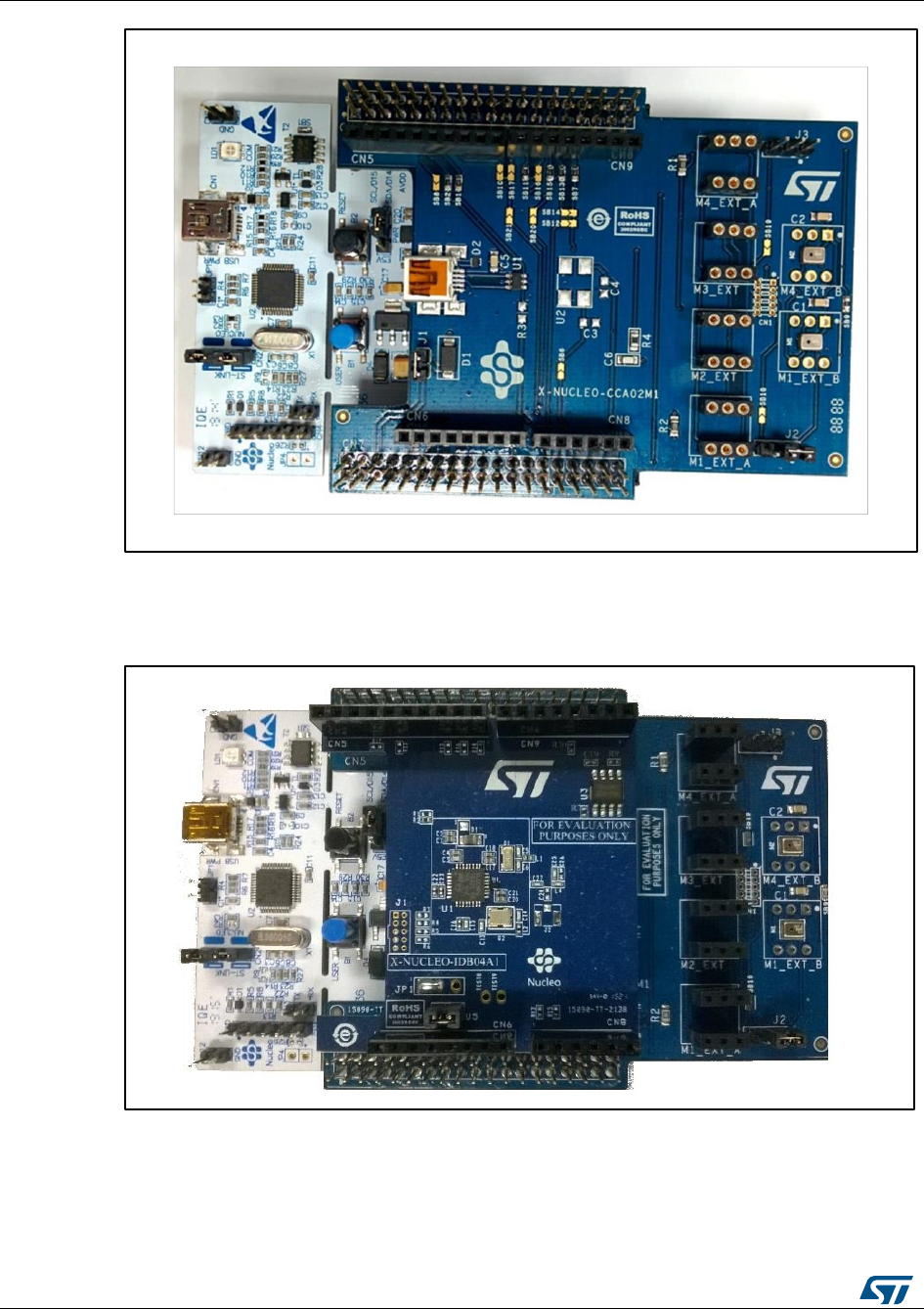
The X-NUCLEO-IDB04A1 or X-NUCLEO-IDB05A1 BlueNRG BLE expansion board is
easily connected to the X-NUCLEO-CCA02M1 board through the Arduino UNO R3
extension connector, as shown below.
Figure 27: STM32 Nucleo plus X-NUCLEO-CCA02M1 plus X-NUCLEO-IDB04A1 boards
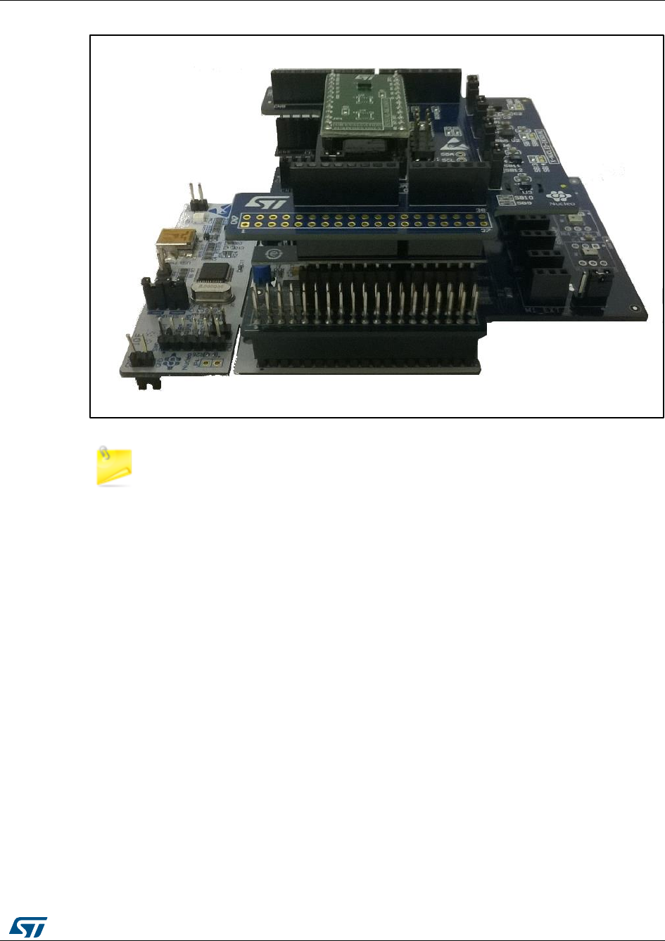
Finally, the X-NUCLEO-IKS01A1 sensors board is easily connected to the X-NUCLEO-
IDB04A1 or X-NUCLEO-IDB05A1 expansion board through the Arduino UNO R3 extension
connector, as shown below.
STEVAL-STLKT01V1 System setup guide
DocID029208 Rev 2
33/37
Figure 28: STM32 Nucleo plus X-NUCLEO-CCA02M1 plus X-NUCLEO-IDB04A1 plus X-
NUCLEO-IKS01A1 plus LSM6DS3 DIL24 boards
The stacking sequence shown above is necessary to optimize the performance of
the SPBTLE-RF module on the X-NUCLEO-IDB05A1 expansion board, and to
reduce interference from its antenna
System setup guide
STEVAL-STLKT01V1
34/37
DocID029208 Rev 2
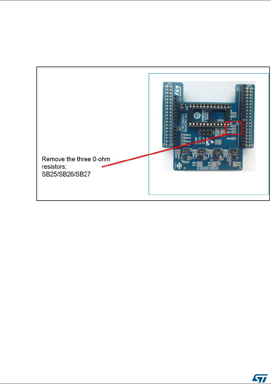
2.3.3.2 Important additional hardware information
For either STM32 Nucleo board: before connecting the X-NUCLEO-IKS01A1 board to the
X-NUCLEO-IDB04A1 or X-NUCLEO-IDB05A1 expansion board through the Arduino UNO
R3 extension connector, remove these 0-ohm resistors:
SB25
SB26
SB27
Figure 29: Resistors to remove from X-NUCLEO-IKS01A1 board
STEVAL-STLKT01V1 System setup guide
DocID029208 Rev 2
35/37
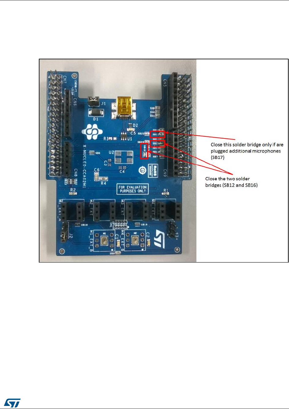
For the NUCLEO-L476RG board only: before connecting the X-NUCLEO-CCA02M1
board to the STM32 Nucleo board morpho connectors, close these solder bridges:
SB12
SB16
SB17 (if additional microphones are connected)
Figure 30: Solder bridges to close on X-NUCLEO-CCA02M1 board (when using NUCLEO-
L476RG board)

Revision history
STEVAL-STLKT01V1
36/37
DocID029208 Rev 2
3 Revision history
Table 1: Document revision history
Date
Version
Changes
12-Apr-2016
1
Initial release.
06-May-2016
2
Minor text edits.

STEVAL-STLKT01V1
DocID029208 Rev 2
37/37
IMPORTANT NOTICE – PLEASE READ CAREFULLY
STMicroelectronics NV and its subsidiaries (“ST”) reserve the right to make changes, corrections, enhancements, modifications, and
improvements to ST products and/or to this document at any time without notice. Purchasers should obtain the latest relevant information on ST
products before placing orders. ST products are sold pursuant to ST’s terms and conditions of sale in place at the time of order
acknowledgement.
Purchasers are solely responsible for the choice, selection, and use of ST products and ST assumes no liability for application assistance or the
design of Purchasers’ products.
No license, express or implied, to any intellectual property right is granted by ST herein.
Resale of ST products with provisions different from the information set forth herein shall void any warranty granted by ST for such product.
ST and the ST logo are trademarks of ST. All other product or service names are the property of their respective owners.
Information in this document supersedes and replaces information previously supplied in any prior versions of this document.
© 2016 STMicroelectronics – All rights reserved

FCC ID:S9NSTILE01
This device complies with part 15 of the FCC Rules.
Operation is subject to the following two conditions:
(1) This device may not cause harmful interference, and
(2) this device must accept any interference received, including interference that may cause
undesired operation.
Notice:
Any changes or modifications not expressly approved by the party responsible for
compliance could void your authority to operate the equipment.
NOTE: This equipment has been tested and found to comply with the limits for a
Class
B digital device, pursuant to part 15 of the FCC Rules. These limits are designed
to
provide reasonable protection against harmful interference in a residential
installation.
This equipment generates, uses and can radiate radio frequency energy and, if not
installed and used in accordance with the instructions, may cause harmful
interference to radio communications. However, there is no guarantee that
interference will not occur in a particular installation. If this equipment does cause
harmful interference to radio or television reception, which can be determined by
turning the equipment off and on, the user is encouraged to try to correct the
interference by one or more of the following measures:
- Reorient or relocate the receiving antenna.
- Increase the separation between the equipment and receiver.
- Connect the equipment into an outlet on a circuit different from that to which the
receiver is connected.
- Consult the dealer or an experienced radio/ TV technician for help.
Modular information form OEM Information to Be Supplied to the End User
by the OEM or Integrator.
The following regulatory and safety notices must be published in
documentation supplied to the end user of the product or system
incorporating an adapter in compliance with local regulations.
Host system must be labeled with " Contains transmitter module
FCC ID: S9NSTILE01 ", FCC ID displayed on label.

IC: 8976C-STILE01
This device complies with Industry Canada licence-exempt RSS
standard(s).
Operation is subject to the following two conditions:
(1) this device may not cause interference, and
(2) this device must accept any interference, including interference
that may cause undesired operation of the device.
This Class B digital apparatus complies with Canadian ICES-0003.
Le présent appareil est conforme aux CNR d'Industrie Canada
applicables aux appareils radio exempts de licence.
L'exploitation est autorisée aux deux conditions suivantes :
(1) l'appareil ne doit pas produire de brouillage, et
(2) l'utilisateur de l'appareil doit accepter tout brouillage
radioélectrique subi, même si le brouillage est susceptible d'en
compromettre le fonctionnement.
by the OEM or Integrator.
The following regulatory and safety notices must be published in
documentation supplied to the end user of the product or system
incorporating an adapter in compliance with local regulations.
Host system must be labeled with " Contains transmitter module
IC: 8976C-STILE01", IC ID displayed on label.