ST Microelectronics S R L WESU1 Evaluation Board User Manual ST Platform name
ST Microelectronics S.R.L. Evaluation Board ST Platform name
User Manual
UMxxxx
USER MANUAL
Evaluation Board
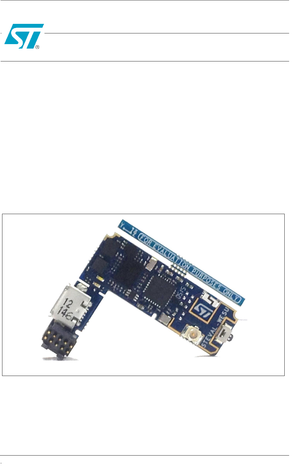
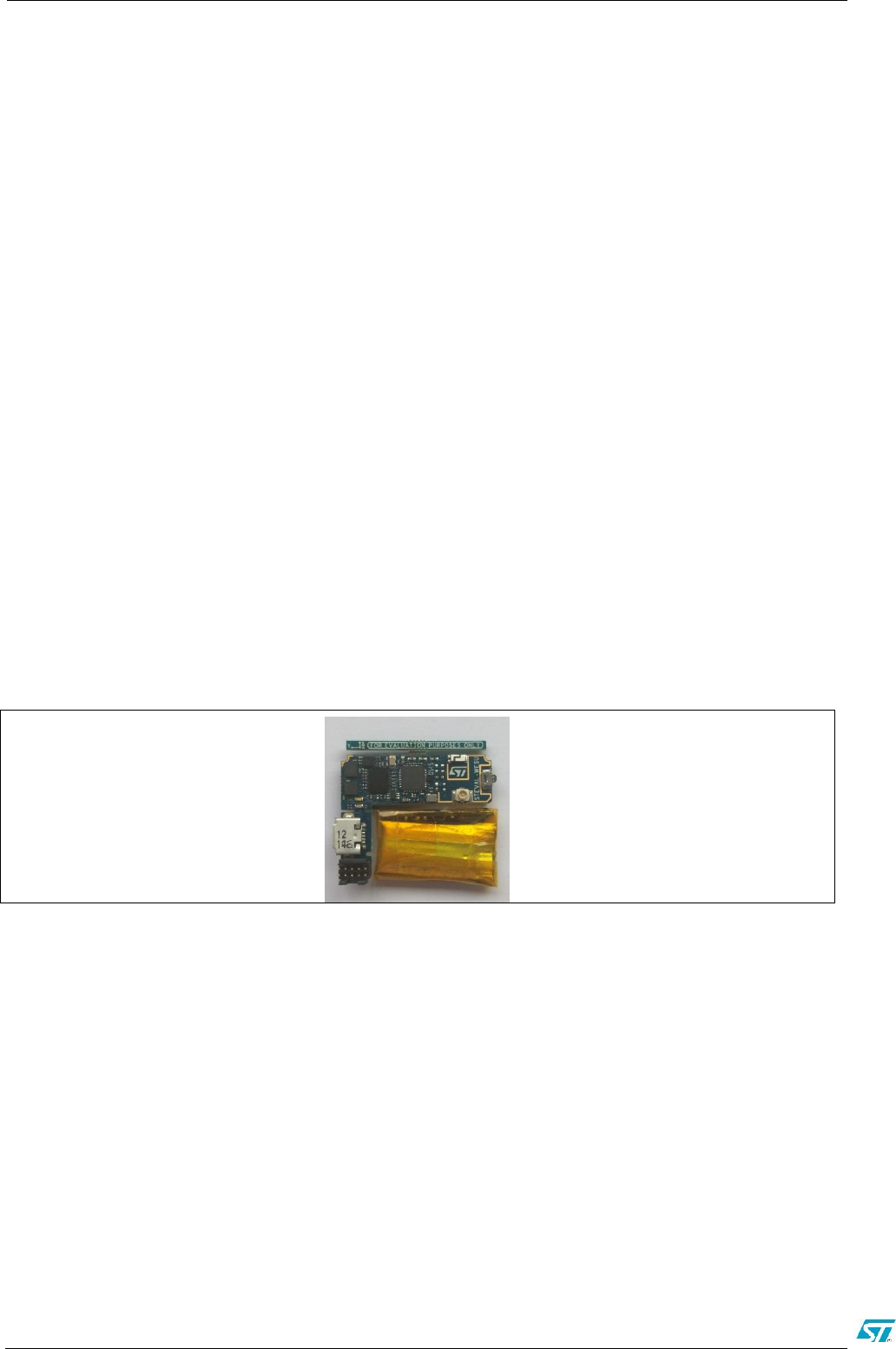
STEVAL-WESU1
July 2015 Rev 0.1 STMicroelectronics Confidential 1/22
Introduction
The STEVAL-WESU1 is a System Evaluation Board designed to provide a cost effective solution
for precise motion sensing in wearable applications. The system is featuring a low power ARM
Cortex-M3 microcontroller unit (STM32L151), an iNEMO inertial module (LSM6DS3), a high
performance magnetometer (LIS3MDL), a barometric pressure sensor (LPS25HB), a Bluetooth®
low energy wireless network processor (BLUENRG-MS) and power management circuitry that
allows fast charging and precise energy estimation (STNS01 and STC3115). The connectivity
granted by the best in class BLUENRG-MS and supported by the integrated balun (BALF-NRG-
01D3) permit to maximize the RF performances with low area occupancy and design effort and
pass the RF Test for FCC certification (FCC ID: S9NWESU1) and IC certification (IC ID: 8976C-
WESU1).
An Android and iOS APP, available on Google Play and Apple Store, can be used for displaying
information sent by the STEVAL-WESU1 through BLE connectivity as well as for setting operative
modes.
Figure 1. STEVAL-WESU1 evaluation board

2/22 Version 0.1 STMicroelectronics Confidential
Table of Contents
1 Board Description and Getting started ................................................................................... 4
1.1 Getting started ........................................................................................................................ 5
2 Hardware description ............................................................................................................... 8
2.1 Microcontroller ........................................................................................................................ 8
2.2 Sensors .................................................................................................................................. 8
2.2.1 LSM6DS3 ............................................................................................................................... 8
2.2.2 LISM3DL ................................................................................................................................ 8
2.2.3 LPS25HB ................................................................................................................................ 9
2.3 BLUENRG-MS and BALF-NRG-01D3 ................................................................................... 9
2.4 Power management ............................................................................................................... 9
2.4.1 STNS01 and STLQ015 .......................................................................................................... 9
2.4.2 STC3115 .............................................................................................................................. 10
2.5 Connectors ........................................................................................................................... 10
2.5.1 Battery connector ................................................................................................................. 10
2.5.2 SWD Connector and external peripherals............................................................................ 11
2.5.3 USB Connector .................................................................................................................... 12
2.5.4 Exposed pad connector ....................................................................................................... 12
2.5.5 uFL connector ...................................................................................................................... 12
2.6 Buttons and LEDs ................................................................................................................ 12
3 Formal notices required by the U.S. Federal Communications Commission ("FCC") ....... 13
4 Formal notices required by the Industry Canada ("IC") ....................................................... 14
5 Board schematic and bill of material ..................................................................................... 15
5.1 Bill of material ....................................................................................................................... 15
5.2 Schematic ............................................................................................................................. 19
6 Revision history ...................................................................................................................... 20
Error! No text of specified style in document. ST application note template
STMicroelectronics Confidential Rev 0.1 4/22
DRAFT
1 Board Description and Getting started
The STEVAL-WESU1 is a System Evaluation Board designed and optimized in order to be a
reference design for users would made their own wearable electronic devices. In fact, the system
architecture is made up of hardware, firmware and software solutions to accelerate the overall
development of all applications: from embedded end-customer devices to mobile software
development. The design choices have been taken to address accurate motion tracking suitable
for training in every kind of activity or sport.
Main Components:
- STM32L151VEY6, ultra-low-power ARM Cortex-M3 MCU with 512 Kbytes FLASH, 48kBytes of
RAM in WLCSP100 package
- BLUENRG-MS, Bluetooth Low Energy (BLE) single-mode network processor, compliant with
Bluetooth specification core 4.0
- BALF-NRG-01D3, 50 Ω balun for BLUENRG-MS transceiver with integrated harmonic filter
- LSM6DS3, iNEMO inertial module 3D accelerometer (±2/4/8g) + 3D gyroscope
(±245/500/2000dps)
- LIS3MDL, MEMS 3D magnetometer (±4/8/12/16 gauss)
- LPS25HB, MEMS pressure sensor, 260-1260 hPa absolute digital output barometer
- STC3115, Gas gauge IC with alarm output
- STNS01, Li-Ion linear battery charger
- STLQ015XG30R, linear voltage regulator
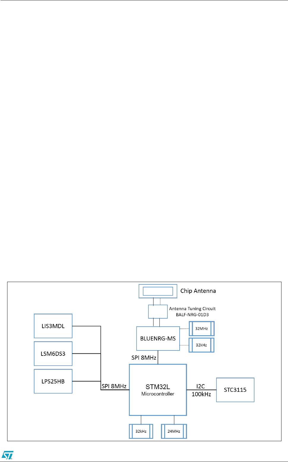
The Figure 2 shows a function block diagram of the board where the sensors and the BLUENRG-
MS are connected to microcontroller through two separate SPI peripherals, meanwhile the power
management is driven by I2C peripheral. The system can be powered with USB connected to PC
or through specific battery. The USB is also used for battery recharge. Figure 3 shows the block
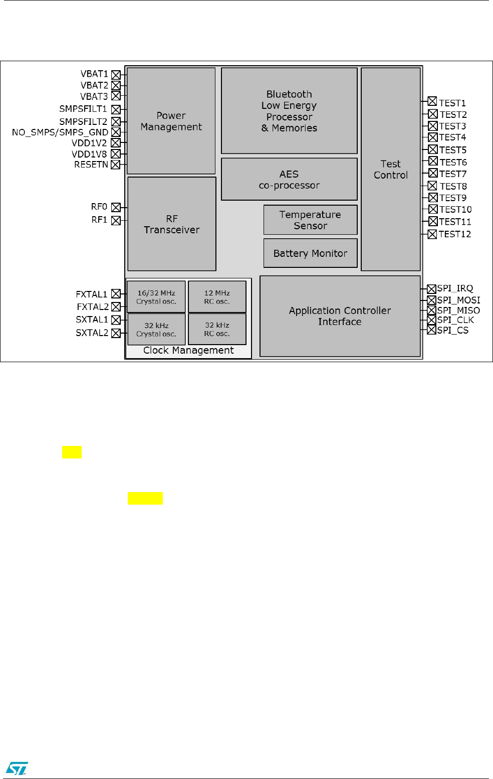
diagram of the RFIC BLUENRG-MS.
Figure 2. Functional Block Diagram
ST application note template Error! No text of specified style in document.
STMicroelectronics Confidential Rev 0.1 5/22
DRAFT
Figure 3. Block Diagram of RFIC: BlueNRG-MS
1.1 Getting started
The system is delivered fully assembled and connected with battery and with LDO off (shipment
mode, with 2uA power consumption).
It can be simply switched ON with USB-powered cable insertion (micro B male plug). The USB
port connector can be used for battery charging.
The system takes up to 160mA (@5V) to recharge the battery; for this reason you can use both
USB wall adapter and PC port with this capability. Two LEDs (LED1 and LED2, see Figure 3)
describes the Application Status and the Battery Charging Status.
The Charging LED (LED 2) could be:
- Light ON, the USB plug is correctly connected and the board is charging;
- Light OFF, the board is not charging (use USB cable reconnection to force re-start);
- Blinking (approximately at 1Hz), charging failure (e.g. over-temperature, three wires battery not
connected);
It is important to avoid deep discharge (< 30%) to maintain battery integrity and to prevent long-
term malfunctioning.
The User Button (see Figure 4) can be pressed to enter and exit the Stop MODE.
At power on the Application LED (LED1) starts with one smooth blink and in normal operation it
blinks at 2s interval; after BLUENRG-MS connection the blinking interval becomes 1s and
STEVAL-WESU1 system reads sensors data and sends it to a Bluetooth Smart Ready device; the
data is displayed using a dedicated App.
Error! No text of specified style in document. ST application note template
6/22 Version 0.1 STMicroelectronics Confidential
DRAFT
A custom (1.27 mm pitch) SWD connector is used to have a compact solution, since to program
the on-board STM32L151 it has been included in the package a specific adapter useful to be
connected to a programmer tool (e.g. ST-LINK/v2).
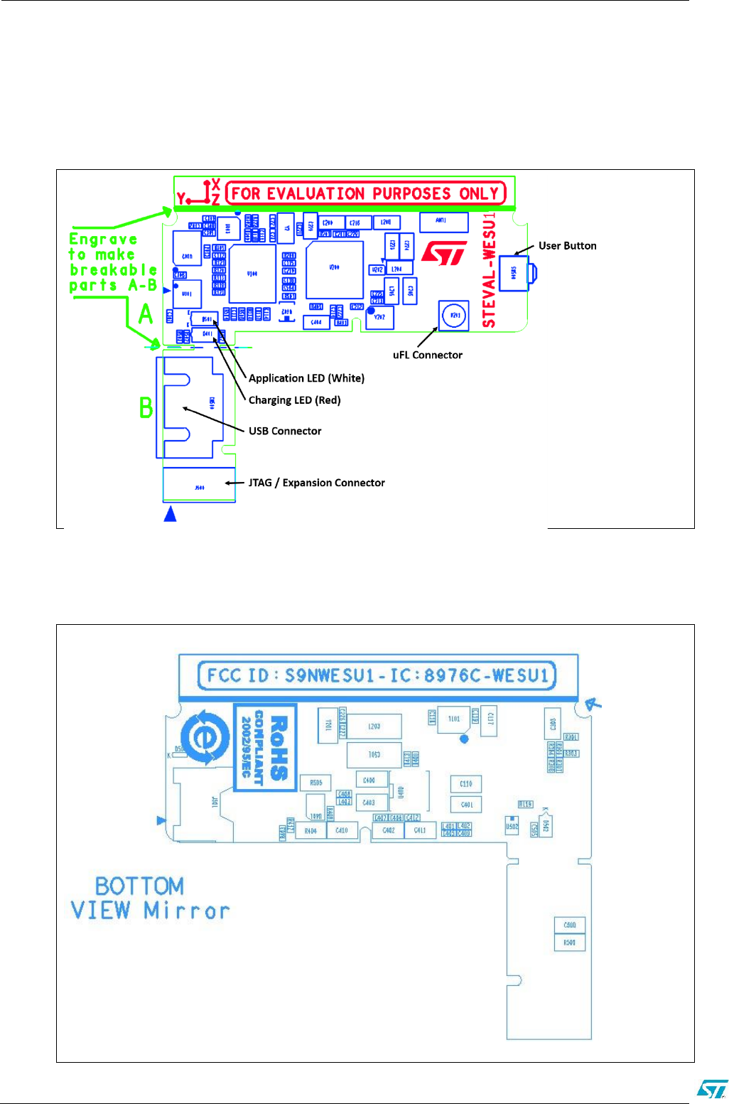
Figure 4. Board Layout – top layer
Figure 5. Board Layout – Bottom layer

ST application note template Error! No text of specified style in document.
STMicroelectronics Confidential Rev 0.1 7/22
DRAFT
Once it has been verified the battery is enough charged, the board is ready to be used. To
visualize the information sent through the Bluetooth Low Energy connectivity is
fundamental to install one of the App available for the Smartphone and Tablet:
- ST WESU Android App, available on Google Play;
- ST WESU iOS App available on Apple Store.
To use this App is need a Smartphone or Tablet supporting the BLE connectivity, i.e.
iPhone 4S and subsequent or, an Android based device with Android OS 4.3 or higher.

Error! No text of specified style in document. ST application note template
8/22 Version 0.1 STMicroelectronics Confidential
DRAFT
2 Hardware description
This section describes the main components present on the board and described in
Figure 3 and 4.
2.1 Microcontroller
STM32L151VEY6 is an ultra-low-power microcontroller unit based on ARM Cortex M3. It
features a great range of low power modes and an efficient voltage scaling that allows
power saving.
2.2 Sensors
Thanks to their overall integration level the embedded sensors offer great flexibility in terms
of accuracy of the system and in terms of power consumption.
The integrated sensors perfectly fit the needs of an accurate AHRS algorithm (e.g.
embedded iNEMO-Engine running on the STM32L151VEY6), height estimation and
everything needed for wearable motion tracking: from extreme low power activity tracker to
more advanced motion reconstruction.
2.2.1 LSM6DS3
The LSM6DS3 is a system-in-package featuring a 3D digital accelerometer and a 3D digital
gyroscope performing at 1.25 mA (up to 1.6 kHz ODR) in high performance mode and
enabling always-on low-power features for an optimal motion experience for the consumer.
Up to 8 Kbyte of FIFO with dynamic allocation of significant data (i.e. external sensors, time
stamp, etc) allows the overall power saving of the system.. ST’s family of MEMS sensor
modules leverages the robust and mature manufacturing processes already used for the
production of micro machined accelerometers and gyroscopes. The various sensing
elements are manufactured using specialized micromachining processes, while the IC
interfaces are developed using CMOS technology that allows the design of a dedicated
circuit which is trimmed to better match the characteristics of the sensing element. The
LSM6DS3 has a full-scale acceleration range of ±2/±4/±8/±16 g and an angular rate range
of ±125/±245/±500/±1000/±2000 dps. High robustness to mechanical shock makes the
LSM6DS3 the preferred choice of system designers for the creation and manufacturing of
reliable products. The LSM6DS3 is available in a plastic land grid array (LGA) package.
2.2.2 LISM3DL
The LIS3MDL is an ultra-low-power high performance three-axis magnetic sensor. The
LIS3MDL has user-selectable full scales of ±4/ ±8/ ±12/±16 gauss. The self-test capability
allows the user to check the functioning of the sensor in the final application. The device
may be configured to generate interrupt signals for magnetic field detection. The LIS3MDL
includes an I2C serial bus interface that supports standard and fast mode (100 kHz and
400 kHz) and SPI serial standard interface. The LIS3MDL is available in a small thin plastic
land grid array package (LGA) and is guaranteed to operate over an extended temperature
range of -40 °C to +85 °C.

ST application note template Error! No text of specified style in document.
STMicroelectronics Confidential Rev 0.1 9/22
DRAFT
2.2.3 LPS25HB
The LPS25HB is an ultra-compact absolute piezo-resistive pressure sensor. It includes a
monolithic sensing element and an IC interface able to take the information from the
sensing element and to provide a digital signal to the external world.
Thanks to its great accuracy (1 Pa RMS, 24bit ADC resolution), its bandwidth (1 Hz – 25
Hz) and to its very low power consumption (4uA low power mode, 25uA high performance
mode) the integration of this sensor is suitable for height estimation (e.g. VRU Vertical
Reference Unit) and to enhance standard IMU performances with high frequency altitude
reference.
2.3 BLUENRG-MS and BALF-NRG-01D3
The BLUENRG-MS is a very low power Bluetooth low energy (BLE) single-mode network
processor, compliant with Bluetooth specification v4.1. The BLUENRG-MS can act as
master or slave. The entire Bluetooth low energy stack runs on the embedded Cortex M0
core. The non-volatile Flash memory allows on-field stack upgrading. The BLUENRG-MS
allows applications to meet the tight advisable peak current requirements imposed with the
use of standard coin cell batteries. The maximum peak current is only 8.2 mA at 0 dBm of
output power. Ultra low-power sleep modes and very short transition times between
operating modes allow very low average current consumption, resulting in longer battery
life. The BLUENRG-MS offers the option of interfacing with external microcontrollers using
SPI transport layer.
BALF-NRG-01D3 is a 50Ω conjugate match to BLUENRG-MS (QFN32 package) that
integrates balun transformer and harmonics filtering. It features high RF performances with
a very small footprint and a RF BOM reduction. It has been chosen as the best trade-off for
costs, area occupation and high radio performances. The layout has been optimized to
match 4 layers design and a chip antenna.
2.4 Power management
The power management block includes the STNS01, the STLQ015 and the STC3115
2.4.1 STNS01 and STLQ015
The STNS01 is a linear charger for single-cell Li-Ion batteries.
In STEVAL-WESU1 system it is configured as battery charger and as power path selected
between USB power source and battery power source.
The STNS01's battery charger is designed to charge single cell Li-Ion batteries up to 4.2 V
using a CC-CV charging algorithm (see STNS01 datasheet for more details). When a valid
input voltage is detected, the STNS01 starts the charge cycle and the CHG pin switches
from high impedance to low level. The CHG pin is connected to LED2 to monitor the
charger.
The charging status LED (LED 2) can be:
- solid ON: the USB plug is correctly connected and the board is charging;
- solid OFF: the board is not charging (use USB cable reconnection to force re-start);
- blinking (approx. 1Hz): charging failure (e.g. over-temperature, three wires battery not
connected);
Error! No text of specified style in document. ST application note template
10/22 Version 0.1 STMicroelectronics Confidential
DRAFT
The SYS pin is the voltage output of STNS01 selected power path. That SYS pin is
connected to the linear voltage regulator STLQ015XG30R that provide a 3V (VDD) to all
other devices.
The STM32L151 is also connected to its SHDN pin to disconnect the power delivery to
most of the devices and enable the shipment mode.
2.4.2 STC3115
The STC3115 includes the hardware functions required to implement a low-cost gas gauge
for battery monitoring. The STC3115 uses current sensing, Coulomb counting and accurate
measurements of the battery voltage to estimate the state-of-charge (SOC) of the battery.
An internal temperature sensor simplifies implementation of temperature compensation.
An alarm output signals a low SOC condition and can also indicate low battery voltage. The
alarm threshold levels are programmable.
The STC3115 offers advanced features to ensure high performance gas gauging in all
application conditions.
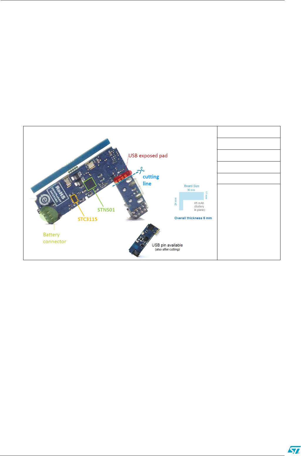
2.5 Connectors
The following sub-sections describe the connectors of STEVAL-WESU1 board (see
Figure 4 as reference). The STEVAL-WESU1 has “L” form factor (see Figure 4), suitable
to host the battery (i.e. 12xd25mm @ 85 mAh) in plane with the PCB and optimize the
final design.
Figure 5 Photo of STEVAL-WESU1 with Battery
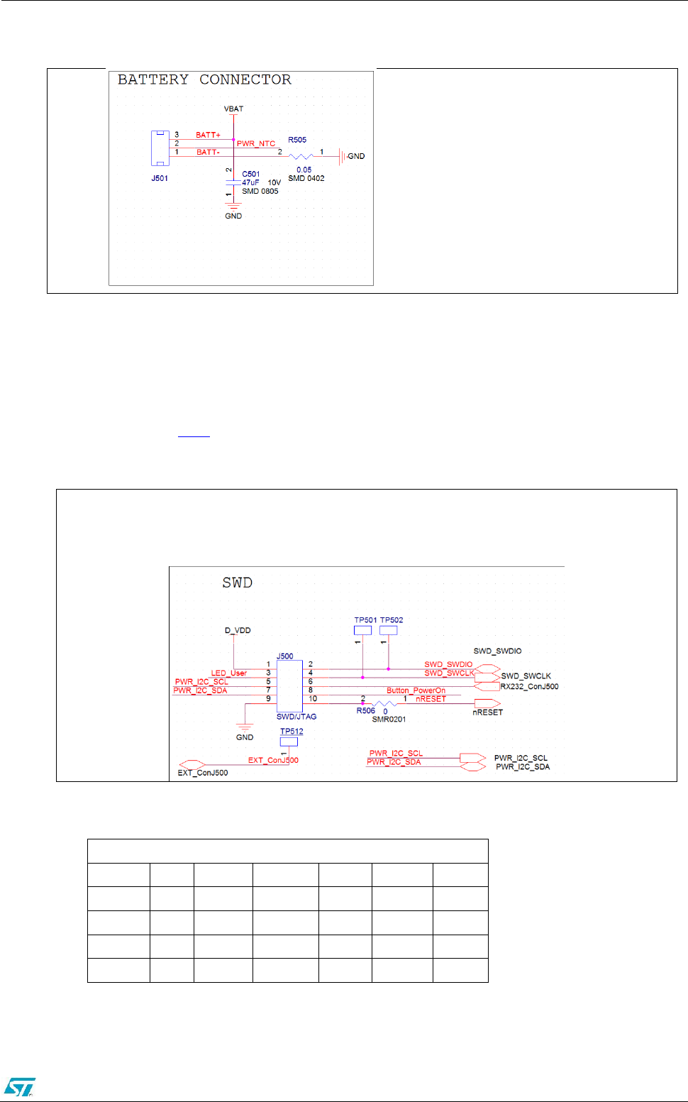
2.5.1 Battery connector
Battery connector is placed on the shrink side of the board (see Figure 2). Its hardware
connection is shown in Figure 6
Figure 6 Battery connector Schematic
ST application note template Error! No text of specified style in document.
STMicroelectronics Confidential Rev 0.1 11/22
DRAFT
2.5.2 SWD Connector and external peripherals
A custom 10 pin (1.27 mm pitch) connector is soldered. It can be used:
- to program on-board microcontroller through a dedicated adapter connected to
programmer tool (like ST-Link) (Figure 7)
- as an expansion connector to allow user to access to other board features as
described in Table1
Figure 7: SWD Connector
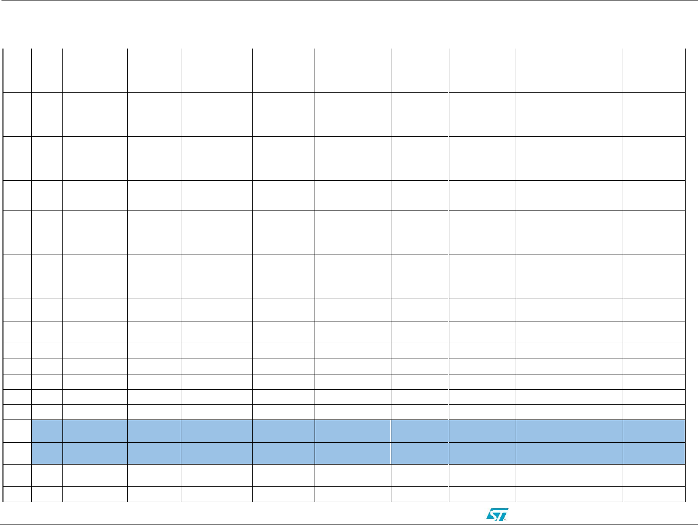
Table1 Expansion Connector GPIO Description
Expansion Connector GPIO Description
Exp. Pin J500
Port/Pin
Default func.
Expansion PIN
PWM
USART
ADC
8
A2
Push Button
1
TIM2CH3
USART2_TX
ADC_CH2
3
B0
User LED
2
TIM3CH3
ADC_CH8
6
A3
-
3
TIM2CH4
USART2_RX
ADC_CH3
TP512
B12
-
4
TIM10CH1
ADC_CH18
Error! No text of specified style in document. ST application note template
12/22 Version 0.1 STMicroelectronics Confidential
DRAFT
2.5.3 USB Connector
The USB connector accepts a micro USB type B and it is used to charge the battery or to
power the board if battery is not present.
2.5.4 Exposed pad connector
STEVAL-WESU1 gives the possibility to reduce form factor by cutting PCB area hosting
USB connector and expansion connector (see cutting line in 8). USB feature will be
accessible by exposed pads on the bottom of the PCB (8). Firmware upgrade will be
possible only over the air or via USB DFU.
Figure 8: STEVAL-WESU1 Exposed Pads
1: USB DP
2: USB 5V
3: GND
4: USB DM
5: TP512 – Expansion PIN 4 test
point
2.5.5 uFL connector
The uFL connector U201 (not mounted) is connected to BLUENRG-MS RF path through
C206 (not mounted). By soldering a 51pF capacitor and desoldering L204, the uFL
connector RF path can be activated, useful for debug purposes.
2.6 Buttons and LEDs
The STEVAL-WESU1 board has 2 LEDs and only one button for user operations.

ST application note template Error! No text of specified style in document.
STMicroelectronics Confidential Rev 0.1 13/22
DRAFT
3 Formal notices required by the U.S. Federal
Communications Commission ("FCC")
Model: STEVAL-WESU1
FCC ID: S9NWESU1
Any changes or modifications to this equipment not expressly approved by
STMicroelectronics may cause harmful interference and void the user’s authority to
operate this equipment.
This device complies with part 15 of the FCC rules. Operation is subject to the following
two conditions:
1. This device may not cause harmful interference, and
2. This device must accept any interference received, including interference that may
cause undesired operation.
For Class A Digital Devices
This equipment has been tested and found to comply with the limits for a Class A digital
device, pursuant to part 15 of the FCC Rules. These limits are designed to provide
reasonable protection against harmful interference when the equipment is operated in a
commercial environment. This equipment generates, uses, and can radiate radio
frequency energy and, if not installed and used in accordance with the instruction manual,
may cause harmful interference to radio communications. Operation of this equipment in
a residential area is likely to cause harmful interference in which case the user will be
required to correct the interference at his own expense.
For Class B Digital Devices
This equipment has been tested and found to comply with the limits for a Class B digital
device, pursuant to part 15 of the FCC Rules. These limits are designed to provide
reasonable protection against harmful interference in a residential installation. This
equipment generates uses and can radiate radio frequency energy and, if not installed
and used in accordance with the instructions, may cause harmful interference to radio
communications. However, there is no guarantee that interference will not occur in a
particular installation. If this equipment does cause harmful interference to radio or
television reception, which can be determined by turning the equipment off and on, the
user is encouraged to try to correct the interference's by one or more of the following
measures:
Reorient or relocate the receiving antenna.
Increase the separation between the equipment and the receiver.
Connect the equipment into an outlet on a circuit different from that to which the
receiver is connected.
Consult the dealer or an experienced radio/TV technician for help.

Error! No text of specified style in document. ST application note template
14/22 Version 0.1 STMicroelectronics Confidential
DRAFT
4 Formal notices required by the Industry Canada
("IC")
Model: STEVAL-WESU1
IC: 8976C-WESU1
English:
This Class A or B digital apparatus complies with Canadian CS-03.
Changes or modifications not expressly approved by the party responsible for compliance
could void the user’s authority to operate the equipment.
This device complies with Industry Canada licence-exempt RSS standard(s). Operation is
subject to the following two conditions: (1) this device may not cause interference, and (2)
this device must accept any interference, including interference that may cause undesired
operation of the device.
French:
Cet appareil numérique de la classe A ou B est conforme à la norme CS-03 du Canada.
Les changements ou les modifications pas expressément approuvés par la partie
responsable de la conformité ont pu vider l’autorité de l'utilisateur pour actionner
l'équipement.
Le présent appareil est conforme aux CNR d'Industrie Canada applicables aux appareils
radio exempts de licence. 'exploitation est autorisée aux deux conditions suivantes: (1)
l'appareil ne doit pas produire de brouillage, et (2) l'utilisateur de l'appareil doit accepter
tout brouillage radioélectrique subi, même si le brouillage est susceptible d'en
compromettre le fonctionnement.
Error! No text of specified style in document. ST application note template
STMicroelectronics Confidential Rev 0.1 15/22
DRAFT
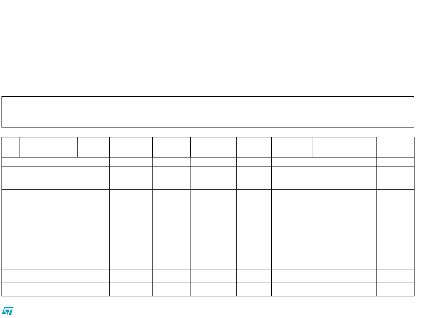
5 Board schematic and bill of material
This section contains the bill of material and layout of the STEVAL-WESU1
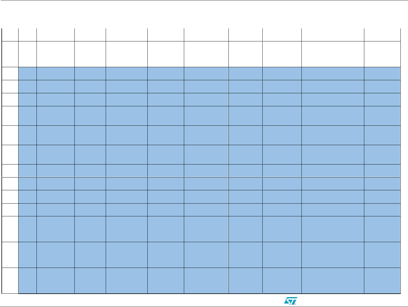
5.1 Bill of material
BOM STEVAL-WESU1
Item
Q.ty
Reference
Part/Value
Voltage
/Ampere
/Ohm
Type /
Additional
Notes
Tolerance
Package
Manufacturer
Manufacturer Code
More Info
1
1
ANT1
2.4 GHz
Chip Antenna
SMD
Pulse
W3008C
2
1
CN500
Micro_USB
_AB
Molex
47590-0001
3
5
C110,C200,C2
16,C401,C411
1uF
6.3V
Ceramic X5R
±10%
SMD 0402
Murata
GRM155R60J105KE19D
4
23
C111,C112,C1
13,C114,C115,
C116,C201,C2
19,C222,C225,
C228,C302,C3
04,C305,C306,
C307,C308,C3
09,C406,C407,
C412,C504,C5
05
100nF
16V
Ceramic X5R
±10%
SMD 0201
Murata
GRM033R61C104KE84D
5
4
C117,C303,C4
00,C404
10uF
6.3V
Ceramic X5R
±20%
SMD 0402
TDK
C1005X5R0J106M050BC
6
2
C118,C119
10pF
25V
Ceramic C0G,
NP0
±0.5pF
SMD 0201
TDK
C0603C0G1E100D030BA
Error! No text of specified style in document. ST application note template
16/22 Version 0.1 STMicroelectronics Confidential
DRAFT
7
1
C206
51pF NOT
MOUNT
50V
Ceramic C0G
±10%
SMD 0402
Murata
GRM1555C1H510GA01D
Mandatory
Use
Manuf.Code
Marked
8
2
C212,C213
12p
50V
CH
±0.1pF
SMD 0201
Murata
GRM0335C1H120GA01
Mandatory
Use
Manuf.Code
Marked
9
2
C214,C221
100p
16V
Ceramic X7R
±10%
SMD 0201
Murata
GRM033R71C101KD01D
Mandatory
Use
Manuf.Code
Marked
10
2
C223,C224
Not Mount
Not Mount
Not Mount
Not Mount
SMD 0402
Murata
Not Mount
11
2
C226,C227,
C22,C23
15p
25V
C0G
±0.1pF
SMD 0201
Murata
GJM0336C1E150FB01D
Mandatory
Use
Manuf.Code
Marked
12
1
C229
150n
6.3V
Ceramic X5R
±10%
SMD 0402
Murata
GRM155R60J154KE01D
Mandatory
Use
Manuf.Code
Marked
13
2
C402,C403
2.2uF
6.3V
Ceramic
X5R(EIA)
±20%
SMD0402
Murata
GRM155R60J225ME95D
14
3
C405,C408,C4
09
10nF
10V
Ceramic X7R
±10%
SMD 0201
Murata
GRM033R71A103KA01D
15
1
C410
220nF
16V
Ceramic X7R
±10%
SMD 0402
Murata
GRM155R71C224KA12D
16
1
C500
4.7nF
50V
Ceramic X7R
±10%
SMD 0402
Murata
GRM155R71H472KA01D
17
1
C501
47uF
10V
Ceramic X5R
±20%
SMD 0805
TDK
C2012X5R1A476M125AC
18
1
D401
RED
LED
VISHAY
VLMS1500-GS08
19
1
D500
WHITE
LED
VISHAY
VLMW1500-GS08
20
1
D501
ESDALC6V1
-1U2
ST0201
ST
ESDALC6V1-1U2
ST-SUPPLY
21
1
D502
ESDA7P60-
1U1M
QFN
ST
ESDA&P60-1U1M
ST-SUPPLY
22
1
J500
SWD/JTAG
THR 1.27
mm 2x5
SAMTEC
FTSH-105-01-F-D-K
23
1
J501
CON3
SMT 3W 1.2
Molex
78171-0003

ST application note template Error! No text of specified style in document.
STMicroelectronics Confidential Rev 0.1 17/22
DRAFT
mm pitch
24
1
L203
10uH
20%
SMD 0805
Murata
LQM21FN100M70L
Mandatory
Use
Manuf.Code
Marked
25
1
L204
0R OHM
±0,1nH
SMD 0402
Murata
TBD
26
1
L205,L206
3.9nH
±0,3nH
SMD 0201
Murata
LQG15HN3N9SO2D
Mandatory
Use
Manuf.Code
Marked
27
3
L401,L402,L40
3
1.5 Ohm
215 mA
SMD 0201
Murata
BLM03BD471SN1D
28
4
R113,R309,R4
05,R506
0
±1%
SMD 0201
ANY
ANY
29
10
R116,R117,R1
19,R120,R121,
R122,R123,R2
00,R201,R501
10k
±1%
SMD 0201
ANY
ANY
30
5
R301,R302,R3
03,R307,R308
0
±1%
SMD 0201
ANY
ANY
31
5
R114,R118,R3
04,R305,R306
0-NOT
MOUNT
±1%
SMD 0201
ANY
ANY
32
1
R400
2K
±1%
SMD 0201
ANY
ANY
33
1
R401
1R
±1%
SMD 0201
ANY
ANY
34
1
R402
60 - 0.05W
±1%
SMD 0201
ANY
ANY
35
2
R403-R408
1K
±1%
SMD 0201
ANY
ANY
36
1
R404
10K NTC -
NOT
MOUNT
±1%
SMD 0402
Vishay
NTCS0402E3103FLT
37
1
R412
1M
±1%
SMD 0201
ANY
ANY
38
1
R413
33K
±1%
SMD 0201
ANY
ANY
39
1
R500
1M
±1%
SMD 0201
ANY
ANY
40
2
R502,R503
100K
±1%
SMD 0201
ANY
ANY
41
1
R504
100
±1%
SMD 0201
ANY
ANY
42
1
R505
0.05
±1%
SMD 0402
WELWYN
LRCS0402-0R05FT5
43
1
SW500
SW
Omron
B3U-3000P
Error! No text of specified style in document. ST application note template
18/22 Version 0.1 STMicroelectronics Confidential
DRAFT
PUSHBUTT
ON-DPST
44
1
U201
U.FL
connector -
NOT
MOUNT
50 Ohm - 6 Ghz
SMD Coaxial
Connector
SMT
Hirose
U.FL-R-SMT-1(10)
45
1
U100
STM32L15
1VEY6
WLCSP104
ST
STM32L151VEY6
ST-SUPPLY
46
1
U200
BLUENRG-
MS
VFQPN32 5x5
mm
ST
BLUENRG-MSQTR
ST-SUPPLY
47
1
U202
BALF-NRG-
01D3
FLIP CHIP 4
ball
ST
BALF-NRG-01D3
ST-SUPPLY
48
1
U301
LPS25HB
HLGA-10L
(2.5 x 2.5x
0.76 mm)
ST
LPS25HB
ST-SUPPLY
49
1
U302
LSM6DS3
LGA-14L
(2.5x3x0.83
mm)
ST
LSM6DS3
ST-SUPPLY
50
1
U303
LIS3MDL
VFLGA-12
(2.0x2.0x1.0
mm)
ST
LIS3MDL
ST-SUPPLY
51
1
U400
STNS01
DFN12L (3x3
mm)
ST
STNS01
ST-SUPPLY
52
1
U401
STC3115
CSP (1.4 x 2.0
mm)
ST
STC3115
ST-SUPPLY
53
1
U402
STLQ015XG
30R
SOT666
ST
STLQ015XG30R
ST-SUPPLY
54
1
U502
USBULC6-
2M6
uQFN
ST
USBULC6-2M6(uQFN)
ST-SUPPLY
55
2
Y2, Y201
NX2012SA
32k
EXS00A-
MU00389
NDK
56
1
Y101
NX2016SA
24MHZ
EXS00A-
CS05544
NDK
57
1
Y202
NX2016SA
32MHz
EXS00A-
CS06644
NDK

ST application note template Error! No text of specified style in document.
STMicroelectronics Confidential Rev 0.1 19/22
DRAFT
5.2 Schematic
Error! No text of specified style in document. ST application note template
20/22 Version 0.1 STMicroelectronics Confidential
DRAFT
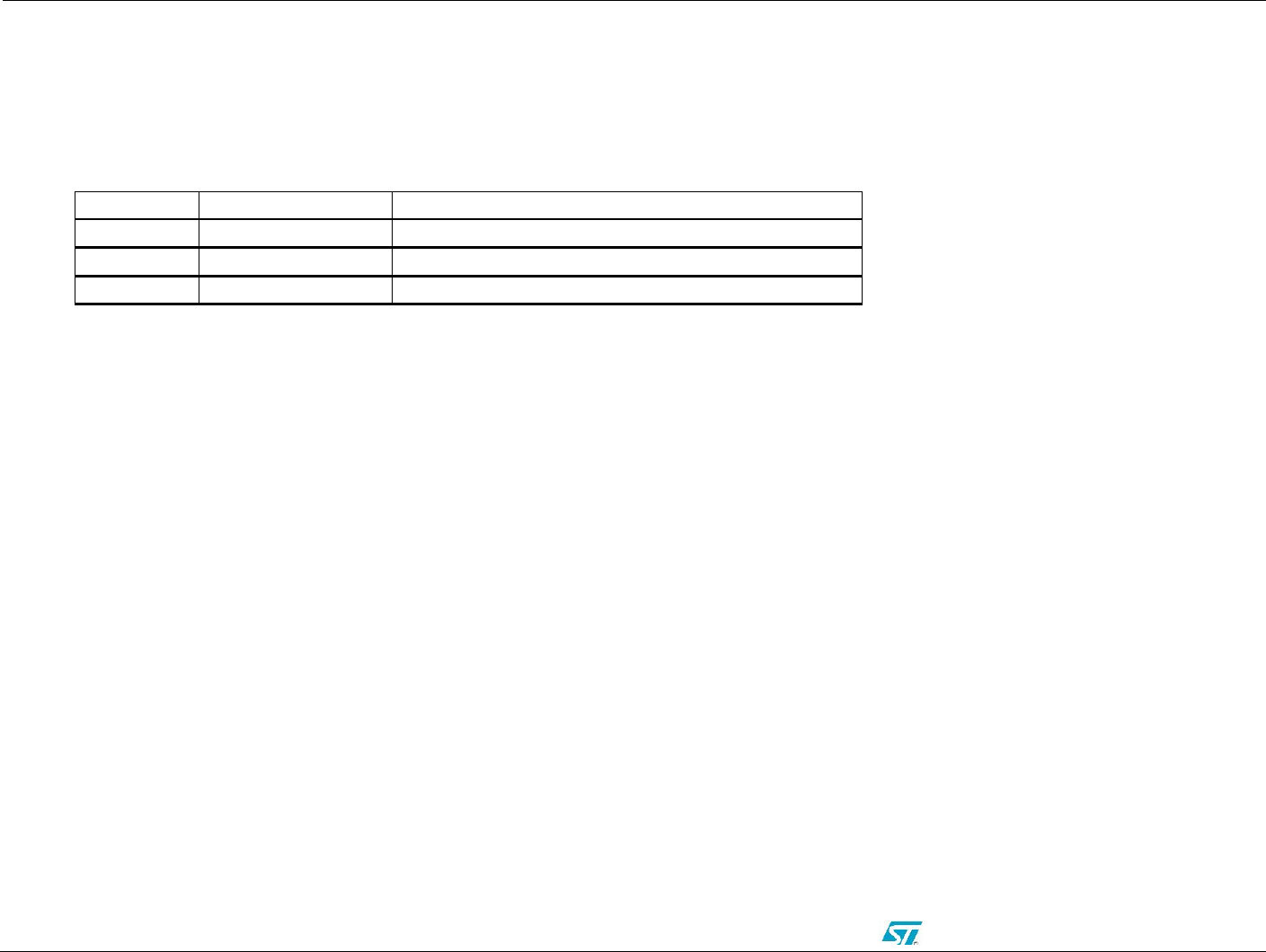
6 Revision history
Table 1: Table Title
Revision
Date of modification
Description of modification
0.2
July 15
Initial draft
0.3
July 15
Modified version
0.4
July 15
Changed name in STEVAL-WESU1

ST application note template Error! No text of specified style in document.
STMicroelectronics Confidential Rev 0.1 21/22
DRAFT

Error! No text of specified style in document. ST application note template
22/22 Version 0.1 STMicroelectronics Confidential
DRAFT
Please Read Carefully:
Information in this document is provided solely in connection with ST products. STMicroelectronics NV and its subsidiaries (“ST”) reserve the right to make changes, corrections, modifications or improvements, to
this document, and the products and services described herein at any time, without notice.
All ST products are sold pursuant to ST’s terms and conditions of sale.
Purchasers are solely responsible for the choice, selection and use of the ST products and services described herein, and ST assumes no liability whatsoever relating to the choice, selection or use of the ST
products and services described herein.
No license, express or implied, by estoppel or otherwise, to any intellectual property rights is granted under this document. If any part of this document refers to any third party products or services it shall not be
deemed a license grant by ST for the use of such third party products or services, or any intellectual property contained therein or considered as a warranty covering the use in any manner whatsoever of such
third party products or services or any intellectual property contained therein.
UNLESS OTHERWISE SET FORTH IN ST’S TERMS AND CONDITIONS OF SALE ST DISCLAIMS ANY EXPRESS OR IMPLIED WARRANTY WITH RESPECT TO THE USE AND/OR SALE OF ST
PRODUCTS INCLUDING WITHOUT LIMITATION IMPLIED WARRANTIES OF MERCHANTABILITY, FITNESS FOR A PARTICULAR PURPOSE (AND THEIR EQUIVALENTS UNDER THE LAWS OF ANY
JURISDICTION), OR INFRINGEMENT OF ANY PATENT, COPYRIGHT OR OTHER INTELLECTUAL PROPERTY RIGHT. UNLESS EXPRESSLY APPROVED IN WRITING BY AN AUTHORIZE
REPRESENTATIVE OF ST, ST PRODUCTS ARE NOT DESIGNED, AUTHORIZED OR WARRANTED FOR USE IN MILITARY, AIR CRAFT, SPACE, LIFE SAVING, OR LIFE SUSTAINING APPLICATIONS,
NOR IN PRODUCTS OR SYSTEMS, WHERE FAILURE OR MALFUNCTION MAY RESULT IN PERSONAL INJURY, DEATH, OR SEVERE PROPERTY OR ENVIRONMENTAL DAMAGE.
Resale of ST products with provisions different from the statements and/or technical features set forth in this document shall immediately void any warranty granted by ST for the ST product or service described
herein and shall not create or extend in any manner whatsoever, any liability of ST.
ST and the ST logo are trademarks or registered trademarks of ST in various countries.
Information in this document supersedes and replaces all information previously supplied.
The ST logo is a registered trademark of STMicroelectronics. All other names are the property of their respective owners.
© 2006 STMicroelectronics - All rights reserved
STMicroelectronics group of companies
Australia - Belgium - Brazil - Canada - China - Czech Republic - Finland - France - Germany - Hong Kong - India - Israel - Italy - Japan -
Malaysia - Malta - Morocco - Singapore - Spain - Sweden - Switzerland - United Kingdom - United States of America
www.st.com