STAR MICRONICS SM-L300 Portable Thermal Printer User Manual
STAR MICRONICS CO., LTD. Portable Thermal Printer
UserManual.wiki
>
STAR MICRONICS
>
SM L300 User Manual
User Manual
Navigation menu
Upload a User Manual
Namespaces
Wiki Guide
HTML
PDF
Info
Views
User Manual
Discussion / Help
Navigation
![équipement émet une énergie RF très faible qui est considérée conforme sans évaluation de l"exposition maximale autorisée. Cependant, cet équipement doit être installé et utilisé en gardant une distance de 20 cm ou plus entre le dispositif rayonnant et le corps (à l"exception des extrémités : mains, poignets, pieds et chevilles) The above statement applies only to equipments marketed in U.S.A. <Europe model> English: Hereby, STAR MICRONICS CO.,LTD. declares that this Wireless Device is in compliance with the essential requirements and other relevant provisions of Directive 2014/53/EU. Deutsch: [German] Hiermit erklärt STAR MICRONICS CO.,LTD., dass sich das Gerät Wireless Device in Übereinstimmung mit den grundlegenden Anforderungen und den übrigen einschlägigen Bestimmungen der Richtlinie 2014/53/EU befidet. Svenska: [Swedish] Härmed intygar STAR MICRONICS CO.,LTD. att denna Wireless Device står I överensstämmelse med de väsentliga egenskapskravoch övriga relevanta bestämmelser som framgår av direktiv 2014/53/EU. Español: [Spanish] Por medio de la presente STAR MICRONICS CO.,LTD. declara que el Wireless Device cumple con los requisitos esenciales y cualesquiera otras disposiciones aplicables o exigibles de la Directiva 2014/53/UE. Português: [Portuguese] STAR MICRONICS CO.,LTD. declara que este Wireless Device está conforme com os requisitos essenciais e outras disposições da Directiva 2014/53/UE. Français: [French] Par la présente STAR MICRONICS CO.,LTD. déclare que l’appareil Wireless Device est conforme aux exigences essentielles et aux autres dispositions pertinentes de la directive 2014/53/UE. Suomi: [Finnish] STAR MICRONICS CO.,LTD. vakuuttaa täten että Wireless Device tyyppinen laite on direktiivin 2014/53/EU oleellisten vaatimusten jasitä koskevien direktiivin muiden ehtojen mukainen. Italiano: [Italian] Con la presente STAR MICRONICS CO.,LTD. dichiara che questo Wireless Device è conforme ai requisiti essenziali ed alle altre disposizioni pertinenti stabilite dalla direttiva 2014/53/UE. Dansk: [Danish] Undertegnede STAR MICRONICS CO.,LTD. erklærer herved, at følgende udstyr Wireless Device overholder de væsentlige krav og øvrige relevante krav i direktiv 2014/53/EU. Nederlands: [Dutch] Hierbij verklaart STAR MICRONICS CO.,LTD. dat het toestel Wireless Device in overeenstemming is met de essentiële eisen en de andere relevante bepalingen van richtlijn 2014/53/EU. Eesti: [Estonian] Käesolevaga kinnitab STAR MICRONICS CO.,LTD. seadme Wireless Device vastavust direktiivi 2014/53/EL põhinõuetele ja nimetatud direktiivist tulenevatele teistele asjakohastele sätetele. Ελληνική: [Greek] ΜΕ ΤΗΝ ΠΑΡΟΥΣΑ STAR MICRONICS CO.,LTD. ΔΗΛΩΝΕΙ ΟΤΙ Wireless Device ΣΥΜΜΟΡΦΩΝΕΤΑΙ ΠΡΟΣ ΤΙΣ ΟΥΣΙΩΔΕΙΣ ΑΠΑΙΤΗΣΕΙΣΚΑΙ ΤΙΣ ΛΟΙΠΕΣ ΣΧΕΤΙΚΕΣ ΔΙΑΤΑΞΕΙΣ ΤΗΣ ΟΔΗΓΙΑΣ 2014/53/EE. Slovensky: [Slovak] STAR MICRONICS CO.,LTD. týmto vyhlasuje, že Wireless Device spĺňa základné požiadavky a všetky príslušné ustanovenia Smernice 2014/53/EÚ. Slovensko: [Slovenian] STAR MICRONICS CO.,LTD. izjavlja, da je ta Wireless Device v skladu z bistvenimi zahtevami in ostalimi relevantnimi določili direktive 2014/53/EU. Česky: [Czech] STAR MICRONICS CO.,LTD. tímto prohlašuje, že tento Wireless Device je ve shodě se základními požadavky a dalšími príslušnými ustanoveními smernice 2014/53/EU. Magyar: [Hungarian] Alulírott, STAR MICRONICS CO.,LTD. nyilatkozom, hogy a Wireless Device megfelel a vonatkozó alapvetõ követelményeknek és az 2014/53/EU irányelv egyéb elõírásainak. Български: [Bulgarian] това Безжично устройство е в съответствие със задължителните изисквания и другите приложими разпоредби на Директива2014/53/EC. Polski: [Polish] Niniejszym STAR MICRONICS CO.,LTD. oświadcza, że Wireless Device jest zgodny z zasadniczymi wymogami oraz pozostałymi stosownymi postanowieniami Dyrektywy 2014/53/UE. Malti: Hawnhekk, STAR MICRONICS CO.,LTD., jiddikjara li dan Wireless Device jikkonforma mal-ħtiġijiet](https://usermanual.wiki/STAR-MICRONICS/SM-L300/User-Guide-3218455-Page-3.png)
![[Maltese] essenzjali u ma provvedimenti oħrajn relevanti li hemm fid-Dirrettiva 2014/53/UE. Latviski: [Latvian] Ar šo STAR MICRONICS CO.,LTD. deklarē, ka Wireless Device atbilst Direktīvas 2014/53/ES būtiskajām prasībām un citiem ar to saistītajiem noteikumiem. Lietuvių : [Lithuanian] Šiuo STAR MICRONICS CO.,LTD. deklaruoja, kad šis Wireless Device atitinka esminius reikalavimus ir kitas 2014/53/ES Direktyvos nuostatas. Norsk: [Norwegian] STAR MICRONICS CO.,LTD. erklærer herved at utstyret Wireless Device er i samsvar med de grunnleggende krav og øvrige relevante krav i direktiv 2014/53/EC. Română : [Romanian] Prin prezenta STAR MICRONICS CO., LTD. declară că acest dispozitiv este conform cu cerinţele esenţiale și alte prevederi relevante ale directivei 2014/53/UE. Hrvatski : [Croatian] Ovime Star Micronics CO., LTD. Izjavljuje da je bežični uređaj u skladu s osnovnim zahtjevima i drugim važnim odredbama direktive 2014/53/EU. Italy: The public use is subject to general authorisation by the respective service provider. Norway: This subsection does not apply for the geographical area within a radius of 20 km from the centre of Ny-Ålesund. Trademark acknowledgments SM-L300: Star Micronics Co., Ltd. Notice All rights reserved. Reproduction of any part of this manual in any form whatsoever, without STAR’s express permission is forbidden. The contents of this manual are subject to change without notice. All efforts have been made to ensure the accuracy of the contents of this manual at the time of going to press. However, should any errors be detected, STAR would greatly appreciate being informed of them. The above notwithstanding, STAR can assume no responsibility for any errors in this manual. iPad, iPhone, iPod, iPod touch, and Retina are trademarks of Apple Inc., registered in the U.S. and other countries. iPad Air, iPad mini, and Lightning are trademarks of Apple Inc. IOS is a trademark or registered trademark of Cisco in the U.S. and other countries and is used under license. Android is a trademark of Google Inc.](https://usermanual.wiki/STAR-MICRONICS/SM-L300/User-Guide-3218455-Page-4.png)
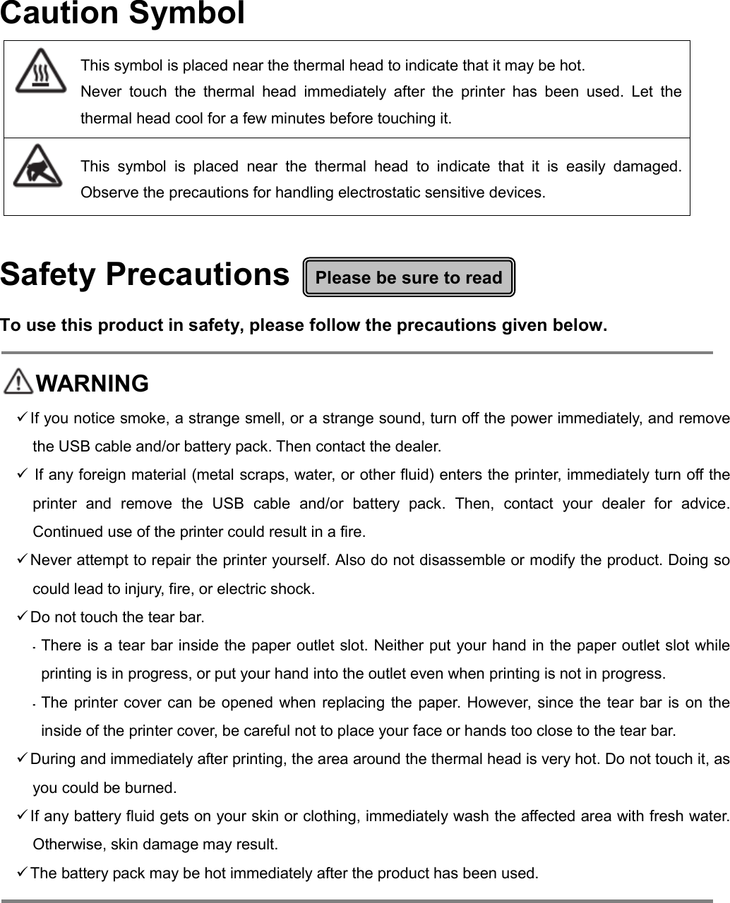
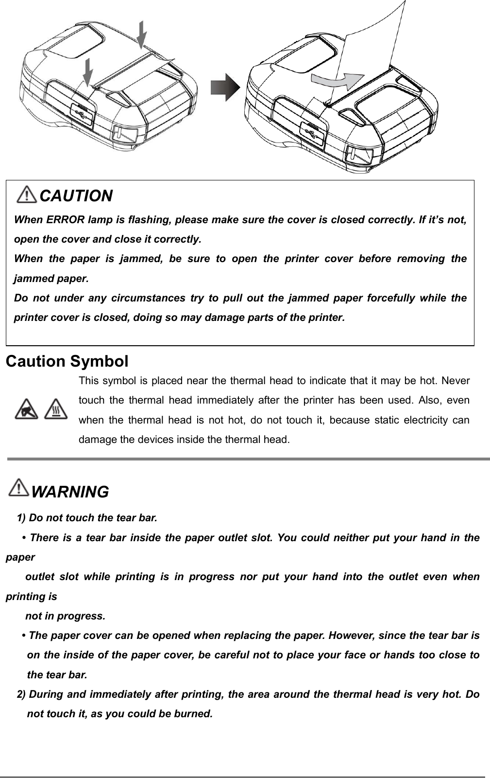
![ Using the Printer Some semiconductors can be damaged by static electricity. Be sure to turn off the printer when inserting or removing the battery pack. Do not drop the printer or hit it against a hard object. Do not open the printer cover while the printer is printing. Before you open the printer cover, make sure that printing data is not being sent to the printer. Do not unplug or plug in a USB cable while the printer is printing or during communication. Do not touch a USB connector while the printer is printing. Turn off the printer when you are not using it. When the printer is used in a low temperature environment, the battery's performance will be diminished, and the amount of time that you can use the printer for may be reduced. Do not pull out paper while the printer cover is closed. The heating element and the driver IC of the thermal head are easily damaged. Do not touch them with metal objects, sandpaper, etc. Printing quality may suffer if the thermal head heating element becomes soiled by being touched with your hands. Do not touch the thermal head heating element. There is a risk of damage to the driver IC of the thermal head from static electricity. Never directly touch the IC. Do not operate the printer if there is moisture on the front surface of the head from condensation, etc. Thermal Paper Handling Only use thermal paper with the designated specifications. The printing quality and working life of the thermal head cannot be guaranteed if any paper other than that recommended is used. In particular, if ion concentration of [Na+, K+, Cl-] is high, it may drastically reduce the working life of the thermal head. Please exercise caution. Store the thermal paper in a cool, dry, dark location. Do not rub the thermal paper with a hard object. Do not leave the thermal paper in contact with plastic film, an eraser, or adhesive tape for a long period of time. Do not stack the thermal paper on fresh diazo copies or wet-type copies. Do not use chemical glue on the thermal paper. Do not use thermal paper that has been stored for a long period.](https://usermanual.wiki/STAR-MICRONICS/SM-L300/User-Guide-3218455-Page-7.png)
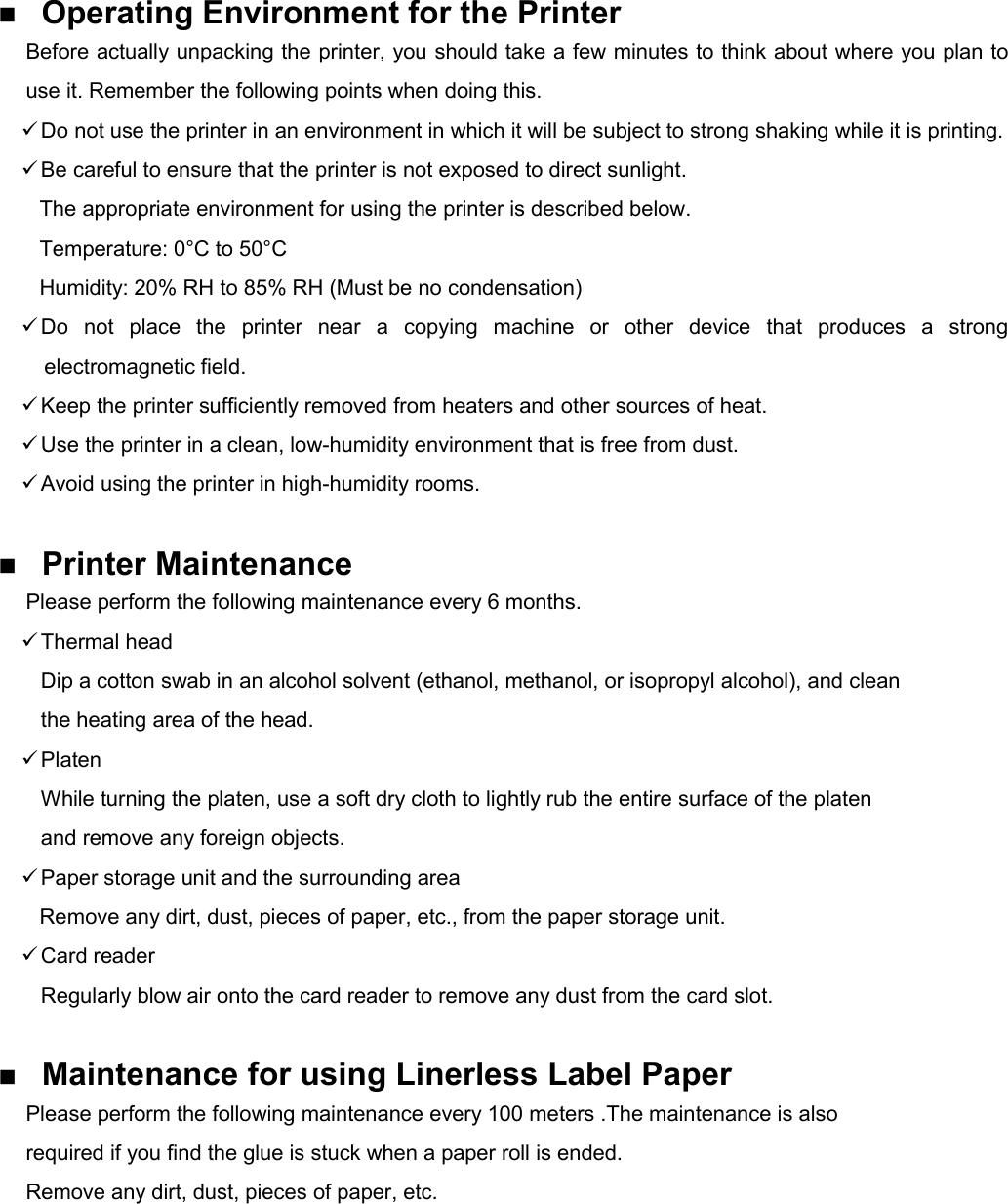
![1. Product Overview This printer is perfect for mobile banking systems, retail, POS (point of sale) terminals and other forms of mobile computing. The characteristics of this printer are listed below: • Support Adhesive Label Paper and Linerless Label paper • Support to switch the de-curl function when receipt is used. • Adjustable range of Roll Paper Width : 40 to 80mm • Very silent printing direct thermal printing method • Print maximum speed 65mm/s (Paper feed maximum speed 65mm/s) • Support Bluetooth Ver3.0/4.0[BLE] Dual Mode • Support Secure Magnetic Stripe Reader <Model with Card Reader> *AES or 3DES encryption *DUKPT Key Management • Support Graphic LCD(128x64 dots) with Blue Backlight • Belt Clip as a standard accessory • Support text, barcode and graphic printing • Drop-in design that makes it easy to load paper • This printer is supported with the printer cover open sensor, paper end sensor, black mark sensor, transmissive sensor(gap sensor), thermal head thermister and printer internal thermister.](https://usermanual.wiki/STAR-MICRONICS/SM-L300/User-Guide-3218455-Page-12.png)
![2.2 Bluetooth 2.2.1 Pairing 1. Press and hold MODE button for approx. 2 seconds, and printer is turned on. Then, it is ready to pair with another Bluetooth device. 2. Select the device name and enter the PIN code as shown below. PIN: 1234 (default) Device name: “STAR L300-XXXXX”(default) (XXXXX is the last digits of the Product Serial Number. The device name displayed during pairing varies depending on the product. It can be checked from the [BD Name] that is printed when printer self-printing is performed (power is turned ON while depressing the FEED button). Notes: 1.SM-L300 has two Bluetooth modes: a) One is Bluetooth Ver3.0 with PIN for Android or Windows system. PIN and Device name can be changed through Star Utility. To obtain this utility, please contact with your dealer. b) Another is Bluetooth 4.0(BLE) without PIN for iOS system. 2.SM-L300 changes the Bluetooth mode automatically by host system. 3.Pairing sets one by one in order, otherwise it can‘t figure out which one succeeds in pairing. You can test the connectivity with a host device by using Star IO SDK Application which is available on Apple Store and Google play. The Bluetooth® word mark and logos are owned by the Bluetooth SIG, Inc. and any use of such marks by Star is under license.(Design and specifications subject to change without notice.)](https://usermanual.wiki/STAR-MICRONICS/SM-L300/User-Guide-3218455-Page-20.png)
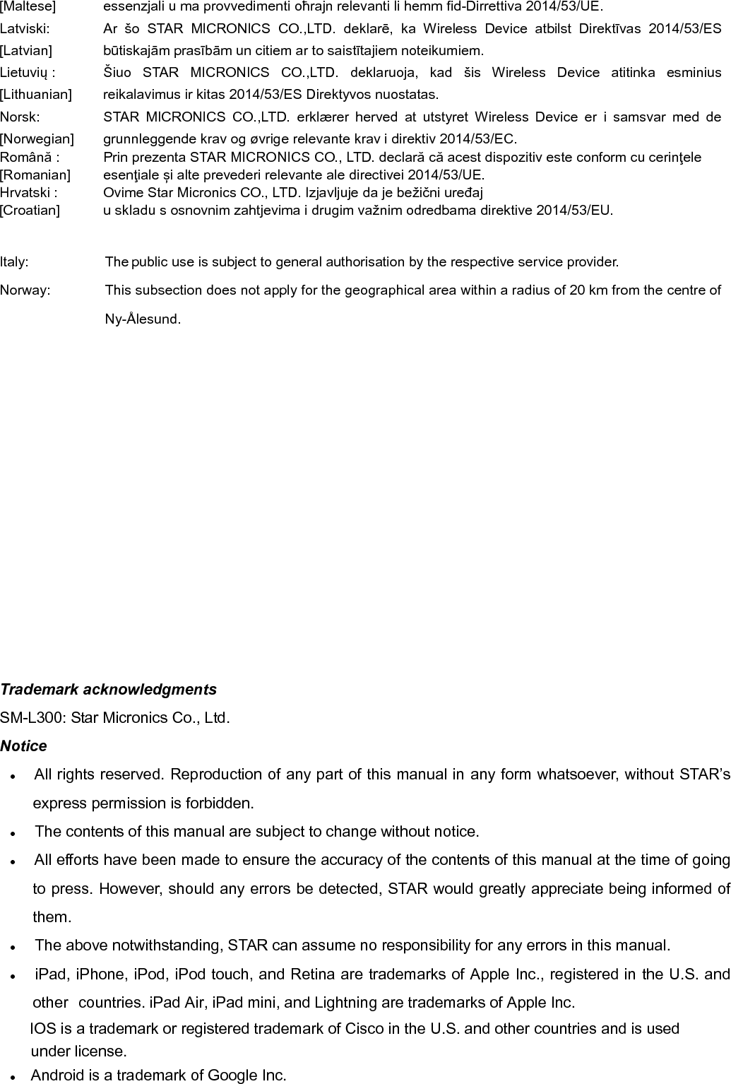
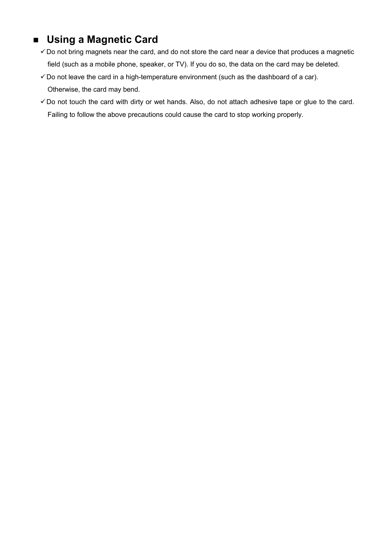
![3.2 LED & LCD Display / Error 3.2.1 LED & LCD Display Table1-1 Status Action Lamp LCD LCD back Light, [Discription] Buzzer Power (Green) Error (Red) Printer Initialization(Power On) ON OFF Backlight ON [Printer Status:Online] Beep (A->B->C) Power OFF USB Cable is not connected OFF OFF Backlight OFF Beep (D->E->F) USB Cable is connected Battery Full OFF OFF Backlight OFF Battery Empty Flashing OFF Backlight OFF On-Line (Idle) Bluetooth (COM) USB Cable is not connected Bluetooth connected ON OFF Backlight ON Maintain the original state Bluetooth Icon ON Nothing Bluetooth disconnected ON OFF Backlight ON maintain the original state Bluetooth Icon OFF Nothing Stand-by 1sec Flashing OFF Backlight OFF Nothing Return from Stand-by ON OFF Backlight ON maintain the original state Nothing USB USB Cable is connected Normal Battery Full ON OFF Backlight ON maintain the original state Battery Icon Battery Full Icon Nothing Battery is not Full 600ms Flashing OFF Backlight ON maintain the original state Battery Icon Charge Icon Beep (G) Stand-by 1sec Flashing OFF Backlight OFF Nothing Return from Stand-by ON OFF Backlight ON maintain the original state Nothing Taking off cable Normal Battery Full ON OFF Backlight ON maintain the original state Battery Icon Battery Full Icon Nothing](https://usermanual.wiki/STAR-MICRONICS/SM-L300/User-Guide-3218455-Page-28.png)
![Table1-2 Status Action Lamp LCD LCD back Light, [Discription] Buzzer Power (Green) Error (Red) On-Line (Idle) USB Taking off cable Battery is not Full 600ms Flashing =>ON OFF Backlight ON maintain the original state Battery Icon Charge Icon Beep (G->G->G) Stand-by 1sec Flashing OFF Backlight OFF Nothing Return from Stand-by ON OFF Backlight ON maintain the original state Nothing MSR Mode Waiting for swiping ON OFF Backlight ON [] Nothing Stand-by ON OFF Backlight ON maintain the original state Nothing Succeeded decoding ON OFF Backlight ON maintain the original state Beep (G) Failed decoding ON OFF Backlight ON maintain the original state Beep (G->G->G) Receiving Data Printing Data (Including busy state) ON OFF Backlight ON [Printing…] Nothing Other ON OFF Backlight ON maintain the original state Nothing Menu Operation Mode Enter Menu Operation Mode ON OFF Backlight ON [Enter Menu Mode] Beep (G-.G) While Menu Operation Mode Backlight ON maintain the original state When push the button Beep(G) Get out Menu Operation Mode Backlight ON maintain the original state Nothing Self Test Printing Before printing ON OFF Backlight ON [Press Feed To Print] Nothing While printing Backlight ON [Printing…] Nothing After printing Backlight ON Self test menu Nothing MSR Reading MSR Online ON OFF Backlight ON [Please Swipe Card] Nothing Error ON Flashing Backlight ON [Printer not ready...] Nothing Succeeded decoding ON OFF Backlight ON [Please Swipe Card] Beep (G) Failed decoding Backlight ON [Please Swipe Card] Beep (G-G)](https://usermanual.wiki/STAR-MICRONICS/SM-L300/User-Guide-3218455-Page-29.png)
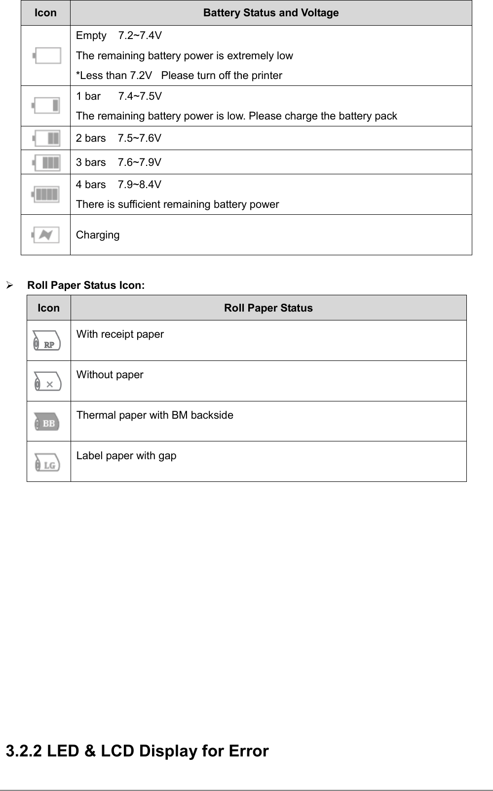
![Table1-3 Status Action Lamp LCD LCD back Light, [Discription] Buzzer Power (Green) Error (Red) MSR Injecting key Online ON OFF Backlight ON [Please Inject Key...] Nothing Succeeded key injection Backlight ON [Key Injection:Success] Beep (G) Failed key injection Backlight ON [Key Injection:Error] Beep (G-G) Hex Dump Mode ON OFF Backlight ON [Hex Dump Mode] Nothing Self Test Printing at the button operation While printing ON OFF Backlight ON [Printing…] Nothing After printing Backlight ON maintain the original state Nothing Writing Firmware Enter Writing Mode ON OFF Backlight OFF Nothing While Writing Backlight OFF Nothing Finish Writing Backlight OFF (Power is also OFF) Nothing Notes: a) Bluetooth Status icon, Battery status icon and Roll paper Status Icon are always displayed on LCD when Blacklight is ON. b) Buzzer sound frequency or pattern A : 530Hz/192msec E : 667Hz/96msec B : 670Hz/192msec F : 537Hz/96msec C : 800Hz/192msec G : 800Hz/96msec D : 800Hz/96msec Bluetooth Status Icon: Icon Bluetooth Status No Bluetooth connection Bluetooth connection Battery Status Icon:](https://usermanual.wiki/STAR-MICRONICS/SM-L300/User-Guide-3218455-Page-30.png)
![Status Action Lamp LCD LCD back Light, [Discription] Buzzer Power (Green) Error (Red) Error Recoverable Error *Buffer is cleared. No paper error Happened ON Flashing Backlight ON [Printer Status:Out of Paper] Roll paper Icon without paper Beep (G->G) Recovered ON OFF Backlight ON [Printer Status:Online] Roll paper Icon maintain the original state Beep (G) Cover open error Happened ON Flashing Backlight ON [Printer Status:Cover Open] Beep (G->G) Recovered ON Depend on paper Flashing or OFF Backlight ON maintain the original state Beep (G) Black Mark Sensor error ON Flashing Backlight ON [Printer Status: Black Mark Error] Beep (G->G) Gap Sensor error (Transmissive Sensor error) ON Flashing Backlight ON [Printer Status: Gap Sensor Error] Beep (G->G) Auto Recoverable Error Heat Protection of Thermal Printer Head Happened ON Flashing Backlight ON [TPH Thermistor detecting] Nothing Recovered ON OFF Backlight ON [TPH Thermistor detecting] Nothing Unrecoverable Error MSR error ON Flashing Backlight ON [Printer Status:MSR Error] Beep (G->G->G) Black Mark Sensor Adjustment error ON Flashing Backlight ON [Printer Status:BM Adjust Error] Beep (G->G->G) Gap Sensor Adjustment error (Transmissive Sensor Adjustment error) ON Flashing Backlight ON [Printer Status:Gap Adjust Error] Beep (G->G->G) Thermal Head Thermister error ON Flashing Backlight ON [Printer Status:ThermalHead[Error] Beep (G->G->G) Printer Internal Thermister error ON Flashing Backlight ON [Printer Status:Priter Error] Beep (G->G->G) Notes: a) Bluetooth Status icon, Battery status icon and Roll paper Status Icon are always displayed on LCD when Blacklight is ON. b) Buzzer sound frequency or pattern](https://usermanual.wiki/STAR-MICRONICS/SM-L300/User-Guide-3218455-Page-32.png)

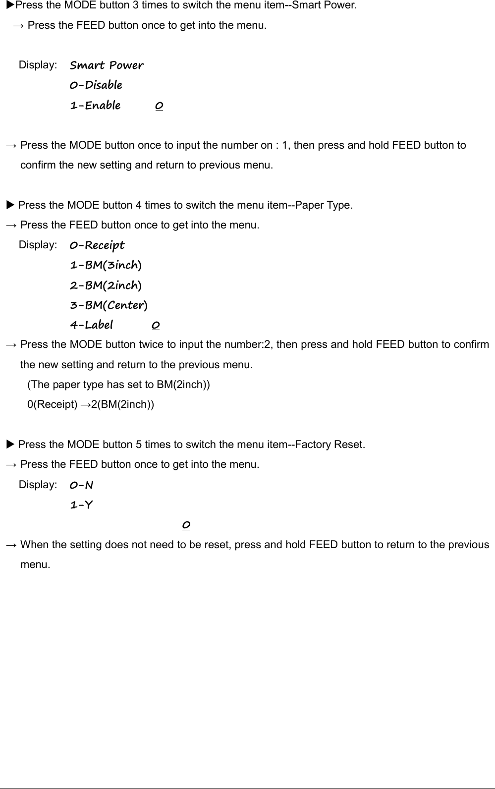
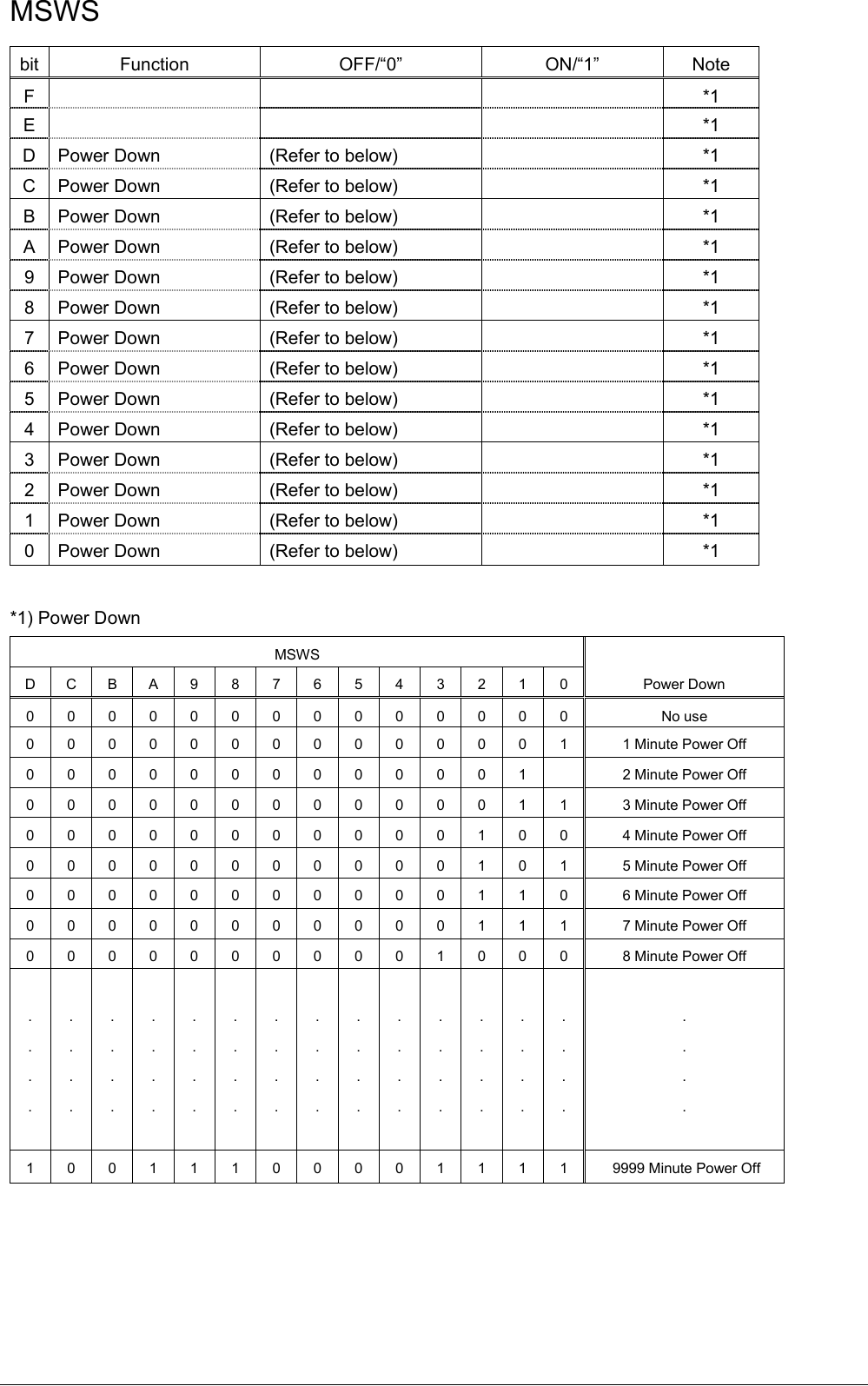
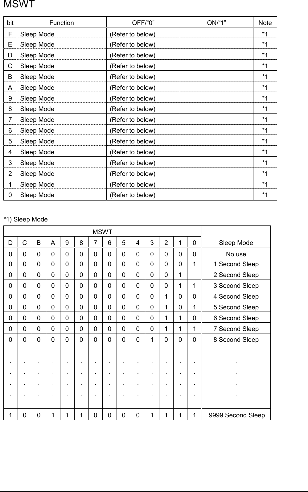
![ Press MODE button to switch the menu item, then press the FEED button once to enter the menu. → Press the FEED button once to get into the Density menu. Display: Density: 0-Medium 1-Low 2-High 3-Special 0 → Press the MODE button once to input the number 1, then press and hold FEED button to confirm the new setting and return to the previous menu. (The density has set to Low) 0(Medium) → 1(Low) Press the MODE button once to switch the menu item--Standby Time. → Press the FEED button once to get into the menu. Display: Standby Time: [0010-9999(Sec)] 0060 → Press the FEED button twice to move cursor(“-”), then press the MODE button twice to input the number: 8, finally press and hold FEED button to confirm the new setting and return to the previous menu. (The standby time has set to 80 seconds) 0060(Sec) →0080(Sec) When set the parameter to 0000, the standby time becomes invalid. If set the parameter to 0001~ 0009, a buzzer beeps, so do not set it. Press the MODE button twice to switch the menu item--Auto Off Time. → Press the FEED button once to get into the menu. Display: Auto Off Time: [0000-9999(Min)] 0000 → Press the MODE button once to input the number on : 1, then press and hold FEED button to confirm the new setting and return to previous menu. (The auto off time has set to 1000 minutes) 0000(Min) →1000(Min) When set the parameter to 0000, the auto off time becomes invalid.](https://usermanual.wiki/STAR-MICRONICS/SM-L300/User-Guide-3218455-Page-37.png)
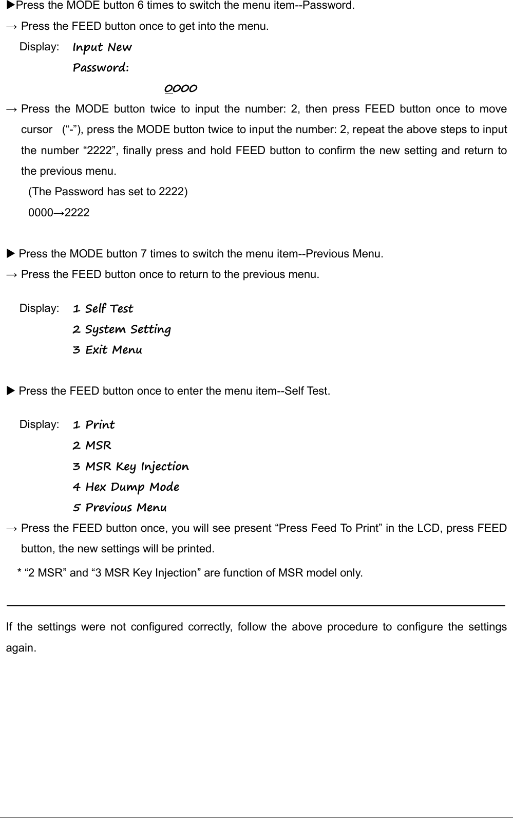
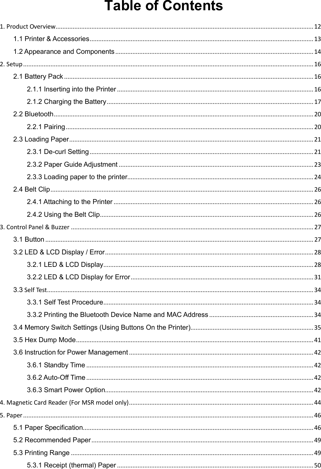
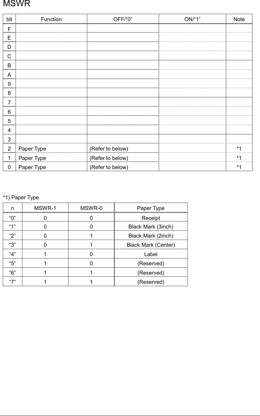
![Memory Switch Setting Table First-level menu Second-level menu Third-level menu Fourth-level menu Default 1 Self Test 1 Print Press Feed To Print -- -- 2 MSR MSR SELF TEST Please Swipe Card -- 3 MSR Key Injection*1 MSR Key Injection Please Inject Key - 4 Hex Dump Mode*1 Hex Dump Mode -- -- 5 Previous Menu -- -- -- 2 System Setting Input Password: 0000 1 Density 0-Medium 1-Low 2-High 3-Special -- Medium 2 Standby Time Standby Time: [0010-9999(Sec)] -- 60 Seconds 3 Auto Off Time Auto Off Time: [0001-9999(Min)] -- 0000 4 Smart Power Smart Power 0-Disable 1-Enable -- 0 5 Paper Type 0-Receipt 1-BM(3inch) 2-BM(2inch) 3-BM(Center) 4-Label -- Receipt 6 Factory Reset 0-N 1-Y -- N 7 Password Input New Password: 0000 -- 0000 8 Previous Menu -- -- -- 3 Exit Menu -- -- -- *1) “2 MSR” and “3 MSR Key Injection” are function of MSR model only.](https://usermanual.wiki/STAR-MICRONICS/SM-L300/User-Guide-3218455-Page-40.png)
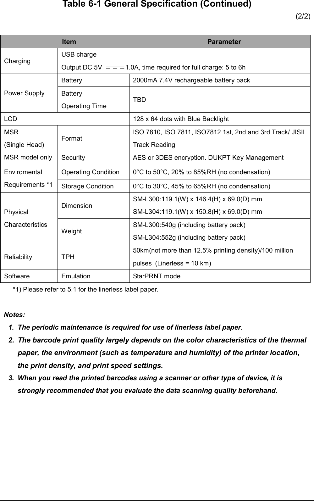
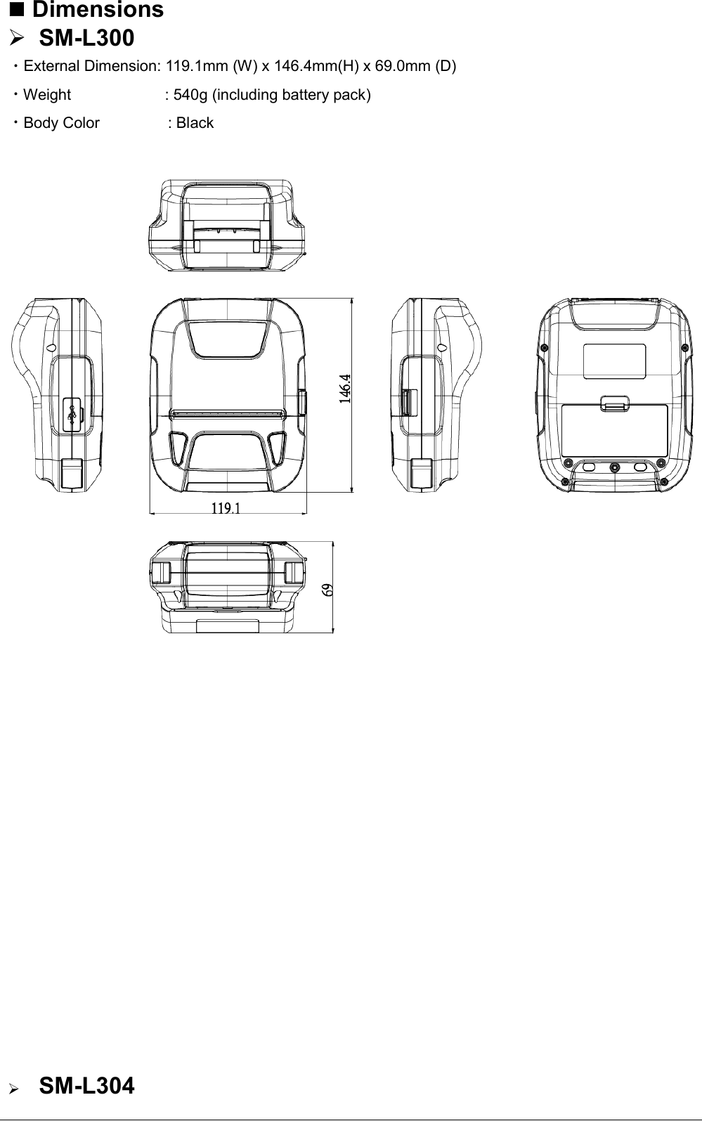
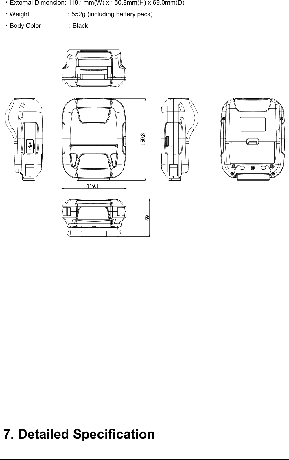
![6. General Specification Table 6-1 General Specification (1/2) Item Specifications Printing Printing Method Direct line thermal printing Resolution 203dpi (8dots/mm) Printing Speed Max.65mm/s Valid Printing Width Max.72mm Interface Bluetooth Specification Communication Bluetooth Ver 3.0/4.0 [BLE] Dual Mode Frequency Range 2.4GHz ISM-band Data Transmission Rate 115200bps adjustable Data Bit 8 data bit fixed Parity Bit No parity fixed Stop Bit 1 stop bit fixed SSP Compatible USB Micro-USB Power Saving Stand-by YES Character Set Font Alphanumeric: 9x17, 9x24, 12x24 dots Kanji: 24x24 dots Barcode Symbologies 1D UPC-A, UPC-E, JAN/EAN8, JAN/EAN13, CODE39, ITF, CODE128, CODE93, CODABAR(NW-7), GS1-128, GS1 Omnidirectional, GS1 Truncated, GS1 Limited, GS1 Expanded 2D QR code(Support 15mm), PDF417, GS1 Stacked, GS1 Stacked Omnidirectional, GS1 Expanded Stacked, GS1 Composite Symbols Graphics Support bitmap printing with different density and user defined bitmap printing (Max. 512K for total) Detection Sensors Cover open sensor, Paper end sensor, Black mark sensor, Transmissive sensor(Label Gap sensor), Thermal head thermister, Printer internal thermister LED Power Lamp Green Error Lamp Red Drop resistance 1.2m](https://usermanual.wiki/STAR-MICRONICS/SM-L300/User-Guide-3218455-Page-53.png)
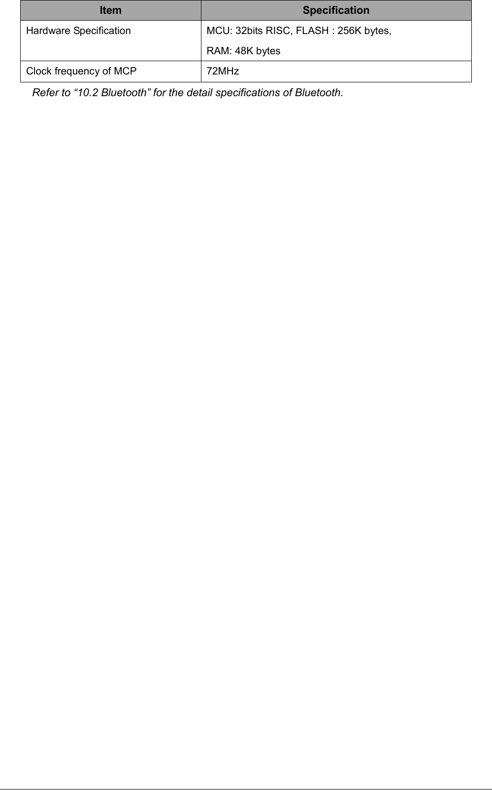
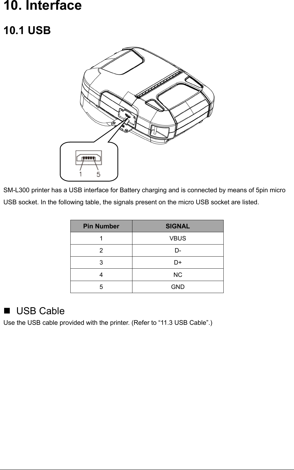
![10.2 Bluetooth Category Specification Bluetooth Spec. Bluetooth Ver 3.0/4.0 [BLE] Dual Mode) Class2 (10m) Frequency Range 2.4GHz ISM band Data Transmission Rate 115200bps adjustable Data Bit 8 data bit fixed Parity Bit No parity fixed Stop Bit 1 stop bit fixed SSP Compatible PIN code: 1234 as default for Android/Windows. (Bluetooth Ver.3.0) Device Name: STAR L300-XXXXX Device Name: STAR L304-XXXXX MSR model (XXXXX is the last 5 digits of the Product Serial Number)](https://usermanual.wiki/STAR-MICRONICS/SM-L300/User-Guide-3218455-Page-75.png)