STEELMATE BT0001 LCD TWO WAY REMOTE CONTROLLER User Manual sp 500 ins
STEELMATE CO., LTD. LCD TWO WAY REMOTE CONTROLLER sp 500 ins
UserManual.wiki
>
STEELMATE
>
BT0001 User Manual
USERS MANUAL
Navigation menu
Upload a User Manual
Namespaces
Wiki Guide
HTML
PDF
Info
Views
User Manual
Discussion / Help
Navigation
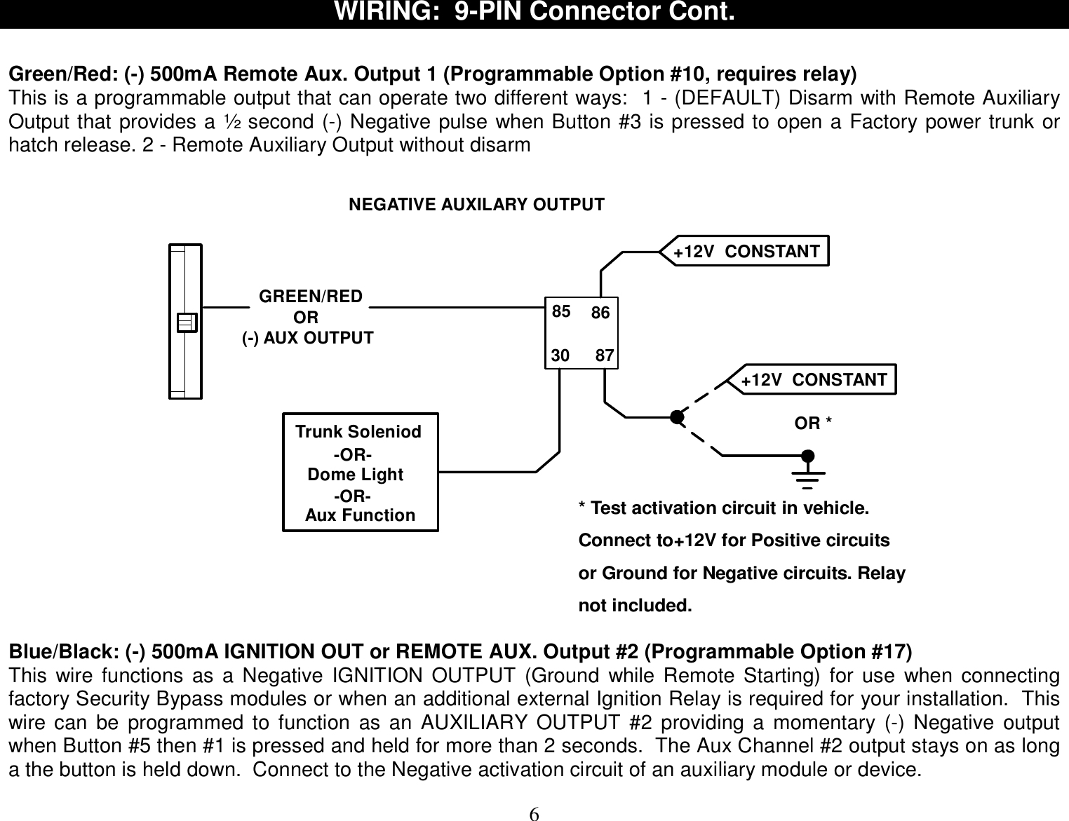
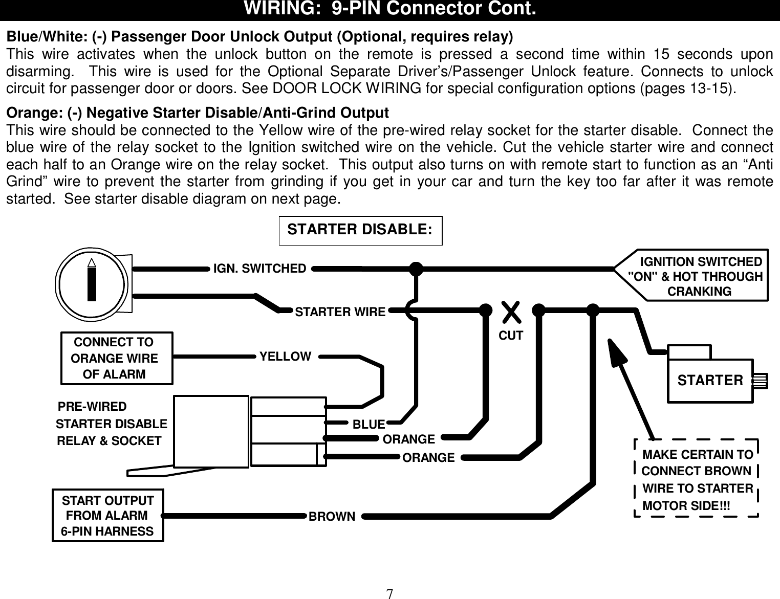
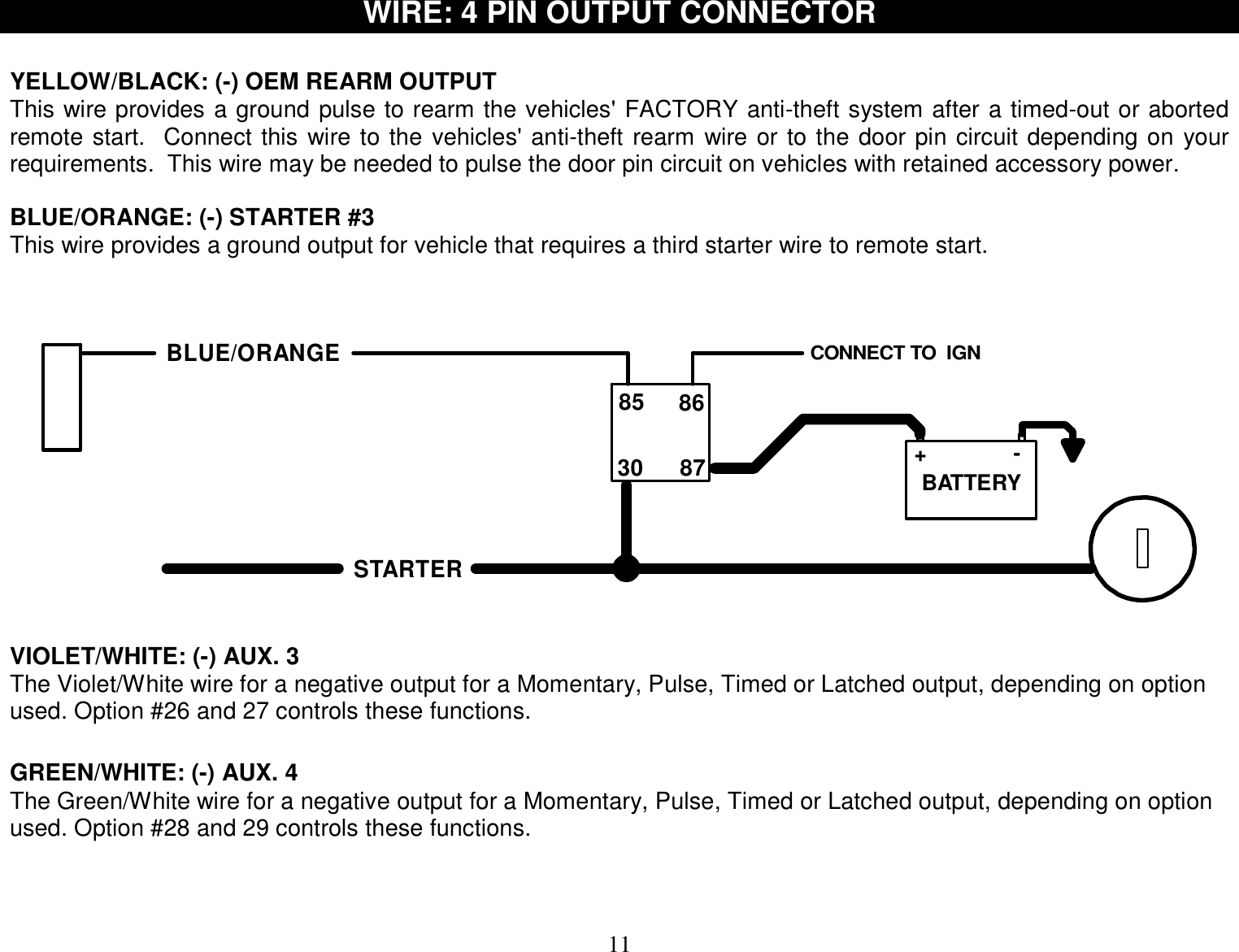
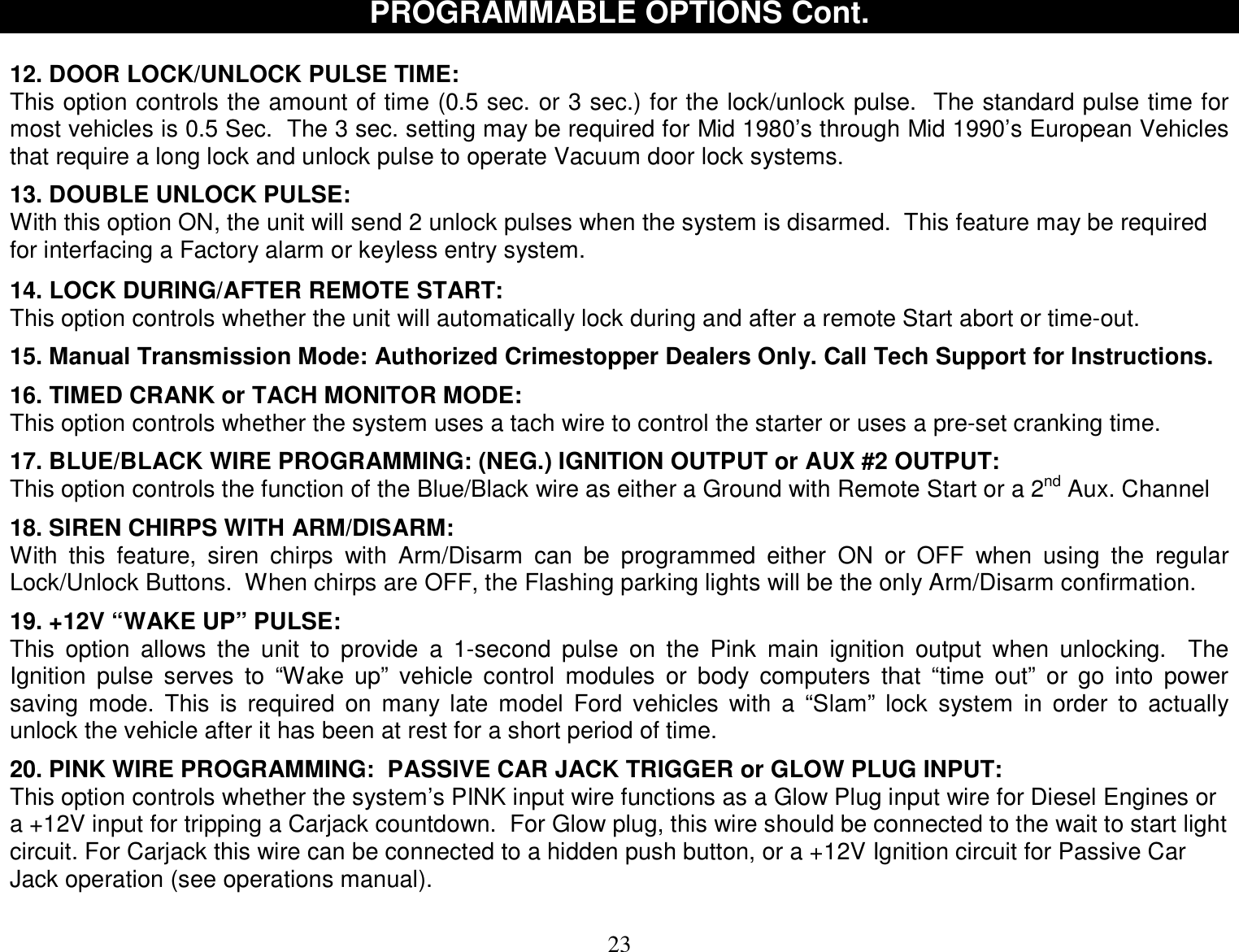
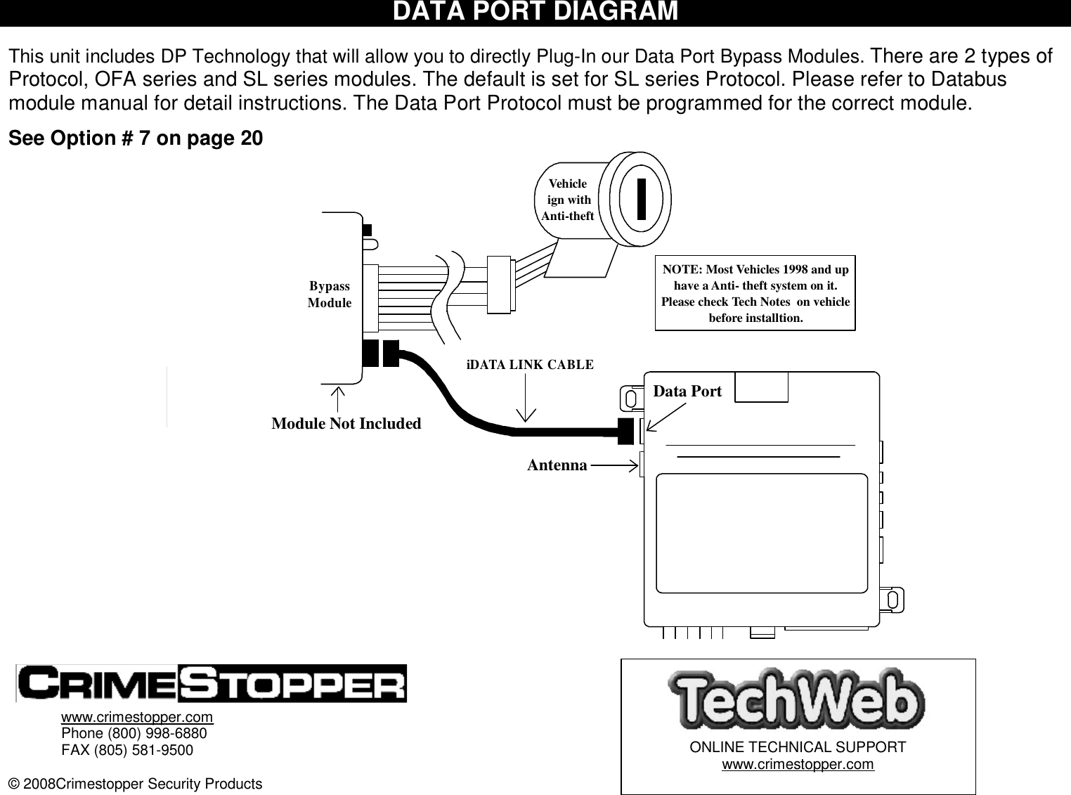
![5 MomentarySwitchGREENOptional Turbo Timer Wiring(Not included) WIRING: 9-PIN Connector Green: MODE A: (-) Start Activation Input This wire allows an outside source or accessory to activate a Remote Start. A 1-second Ground pulse on this wire will trigger a remote start. This wire can be used with an RS-400 temperature module. Green: MODE B (-) Optional Turbo Timer Input (3 Modes, Option #30) This wire allows the system to keep a vehicle running for 1-5 minutes [selectively] after removing the key. This mode requires the use of a momentary switch that is not included with the kit. Connect a 2-pole momentary switch with one side to chassis Ground and the other side to the Green input wire. If you own a turbo or turbo diesel vehicle, you can now allow the system to keep your engine running for 1-5 minutes after exiting/locking your vehicle to cool-down without the need for an external “Turbo Timer”. See operator’s manual for more information. Brown: (+) Siren Output Connect brown wire to siren red wire. Connect black wire of siren to chassis ground (body metal). Brown/White: (-) 500mA Horn Honk Output (Optional, may require a relay) Connect to the Negative Horn Trigger wire usually located near the steering column. If the vehicle horn circuit requires +12V, a relay is required. RELAY WIRING: Connect the Brown/White wire to terminal 85, connect relay terminals 86 and 87 to +12V constant power. Connect terminal 30 of the relay to the +12V positive device/circuit to be activated. Black/White: (-) 500mA Dome Light Illumination Output (Optional, Requires relay) Negative Dome Light System: Connects to terminal 85 of a relay. Connect terminal 86 to +12V Constant. Connect terminal 87 to Chassis Ground. Connect Terminal 30 to the Negative dome light activation circuit. Positive Dome Light System: Connects to terminal 85 of a relay. Connect terminals 86 & 87 to +12V Constant. Connect terminal 30 to the Positive dome light activation circuit.](https://usermanual.wiki/STEELMATE/BT0001/User-Guide-1085249-Page-5.png)
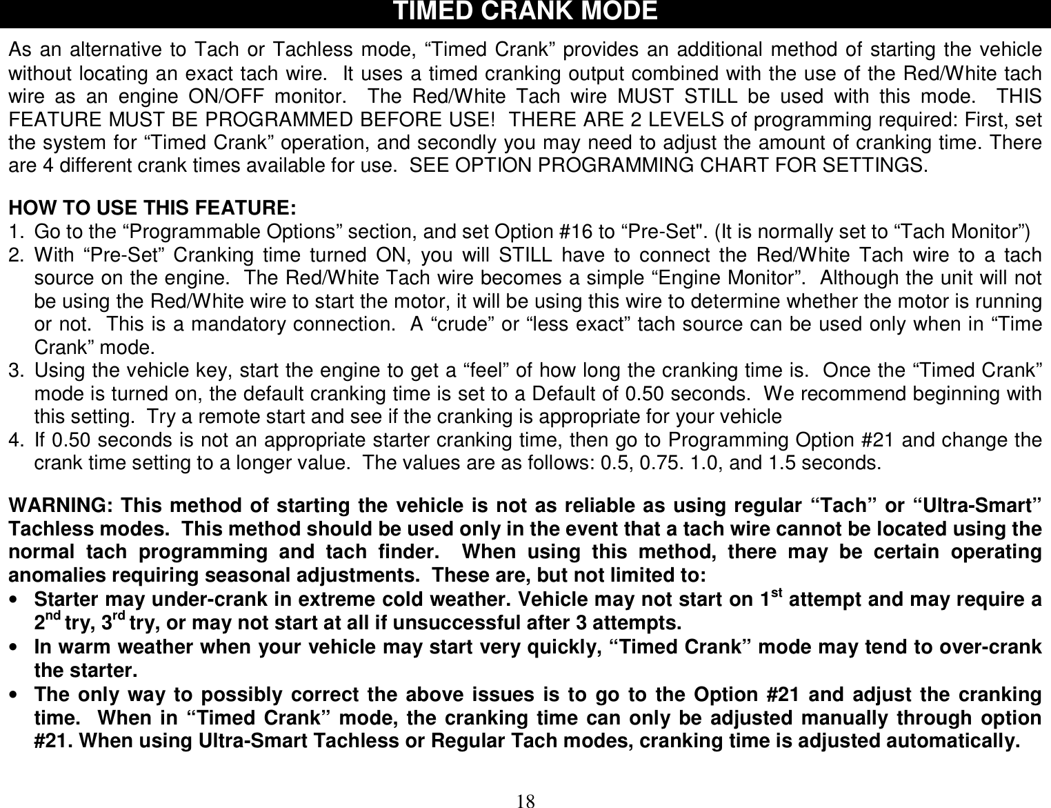
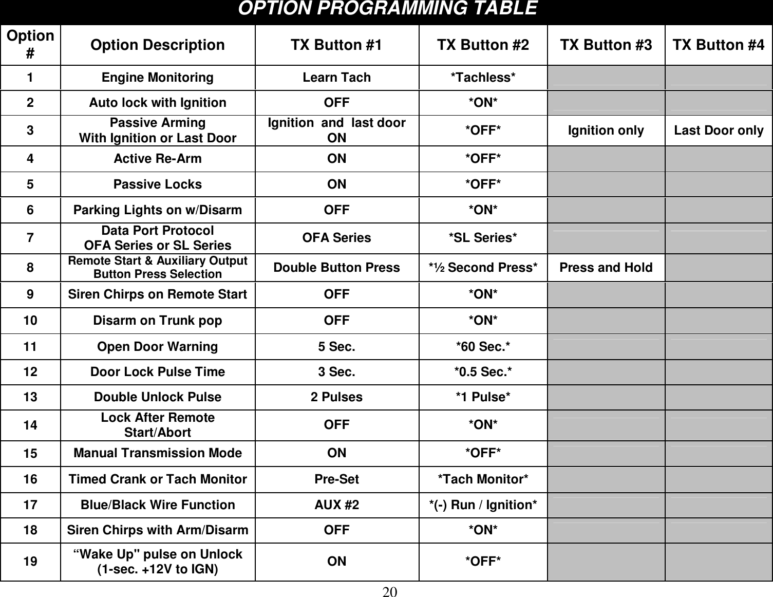
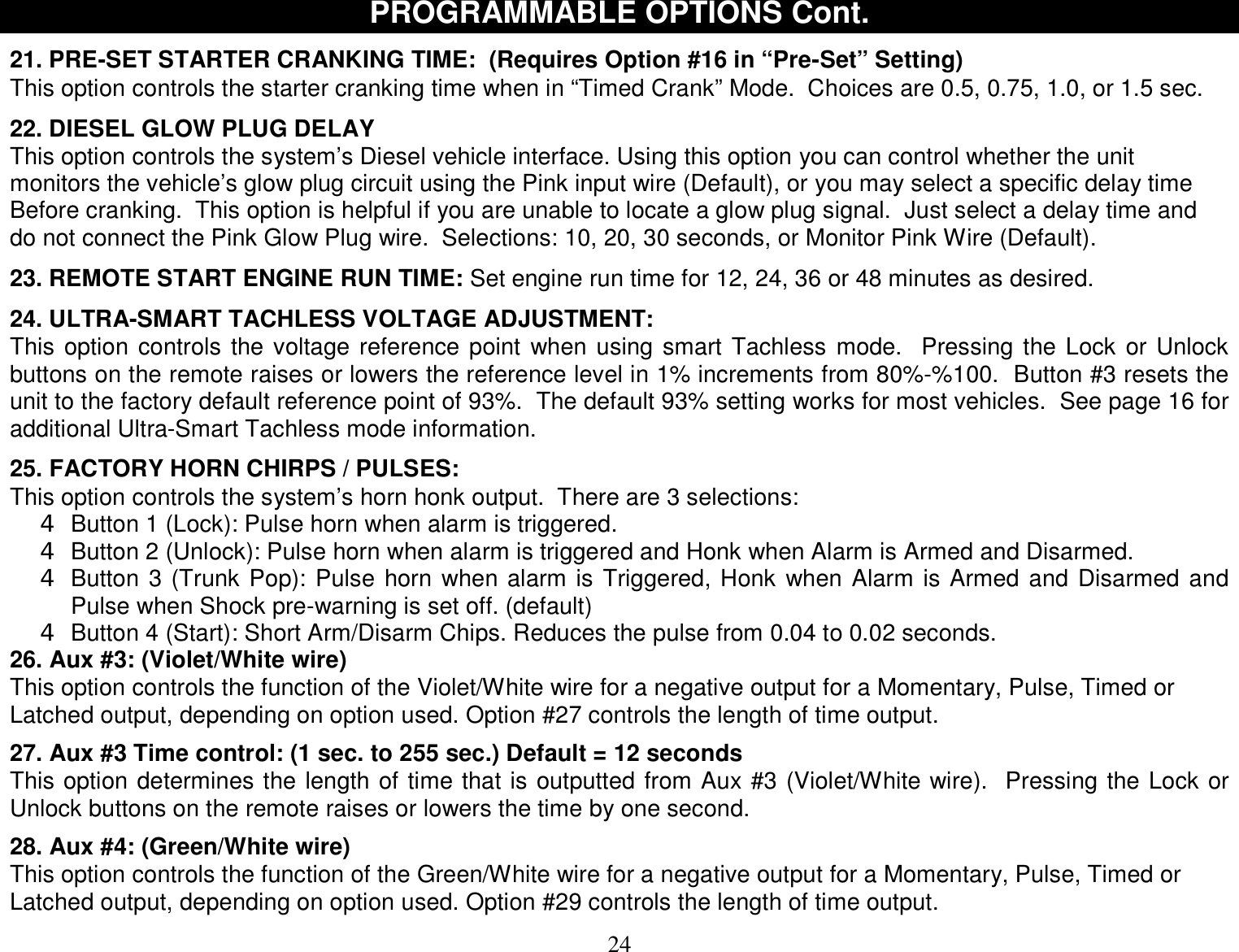
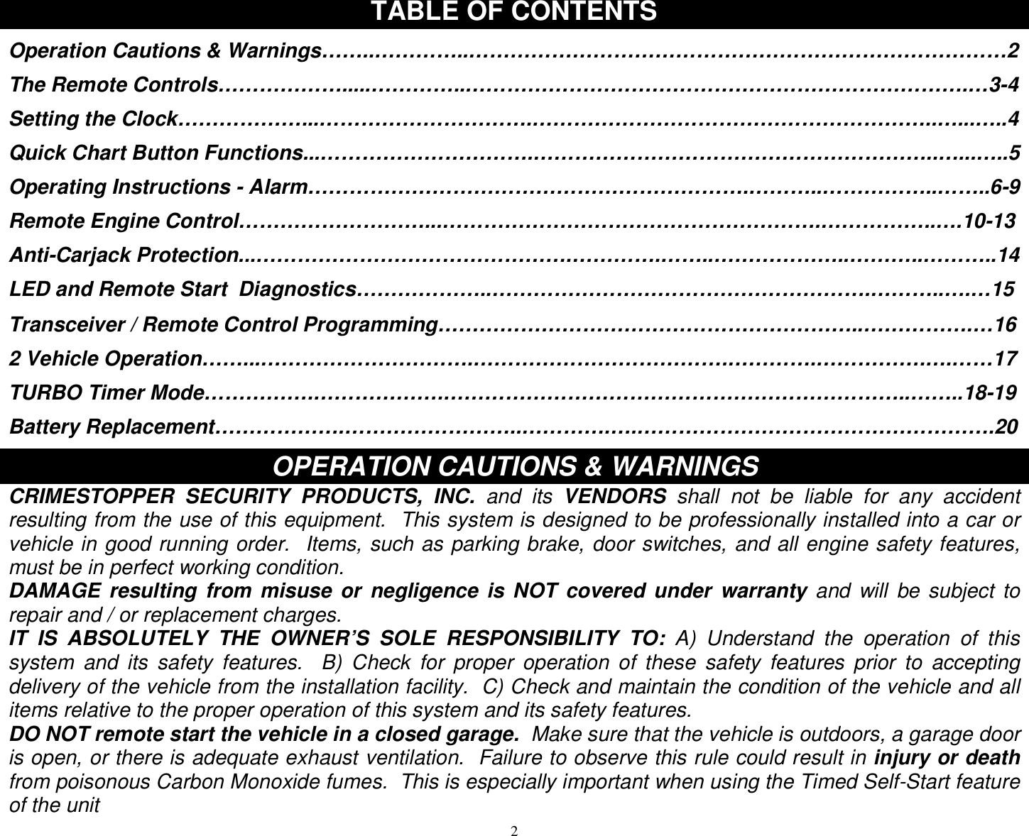
![16 TACHLESS MODE Your system includes a Tach-less mode that actively monitors and compares the vehicle’s resting voltage versus its running voltage each time a remote start is performed; [instead of the conventional tach-pulse method]. Smart Tachless mode adjusts automatically to maintain optimum efficiency over the life of the installation. IMPORTANT NOTES: (1) SETUP may be required for the Tachless Mode. If your vehicle has NOT been at rest for a period of time (Hot engine), then you must drain the surface charge from the battery. Unplug main power harness from system, turn HEADLIGHTS ON for 4 minutes to drain off excess surface charge on vehicle’s battery then reconnect. (2) On the rare occasion that Tachless mode does not operate satisfactorily, change the voltage reference level as described below, or use a different mode such as “Tach Reference” mode, or “Timed Crank” mode. TACHLESS ADJUSTMENT: In the event Tachless over-cranks or under-cranks your starter, the settings can be changed. The purpose of adjusting the “Smart Tachless” Mode is to raise or lower the voltage reference threshold from the 93% default point. Raising or lowering this 93% point should increase or decrease your cranking time respectively. You can adjust the range from 79% to 100% in one percent increments. Factory default setting [starting point] is in the middle at 93% which should work for most vehicles. If you feel you need to fine tune the Tachless mode, then follow the steps below to adjust its reference level. 1. Open hood (or ground the Blue hood pin wire if no hood pin is installed) 2. Turn the key to the ON position (do not start vehicle). 3. Press program button 5 times, after a few seconds the unit will flash the lights 5 times. 4. Carefully press the program button 24 times to get to option # 24. You must get a light flash after each press. If the lights didn’t flash, then the unit did not register your button press. Only count the light flash. 5. Press the Lock Button #1 on the remote to decrease by 1% (lights will flash 1X for each press); Press the Unlock Button #2 to increase by 1% (lights will flash 2X for each press); Press the Trunk Button #3 to reset to 93% (lights will flash 3X). The unit will stop providing light flashes when you reach the bottom (79%) or the top (100%) of the adjustment range. If you lost track, then just press Button #3 to reset back to 93% and begin again. 6. Turn Ignition OFF, Close hood (or un-ground the Blue wire) and check operation.](https://usermanual.wiki/STEELMATE/BT0001/User-Guide-1085249-Page-16.png)
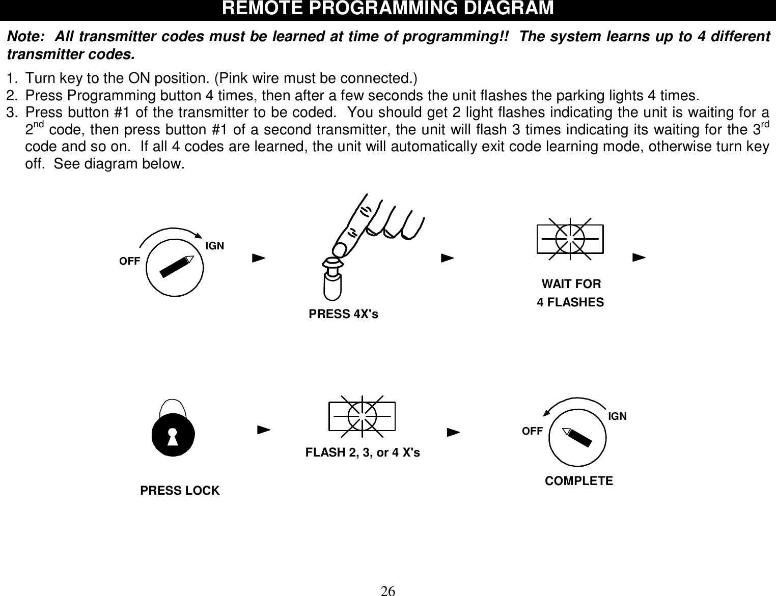
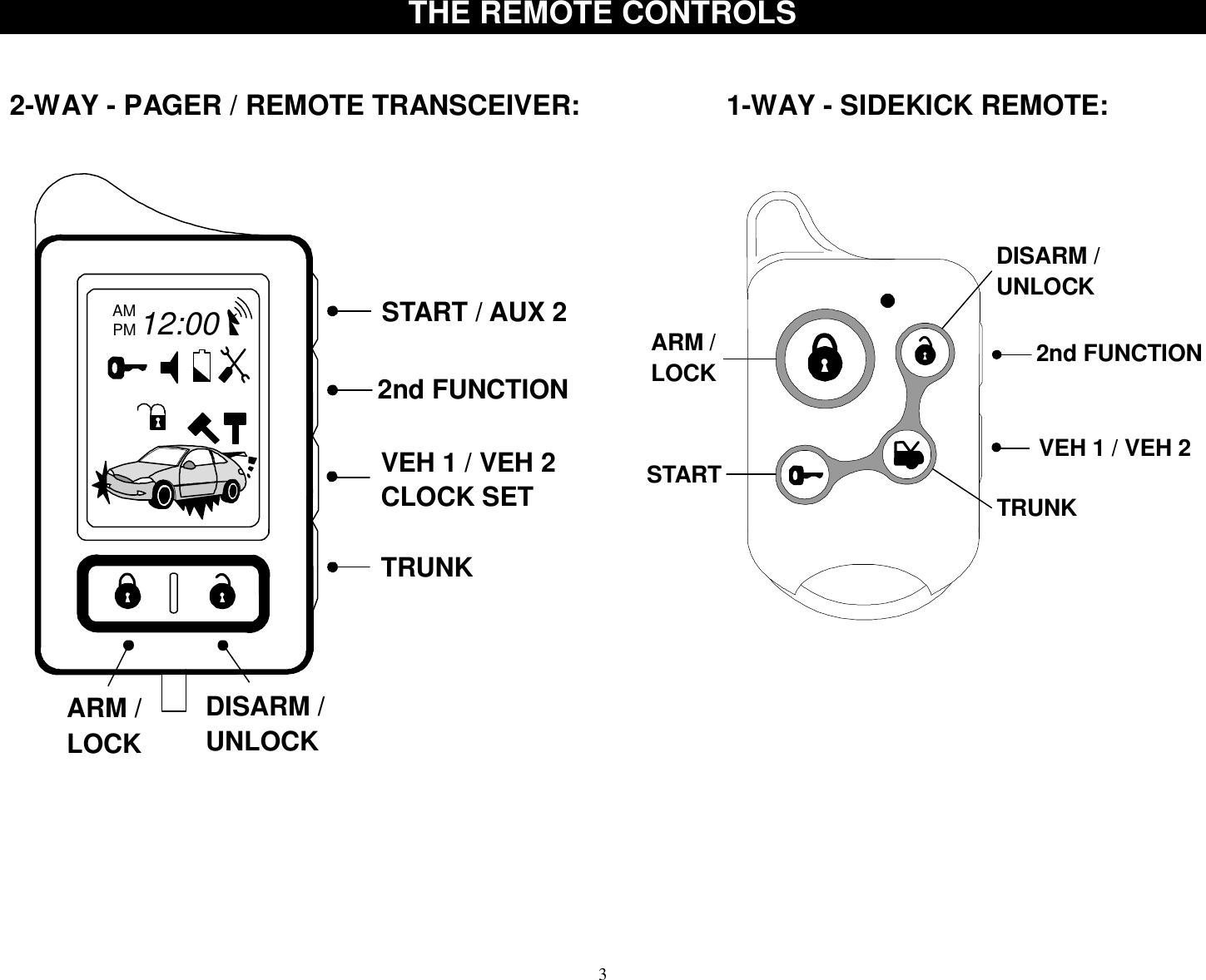
![17 TACH MODE & TACH FINDER FEATURE Tach Reference Mode provides reliable remote starting performance though engine speed sensing. When using Tach Reference Mode, the WHITE/RED wire is used for Tach signal [Engine RPM] input. Most modern engines include various points where the Engine Speed [Tach] or A/C signal may be obtained. Tach Signal examples: Negative (-) side of ignition coil, at the Distributor or Ignition Control Module, Coil Pack, Engine Computer, or Crankshaft Sensor. Sometimes Fuel injection solenoids and Alternator stator pins can be used. These Tach Signal locations mentioned are provided as a guide, your vehicle may differ. Some locations will NOT be a good location for Tach source due to RF noise or Computer Data. Use the TACH FINDER feature if needed. TACH FINDER FEATURE: The Tach Finder mode can assist you in locating or verifying a Tach source for your installation. Follow the Tach Finder steps below to locate signal. The unit will begin to flash the parking lights if you have the White/Red wire connected to a valid tach source. If lights do not flash, then try another wire until you locate a tach signal that will cause the Parking lights to flash. NOTE: On vehicles equipped with daytime running lights, it may be difficult to see any flashing parking lights. In this case your only notification will be the slight “ticking” sound coming out of the module from the on-board flashing light relay. TACH FINDER: 1. Open hood (Ground the Blue hood pin wire if no hood pin is installed) 2. Start Engine with the key. (Pink ignition wire must be connected) 3. Press the Program button for 2 seconds 4. Lights will begin flashing if the White/Red wire is connected to a valid tach 5. Once Tach is located then turn off engine and close hood to abort. 6. See Tach Reference programming below. TACH PROGRAMMING: 1. Open hood (Ground Blue hood pin wire if no hood pin is installed). 2. Connect WHITE/RED wire to a valid Tach source. 3. Start engine with the key (Pink ignition wire must be connected). 4. Press program button 5 times, then wait for 5 light flashes. 5. Wait at least one second then push program button again (1) time, you should get a light flash with the button press. This unit is now at option #1 for Tach Learning. 6. Press the #1 Lock Button on remote transmitter to program Tach. NOTE: Pressing the Brake Pedal also programs Tach. One Light Flash = Tach Mode. Two Light Flashes = Tachless Mode. 7. If lights do not flash for confirmation, then try another tach source or try the tach finder feature above.](https://usermanual.wiki/STEELMATE/BT0001/User-Guide-1085249-Page-17.png)
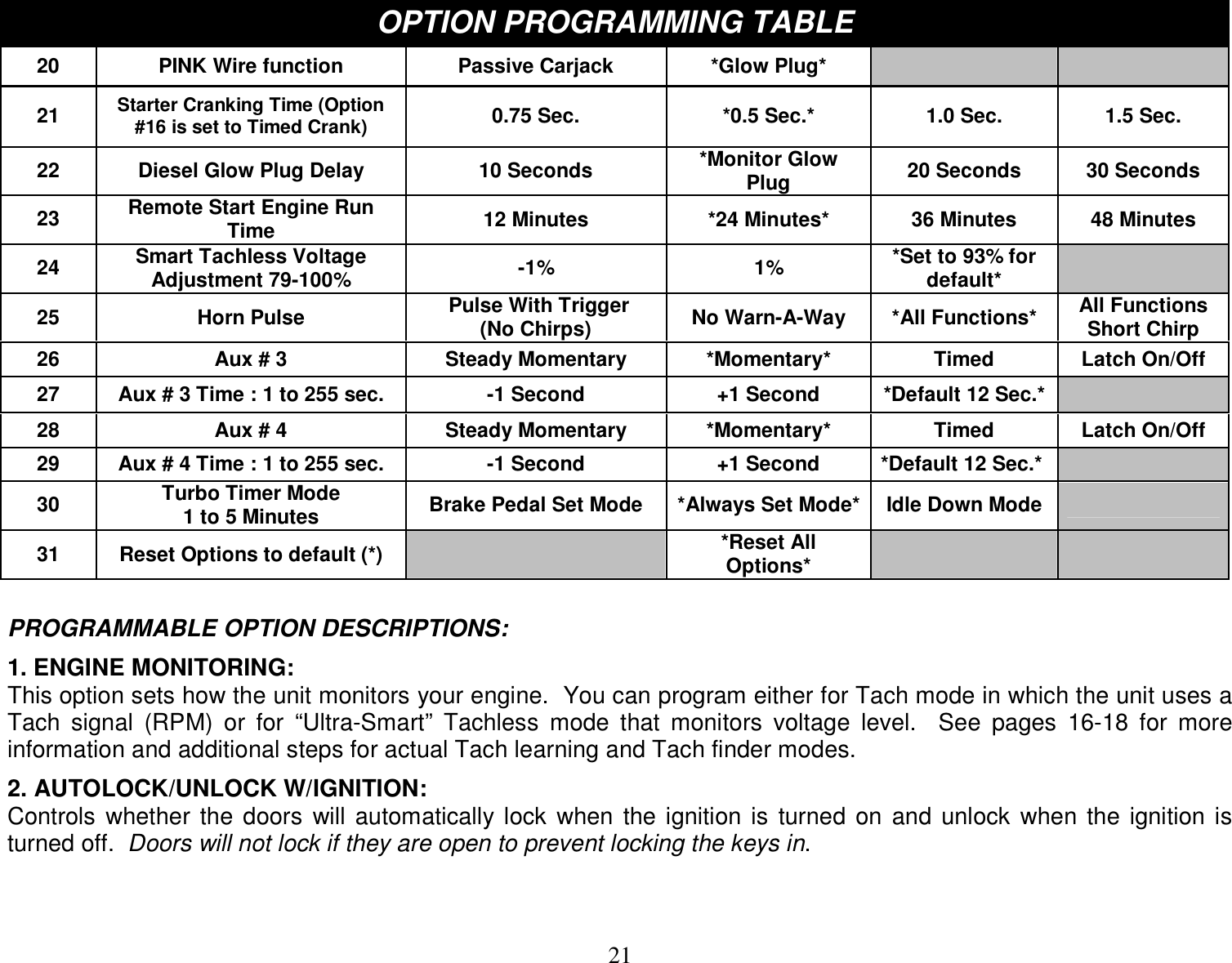
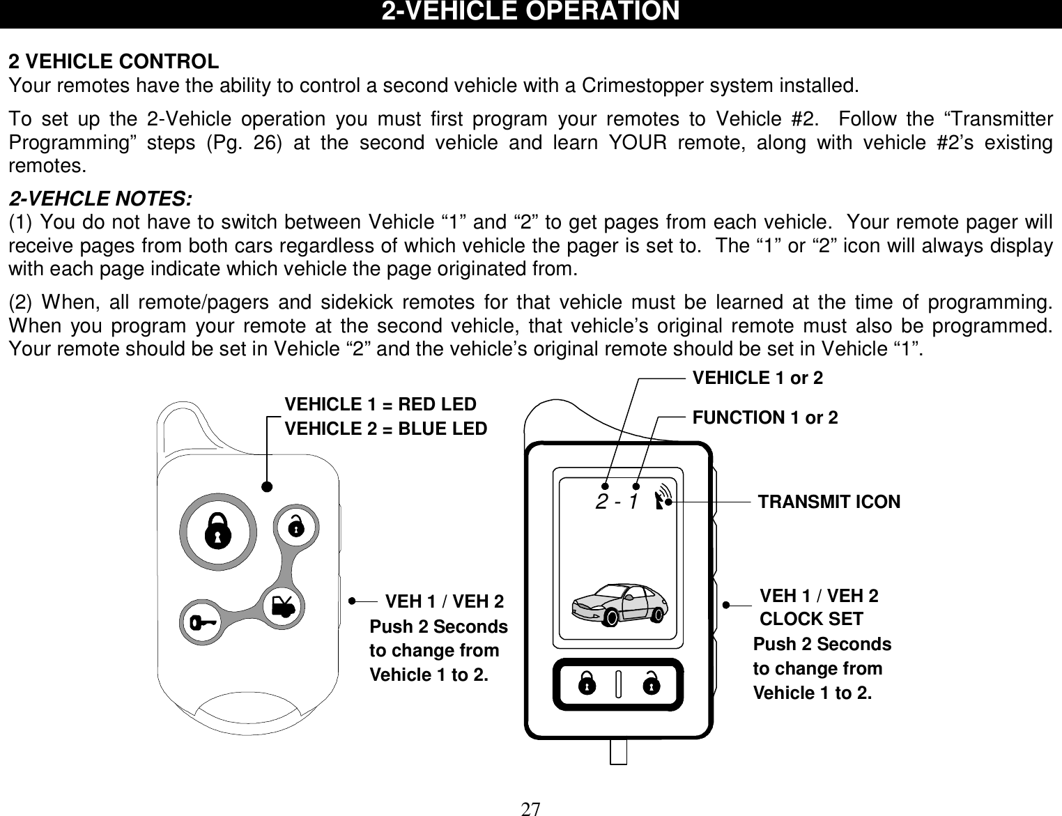
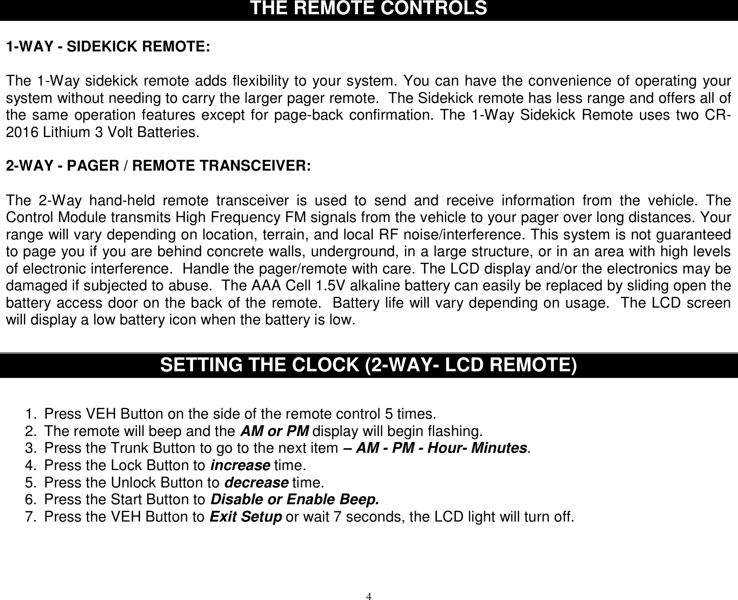
![19 DIESEL GLOW PLUG DELAY This feature provides a solution for diesel vehicles without having to connect to the Glow Plug-“Wait to Start Circuit” input. This may be due to a variety of reasons for example: If your vehicle does not have a viable “Wait to Start Circuit” or you cannot locate and identify the circuit. You can choose from a selection of “pre-cranking” delay times. Once this mode is activated, the system will NO LONGER monitor the PINK glow plug input wire and will use a delay setting chosen by the installer in the option chart. NOTES: This feature is OFF by default and must be programmed before use. Once this feature is turned ON, the Pink Glow plug input wire is not used. The Remote start unit will always wait the programmed time before cranking EVEN IF the glow plugs warm up first. There are 3 different Delay times available for use: 10, 20, or 30 seconds. SEE PROGRAMMING OPTION CHART, next section. HOW TO USE THIS FEATURE: 1. See the “Programmable Options” next section and change Option #22 from "Monitor Glow Plug Light" to one of the delayed time values. (Default setting is to always monitor the PINK Glow Plug input wire.) 2. Once this option has changed the system will wait for the selected time before cranking the engine. PROGRAMMABLE OPTIONS You can program multiple options in one session if you start with the lowest option and continue on to higher options [if needed] without repeating steps #1-3 below. For example, you can follow the programming steps to change Option #2 to “OFF” by pressing the lock button on the remote, then you can continue pressing the program button additional times to get to a high number option and change the setting without having to repeat Steps 1-5. You can only go from low to higher option numbers in one session. To Engage Option Programming: 1. Open Hood (ground blue hood pin wire if no hood pin switch is installed) 2. Turn Key to the ON position 3. Press program / valet button 5 times, after a few seconds the unit will flash the lights 5 times. 4. Push the valet/program button [again] the number of times that corresponds to the option number desired (1 thru 30). You must get a light flash after each button press. See chart on next page for option list. 5. When you reach the desired programming level, Press button #1, #2 #3 or #4 to change the option. 6. Turn Ignition OFF, Close hood (or unground blue hood pin wire) and check for changed features. Change each option individually repeating #1-5.](https://usermanual.wiki/STEELMATE/BT0001/User-Guide-1085249-Page-19.png)
![25 PROGRAMMABLE OPTIONS Cont. 29. Aux #4 Time control: (1 sec. to 255 sec.) Default = 12 seconds This option determines the length of time that is outputted from Aux #4 (Green/White wire). Pressing the Lock or Unlock buttons on the remote raises or lowers the time by one second. 30. Turbo Timer Mode: The optional Turbo Timer mode allows the CoolStart system to keep a Turbo or Turbo Diesel vehicle running for 1 to 5 minutes [selectively] after you remove the key and exit the vehicle. This is handy for turbo cool-down without the need for expensive turbo timers. This mode requires the use of an extra part called a momentary switch/button that is not included with the kit. There are (3) modes of operation for the Turbo Timer Mode. See operation manual. 31. Option Reset: RESTORE TO DEFAULT This option allows you to restore all programmable options to factory default values. Go to the option 31 and press the Unlock Button #2 on the remote. The lights flash 2 times and all values will be reset to factory original settings. Default values are marked with asterisks in the chart on pages 20 and 21. PROGRAMMABLE OPTION RESET This system provides a reset method to restore all options to FACTORY DEFAULT VALUES as listed in the “Button #2” column of the programmable option chart on pages 20-21. This can be helpful if you have lost track of the option settings on your system, or when you are moving the system from car to car and want a “clean slate”. 1. Open hood (ground the Blue wire if no hood pin is installed) 2. Turn Key to the ON position (Pink ignition wire must be connected) 3. Press program / valet button 5 times, after a few seconds the unit will flash the lights 5 times. 4. Push the valet/program button 31 times. Press carefully, do not lose count! You must get a light flash each time you press the button. If the unit didn’t flash the lights, then the system did not register your press. 5. Press button #2 (Unlock) to reset the options. (Lights should flash twice) 6. Turn Ignition OFF, Close hood (un-ground Blue wire). All features should be set at *DEFAULT values.](https://usermanual.wiki/STEELMATE/BT0001/User-Guide-1085249-Page-25.png)

![9OPERATING INSTRUCTIONS - ALARM Dome Light Illumination (Optional) This feature will turn on the vehicle’s dome light upon disarming for 30 seconds or until the key is inserted and turned on. This will provide illuminated entry to your vehicle in dimly lit areas for safety and security. Emergency Override (Disarm) If you have lost the transmitter or it stops working for any reason and the Alarm is armed, you will have to disarm the system manually. Open the door with the key [alarm will sound], turn the ignition on, and press the override/program button for about 5 seconds. The Alarm will disarm and allow you to use the vehicle until you can repair/replace the remote. Valet mode also prevents Passive Arming. Valet Mode (Enter manually or using the remote) To disable Alarm and Remote Engine Starting for vehicle servicing the alarm system must be disarmed. To Activate Valet Mode: Turn the ignition on and press the override/program button [about 5-6 seconds] until you hear (3) siren chirps and the LED turns on solid. Repeat the process to exit VALET mode. To enter / exit Valet via the remote, press and hold both the Lock and Unlock Button together for about 3 seconds until 3 chirps are heard. Repeat this step to exit via the remote transmitter. Lock / Unlock and AUX features will still operate in VALET Mode however, Remote Start and Alarm functions are inhibited. Valet Park Mode (Using the remote transmitter only) Valet Park Mode allows you to turn over the vehicle to a Valet allowing access to drive/lock/unlock your vehicle, but alarm will trigger if the trunk is opened. To Activate Valet Park: The alarm system must be disarmed. Press and hold both the Lock and Unlock buttons together for about 3 seconds, 3 chirps will be heard first when unit goes into regular Valet. Release, press and hold both buttons again, you will hear 2 more chirps. The LED will always flash slowly when in Valet Park even when the Ignition is turned on (or driving vehicle). Repeat step above to exit Valet Park Mode. Note: Valet Park mode is only accessible when using the remote transmitter](https://usermanual.wiki/STEELMATE/BT0001/User-Guide-1085249-Page-41.png)
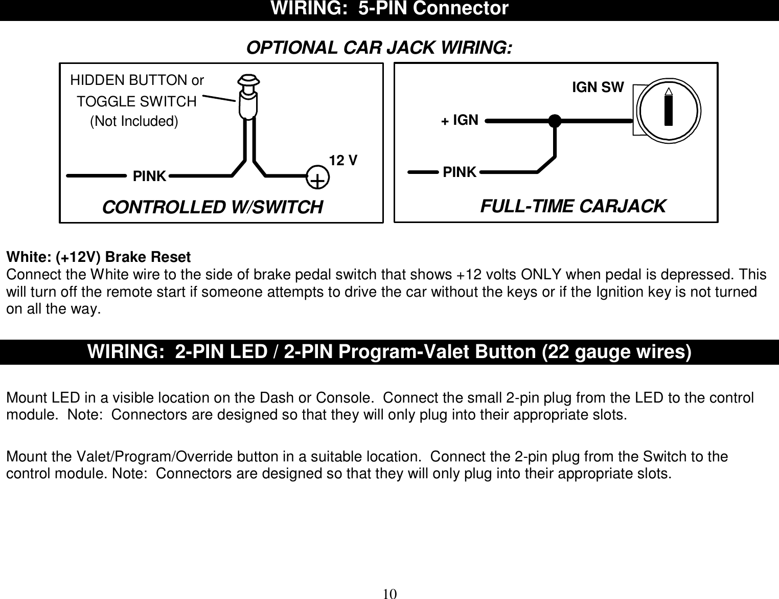
![14 ANTI CARJACK PROTECTION REMOTE OPERATED CARJACK PROTECTION This feature provides Active Carjack protection through the remote control. When the Ignition is on (vehicle is running), press and hold the #1 LOCK Button and #3 TRUNK Button for 2 seconds. The parking lights will flash 2 times and the LED will begin to flash rapidly to confirm the beginning of a Carjack countdown. 30 Seconds later, the unit will begin a Carjack Cycle consisting of 20 seconds of pre-warning chirps turning into a full system activation with siren / flashing light pulses for up to 5 min. If the Ignition is turned off during a Carjack trigger the siren and lights stop but Carjack protection is still active. The Siren and Lights will resume if the Carjacker tries to turn the Ignition back ON. TO RESET: Press Button #2 (UNLOCK) on the remote and the siren will chirp once, or turn the key on and press and hold the override button for at least 5 seconds. SWITCH-CONTROLLED & FULL TIME CARJACK (PINK WIRE CONFIGURATION) This feature can provide Passive or Manual control Carjack protection depending on the configuration of the Pink Carjack wire of the alarm system. The system must be programmed for the Pink wire to be used as a Carjack trigger with programming option #20. Once programmed for the Pink wire for use as a Carjack trigger, it can be configured in different ways to provide different levels of protection. It can be connected to a hidden +12V toggle/momentary switch or to +12V Ignition Power. Read following sections for further descriptions. HIDDEN SWITCH-CONTROLLED CARJACK: This configuration will enable the vehicle owner to activate a Carjack countdown by pressing a hidden push-button (not included with kit) during a Carjack situation. A Carjack countdown will begin under the following conditions: Ignition is ON (vehicle is running), the push-button is pressed, and the door opens/closes. Upon these 3 events, in that order, the alarm will start a Carjack countdown. After a delay of one minute, the system will begin chirping for 20 seconds then trigger into a full cycle for up to 5 minutes. To reset this Carjack mode, Ignition must be ON then press and hold the override/valet button for 5 seconds (until LED goes out.) FULL-TIME [Permanent] CARJACK: We recommend that this configuration only be used if a serious threat of Carjack exists during everyday situations. When the Ignition is on (vehicle is running), anytime a door is opened, the Carjack countdown sequence will be initiated. There will be 2 light flashes and the LED will change from solid to quick pulsing as confirmation of a countdown sequence. To reset FULL TIME Carjack, the Ignition has to be ON, then press and hold the override/program button 5 seconds until LED stops pulsing. The LED will be on SOLID when in this mode anytime the Ignition is ON (or while driving) as a reminder that Carjack is waiting for a door to open.](https://usermanual.wiki/STEELMATE/BT0001/User-Guide-1085249-Page-46.png)
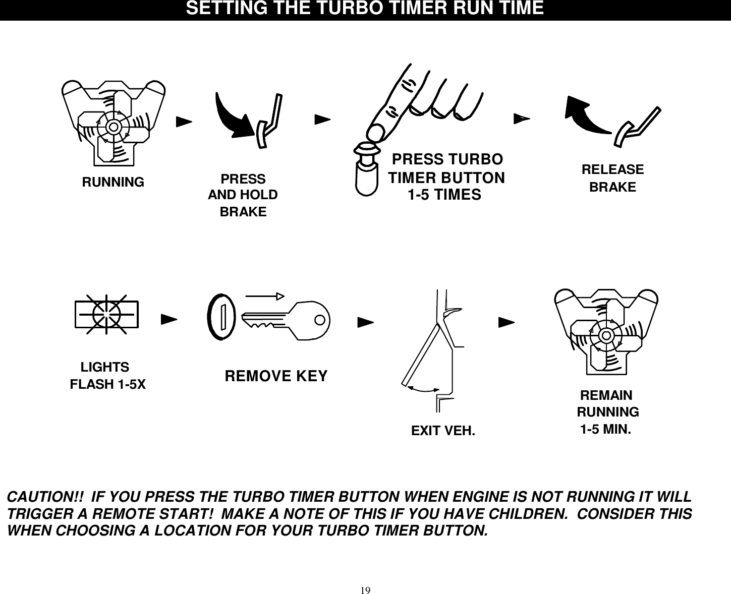
![18 OPTIONAL TURBO TIMER MODE The optional Turbo Timer mode allows the CoolStart system to keep a Turbo or Turbo Diesel vehicle running for 1 to 5 minutes [selectively] after you remove the key and exit the vehicle. This is handy for turbo cool-down without the need for expensive turbo timers. This mode requires the use of an extra part called a momentary switch/button that is not included with the kit. There are (3) modes of operation for the Turbo Timer Mode 1. Brake Pedal Set Mode. With the engine running by key, press Remote Start Button with brake pedal depressed. As you release the brake pedal, the Parking Lights and Status LED will blink the number of minutes for the Turbo Timer setting. The doors unlock after confirmation. The run time can be changed by using the push button switch attached to the green start activation wire (see Always Set Mode). 2. Always Set Mode (default). The Turbo Timer Run Time must always be set. With brake pedal depressed and engine running by key, Press the “Turbo Timer” button 1 to 5 times for each minute of run time you desire. (1 press = 1 min.) As you release the brake pedal, your system will confirm by flashing the lights the same number of times the button was pressed. The doors unlock after confirmation. Turn Ignition switch OFF, remove key and exit the vehicle. 3. Idle Down Mode. This replaces the normal Idle Down Mode. Can’t use Infinity Run or Manual Transmission Mode with this option. With the engine running by key, press the Remote Start Button. The Parking Lights and Status LED will blink the number of minutes for the Turbo Timer setting. The doors unlock after confirmation. The run time can be changed by using the push button switch attached to the green start activation wire (see Always Set Mode). Note: Mode 1 and 3, the run timer (1 to 5 min.) is set one time. The system always remembers the Turbo Timer setting even with battery disconnection.](https://usermanual.wiki/STEELMATE/BT0001/User-Guide-1085249-Page-50.png)