STEELMATE BT039001 Antenna User Manual DS1 7 ins rev 08 15 2012
STEELMATE CO., LTD. Antenna DS1 7 ins rev 08 15 2012
UserManual.wiki
>
STEELMATE
>
BT039001 User Manual
Users Manual
Navigation menu
Upload a User Manual
Namespaces
Wiki Guide
HTML
PDF
Info
Views
User Manual
Discussion / Help
Navigation
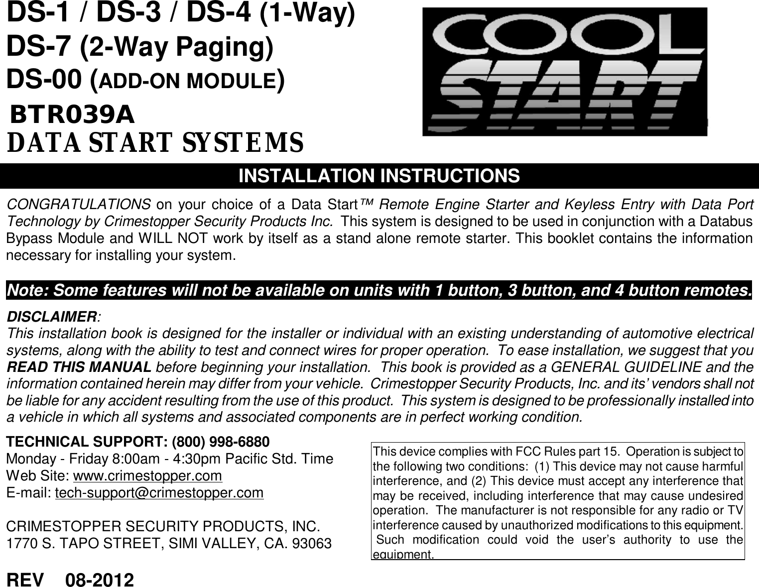
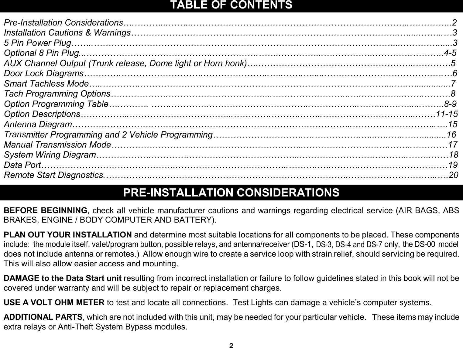
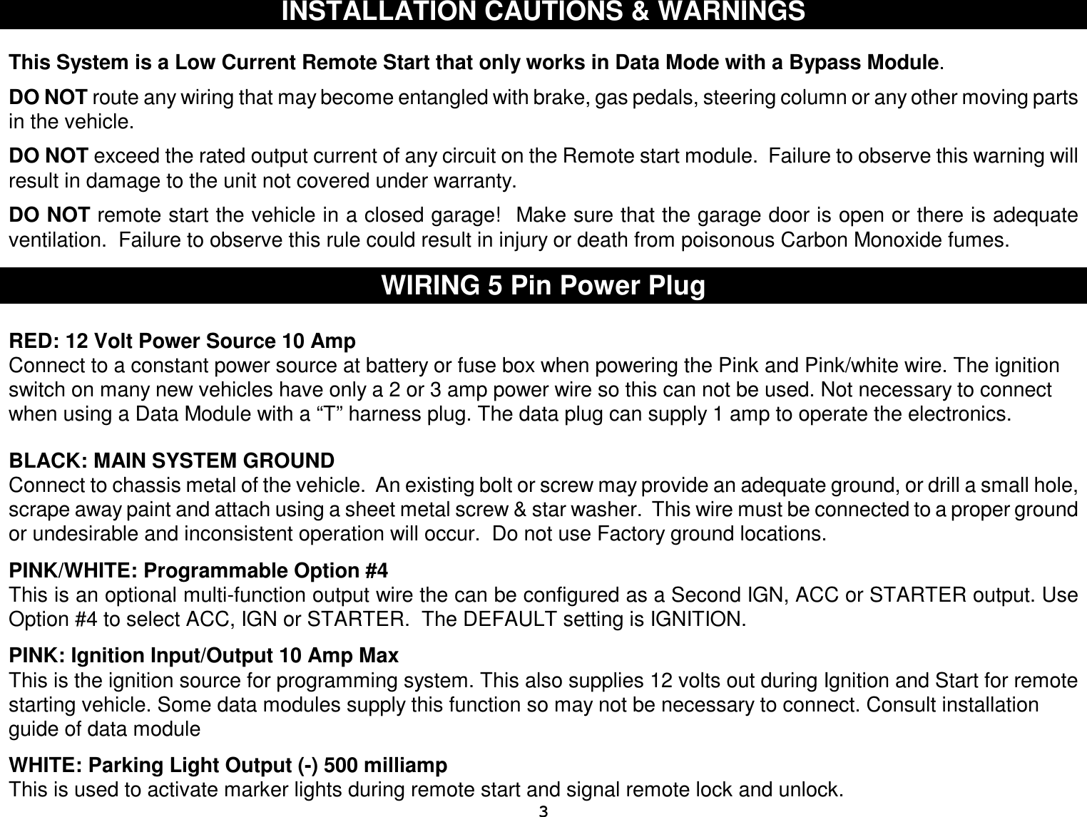
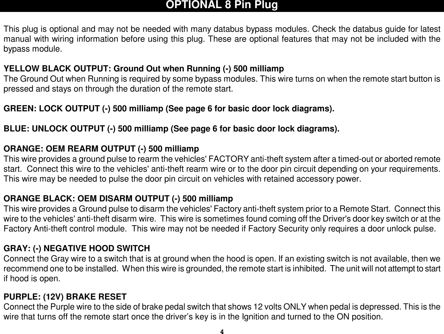
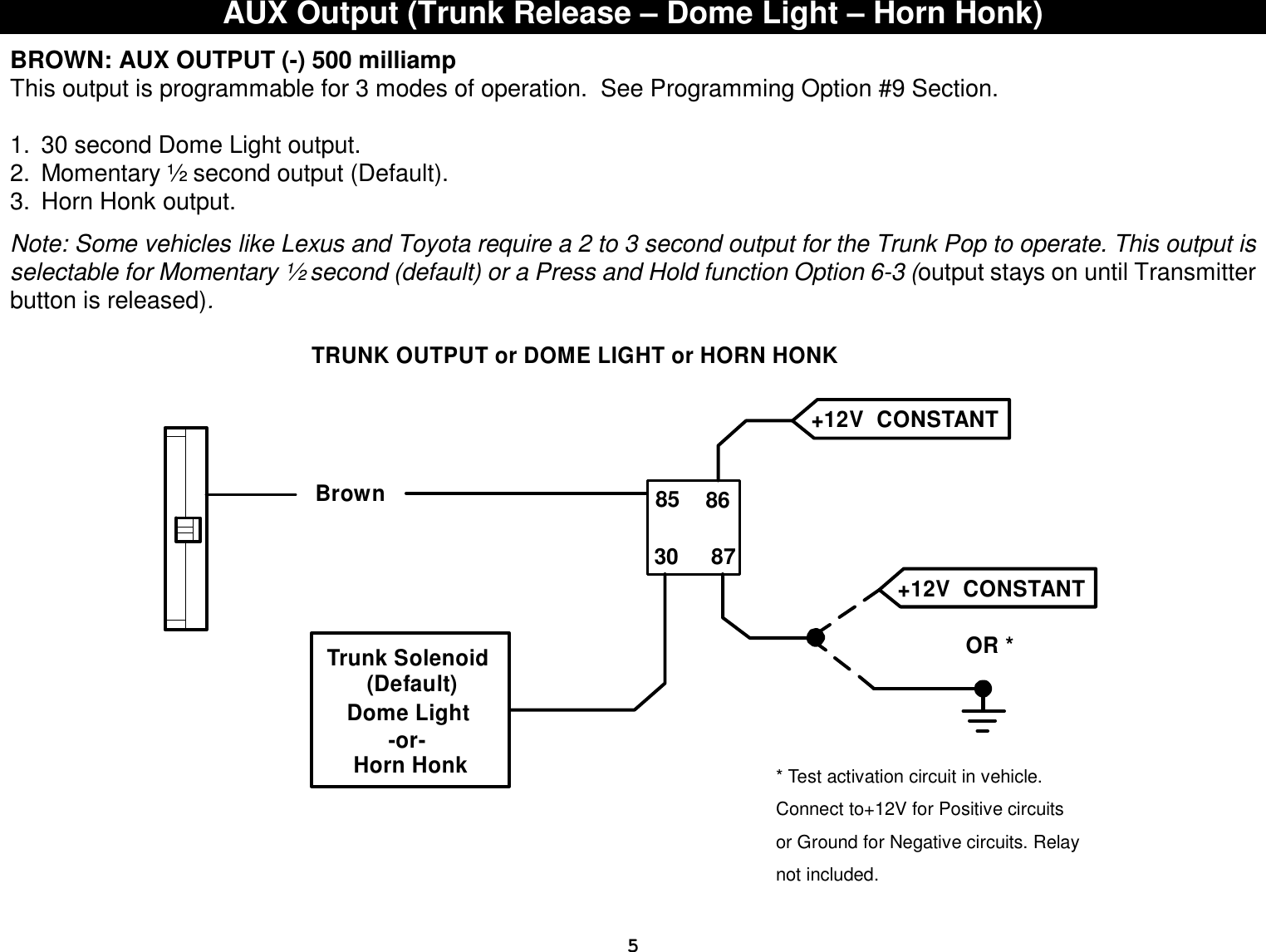
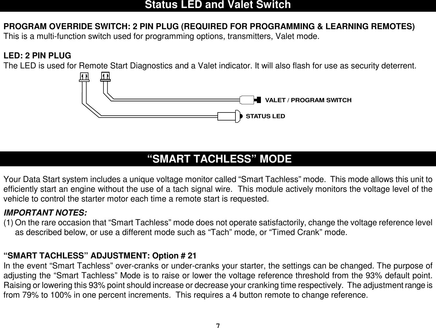
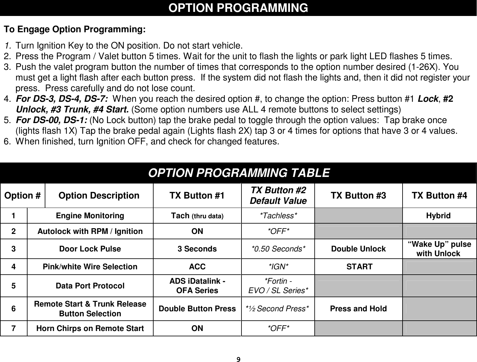
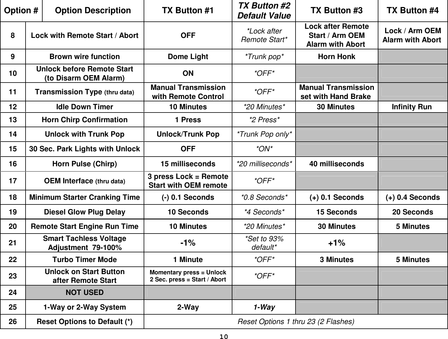
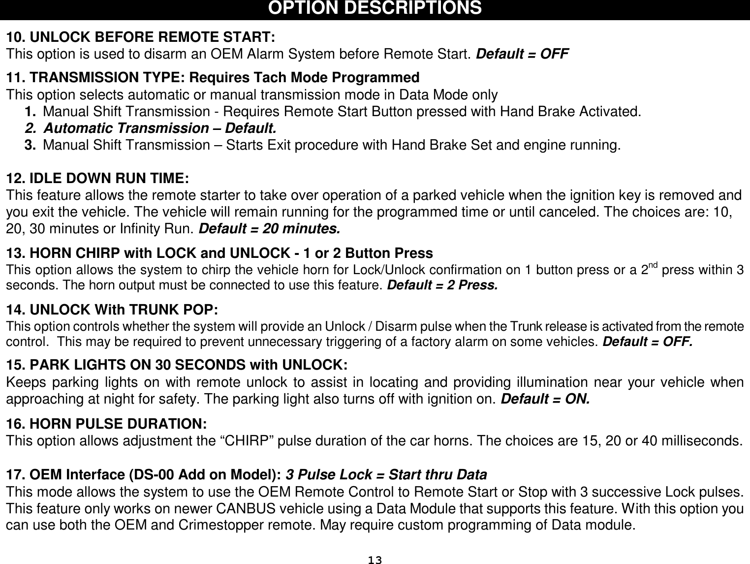
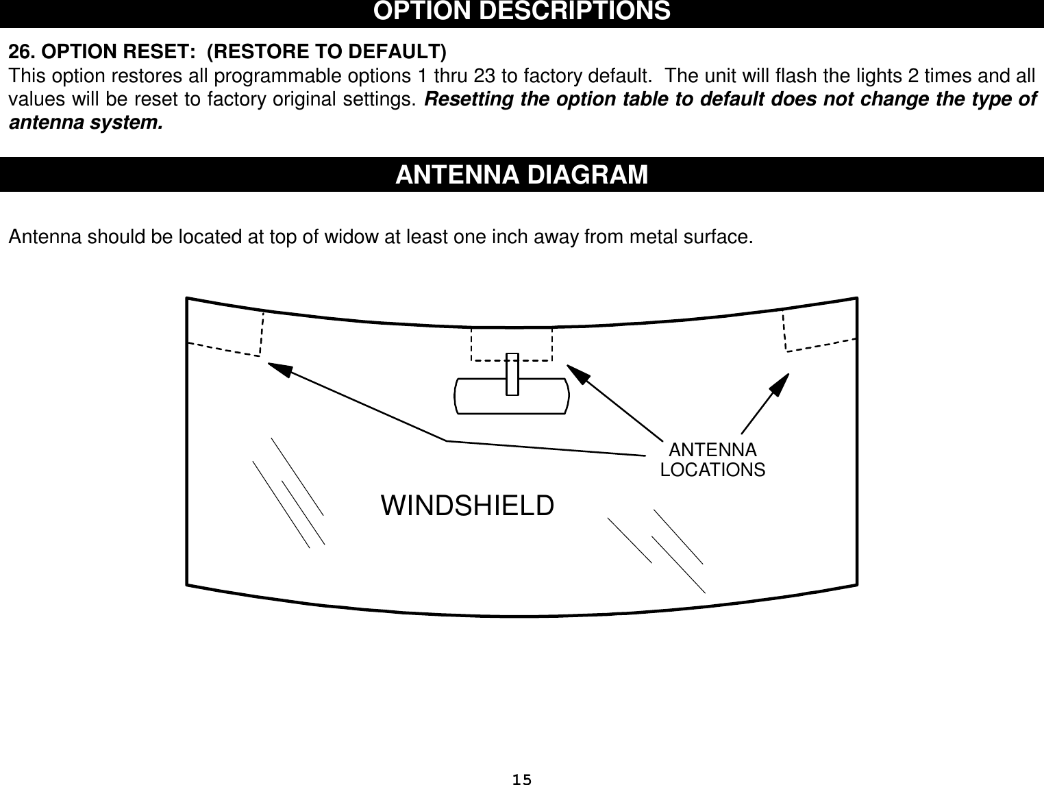
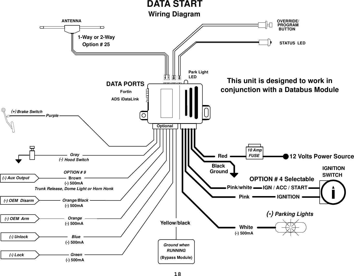
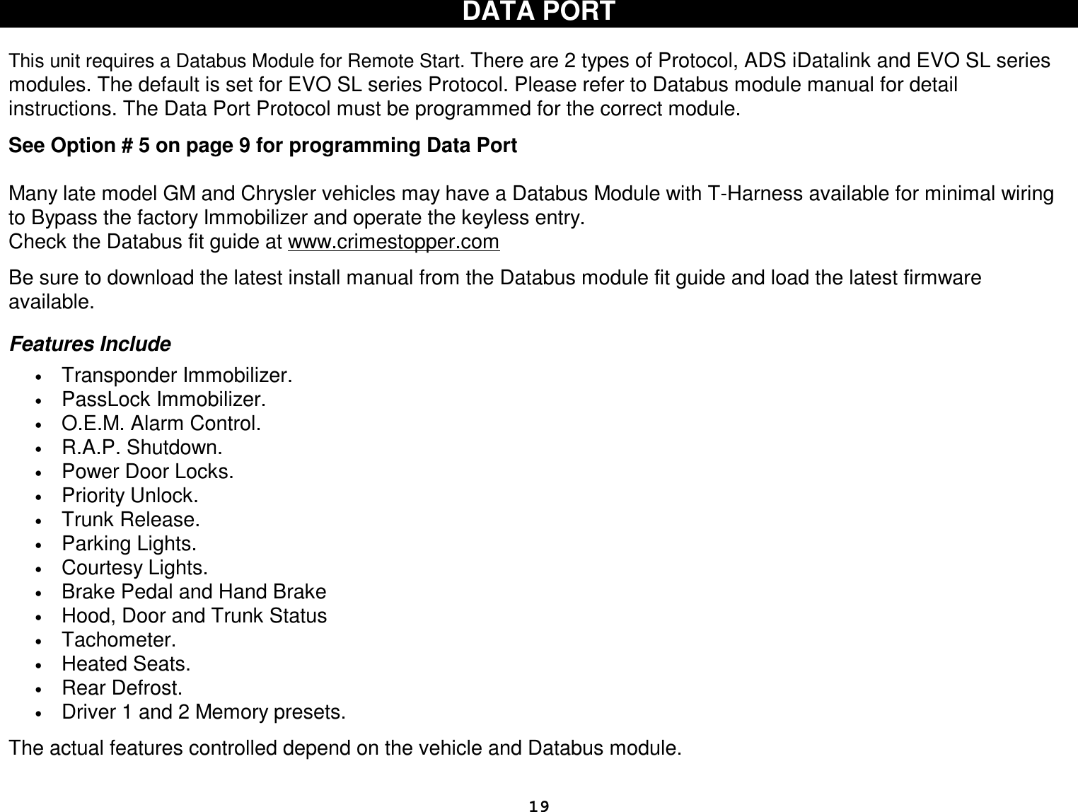
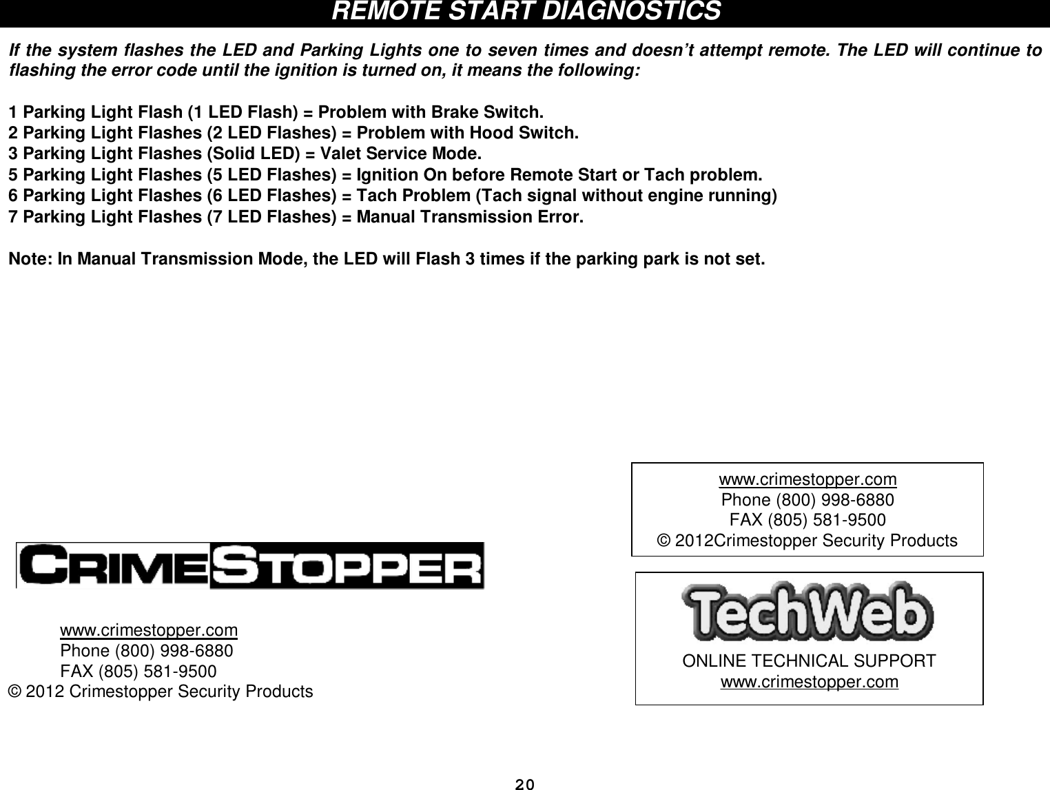
![14 OPTION DESCRIPTIONS 18. MINIMUN STARTER CRANK TIME: Default = 0.8 seconds This option controls the Minimum Starter Cranking time. This does not affect maximum crank time. This can be adjusted in 0.1 second increments Up or Down from 0.5 to 4 seconds. The starter can still crank up to 4 seconds with a 0.8 setting, depending on Tach or Tachless setting. TIMED START, use Hybrid Mode (option 1-4) with this option to set a fixed crank time. Please Note: In Hybrid Mode there is only 1 start attempt and the ignition is left on. 19. DIESEL GLOW PLUG DELAY: This option controls the system’s Diesel vehicle interface. Using this option you can select a specific delay time before cranking. Selections: 4, 10, 15 or 20 seconds. Default = 4 Seconds 20. REMOTE START ENGINE RUN TIME: Set engine run time for 10, 20, 30 or 5 minutes as desired. 21. SMART TACHLESS VOLTAGE ADJUSTMENT: This option controls the voltage reference point when using smart Tachless mode. Pressing the Lock or Trunk buttons on the remote raises or lowers the reference level in 1% increments from 79%-100%. Button #2 (unlock) resets the unit to the factory default reference point of 93%. The default 93% setting works for most vehicles. 22. TURBO TIMER: Using Remote Start Button The optional Turbo Timer mode allows the Data Start system to keep a Turbo or Turbo Diesel vehicle running for 1, 3 or 5 minutes [selectively] after you remove the key and exit the vehicle. This is handy for turbo cool-down without the need for expensive turbo timers. The Default = OFF. 23. UNLOCK ON START BUTTON: While remote started, this option allows the remote start button to unlock the doors with a ½ second press. 24. NOT USED 25. 1-WAY or 2-WAY SYSTEM: This selects 1-Way or 2-Way antenna system. The 1-Way system uses AM transmission. The 2-Way system uses FM transmission. The RF range will be much improved using the FM 2-Way antenna system. You must select this option using the brake pedal or remote control. If you accidentally change system from 1-Way to 2-Way (or vise versa), you need to use the brake pedal to change option 25 back to correct antenna system.](https://usermanual.wiki/STEELMATE/BT039001/User-Guide-1857468-Page-14.png)