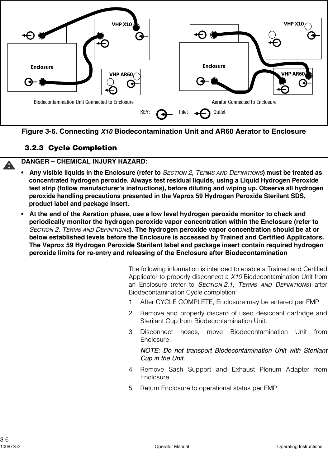
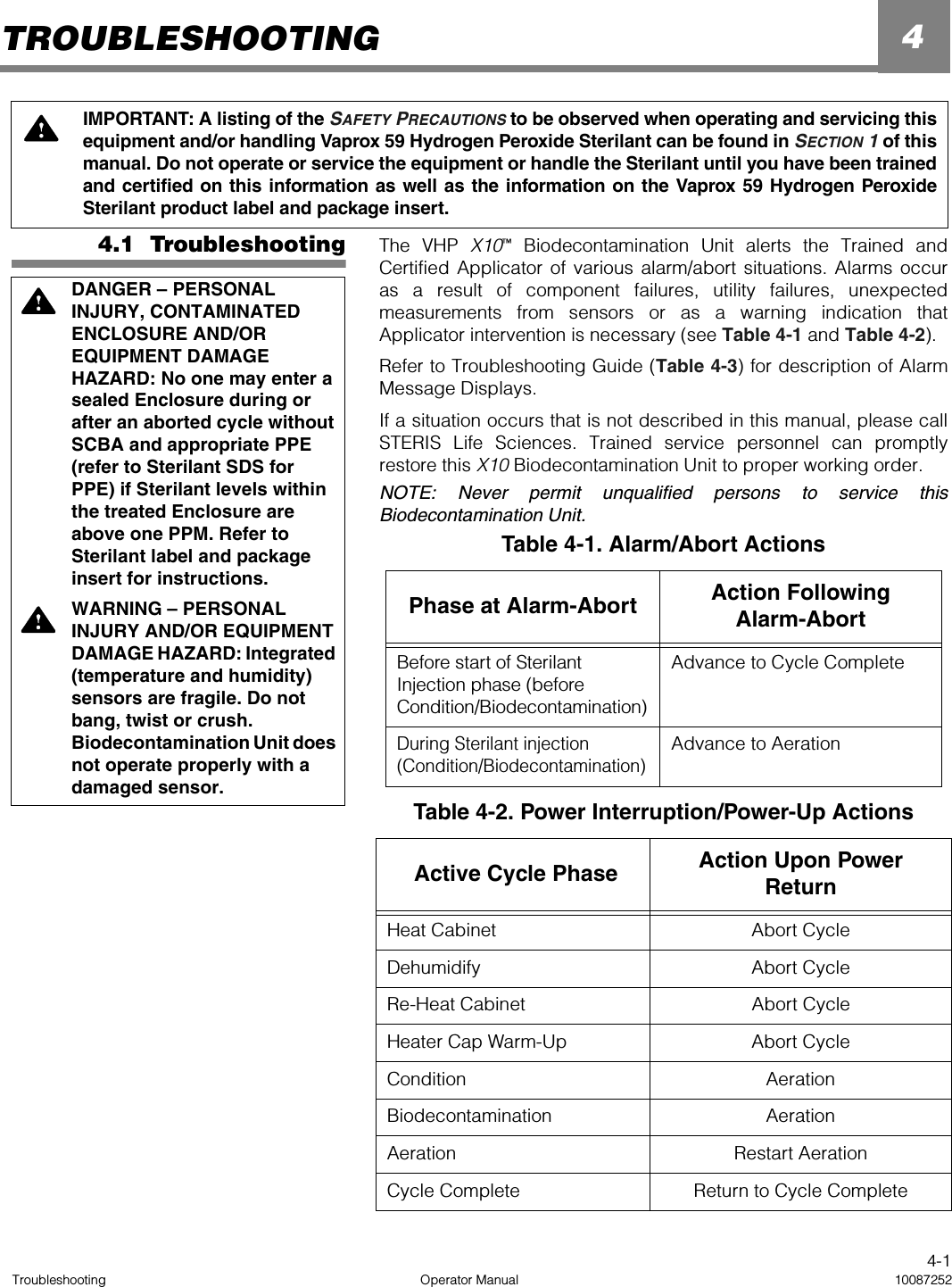
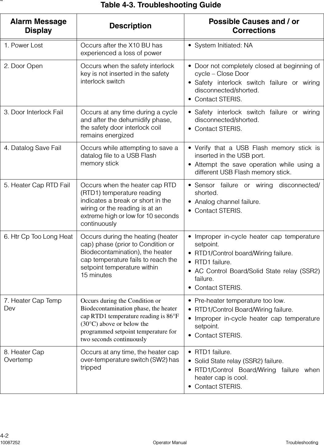
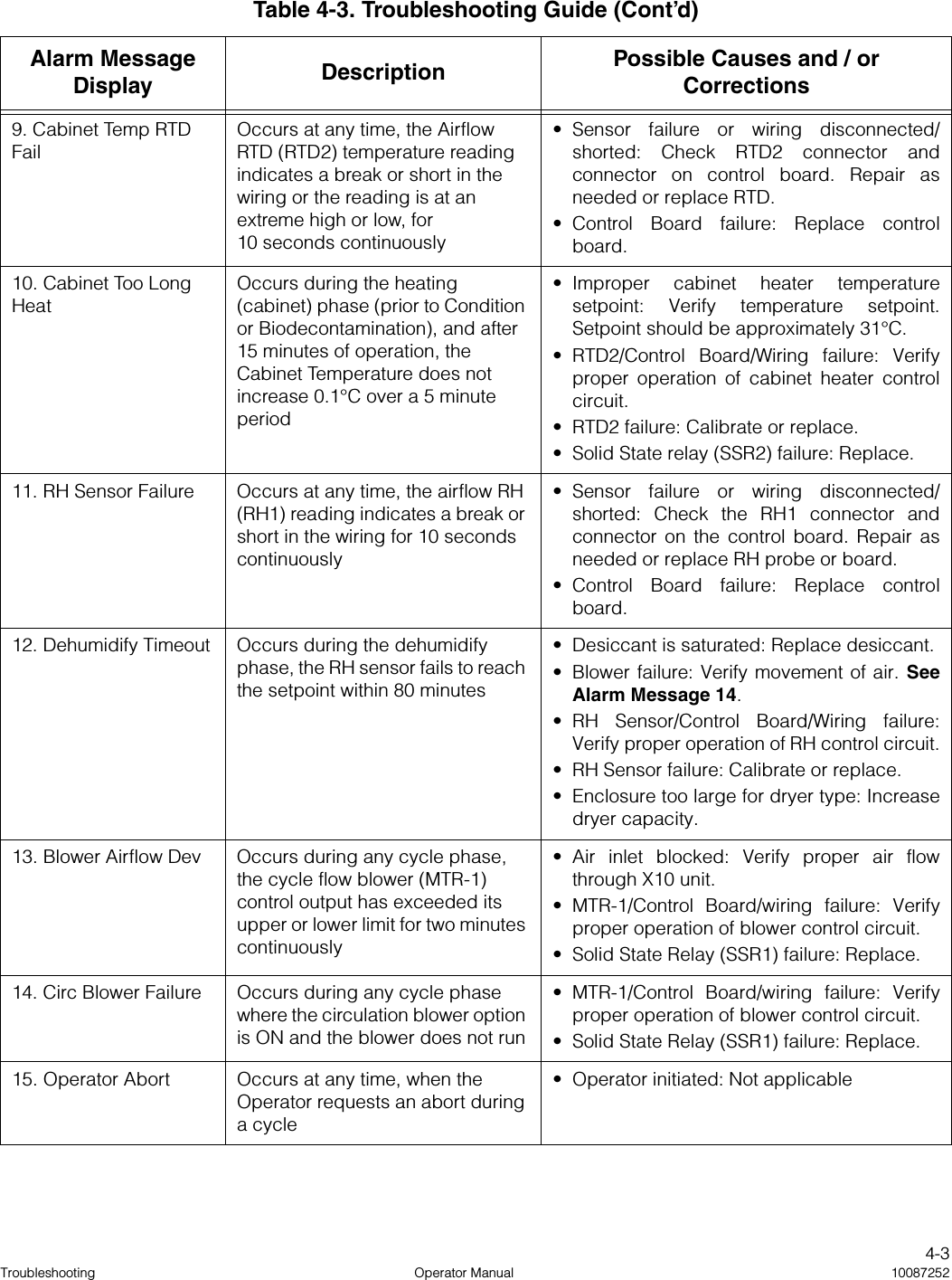
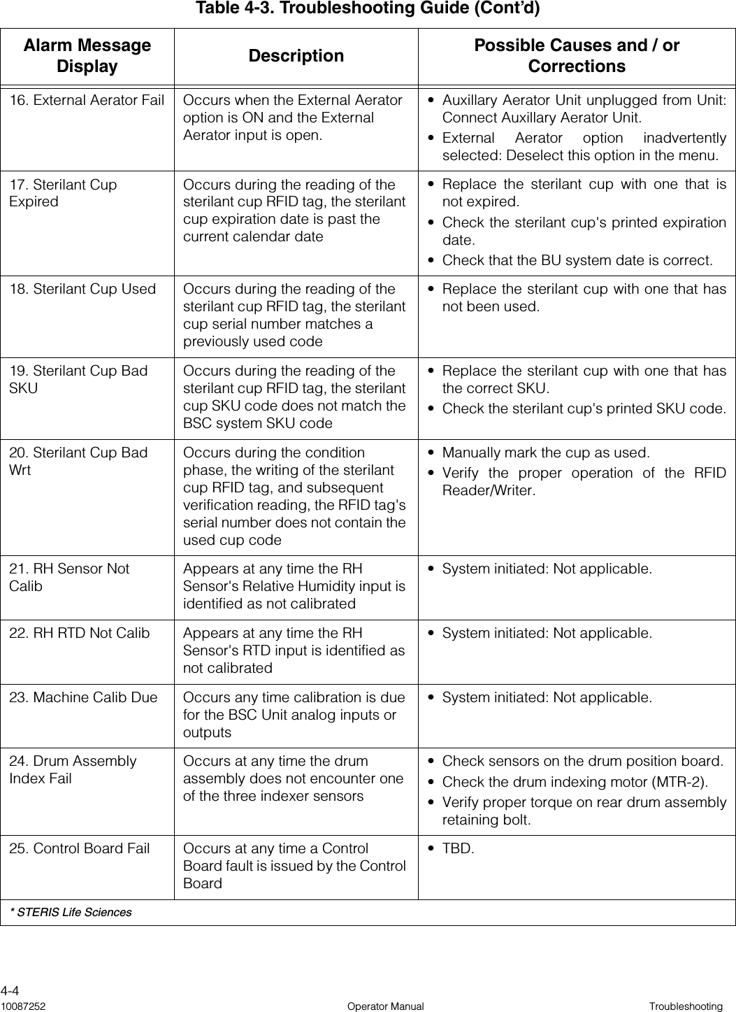
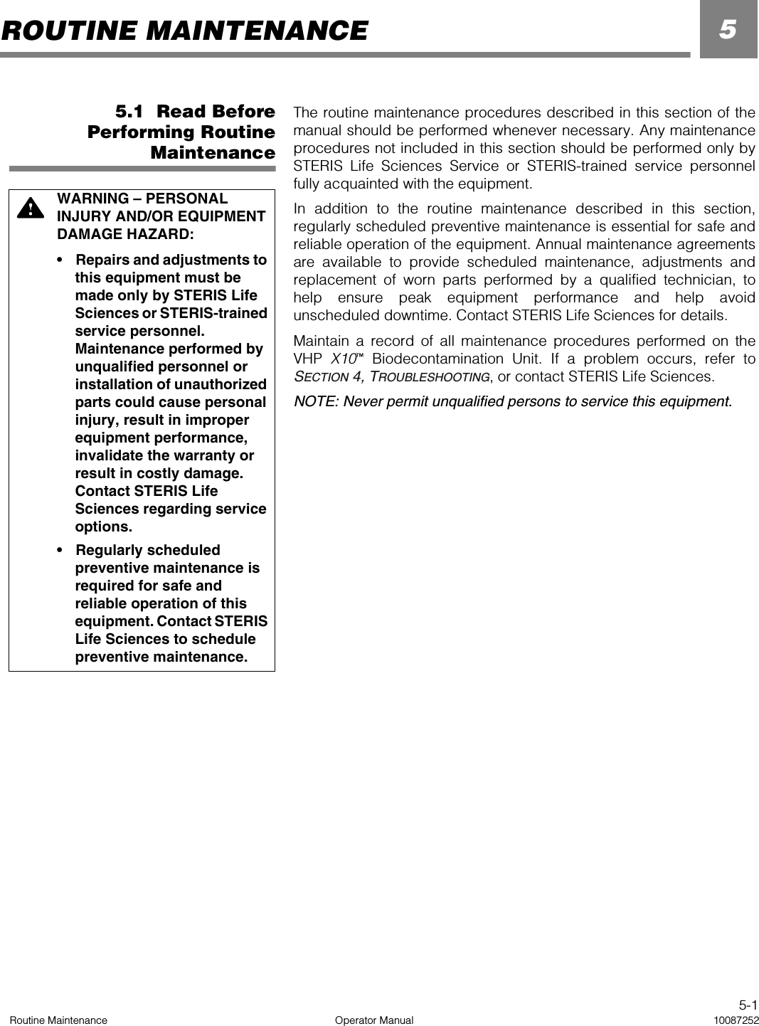
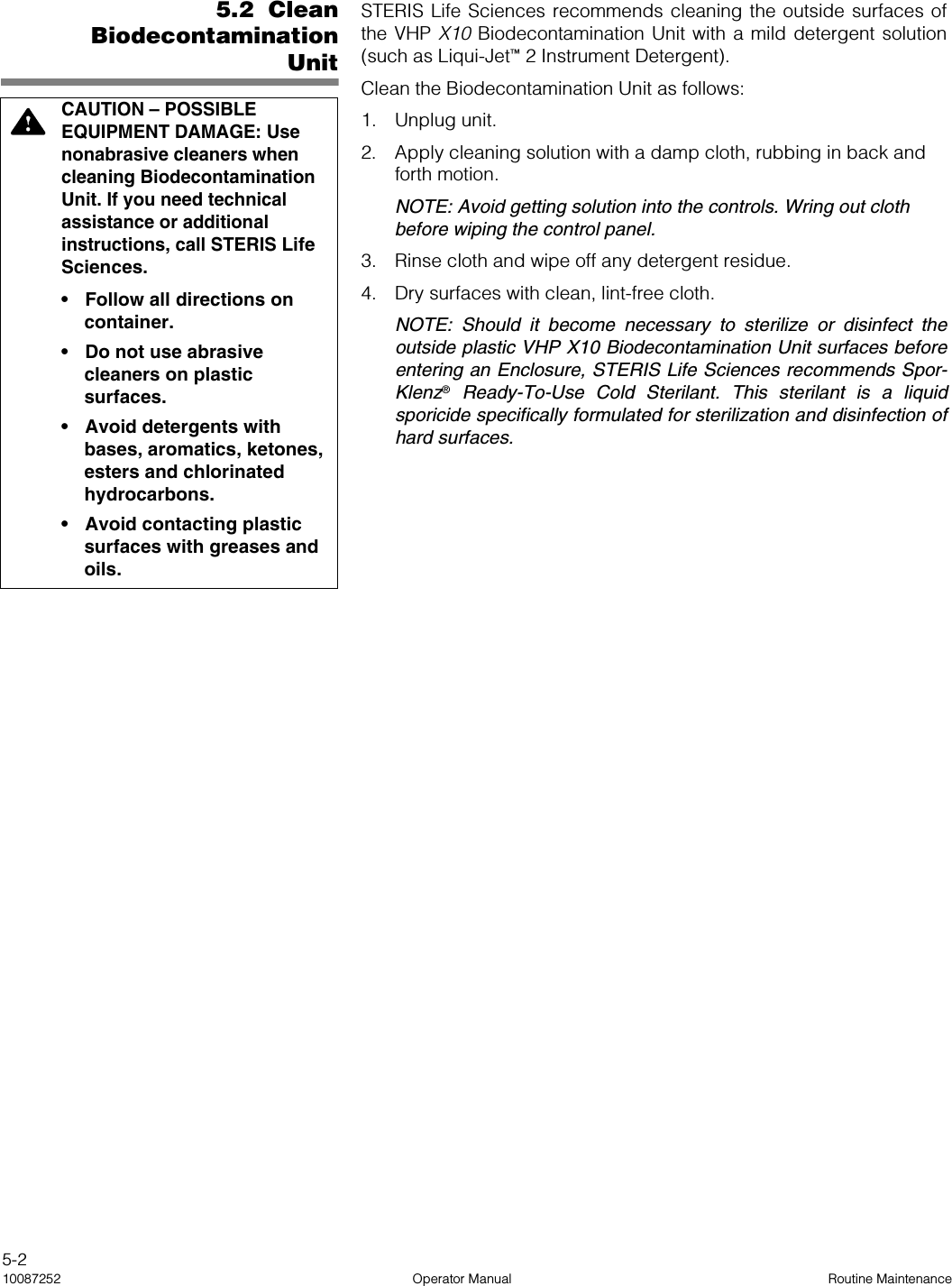
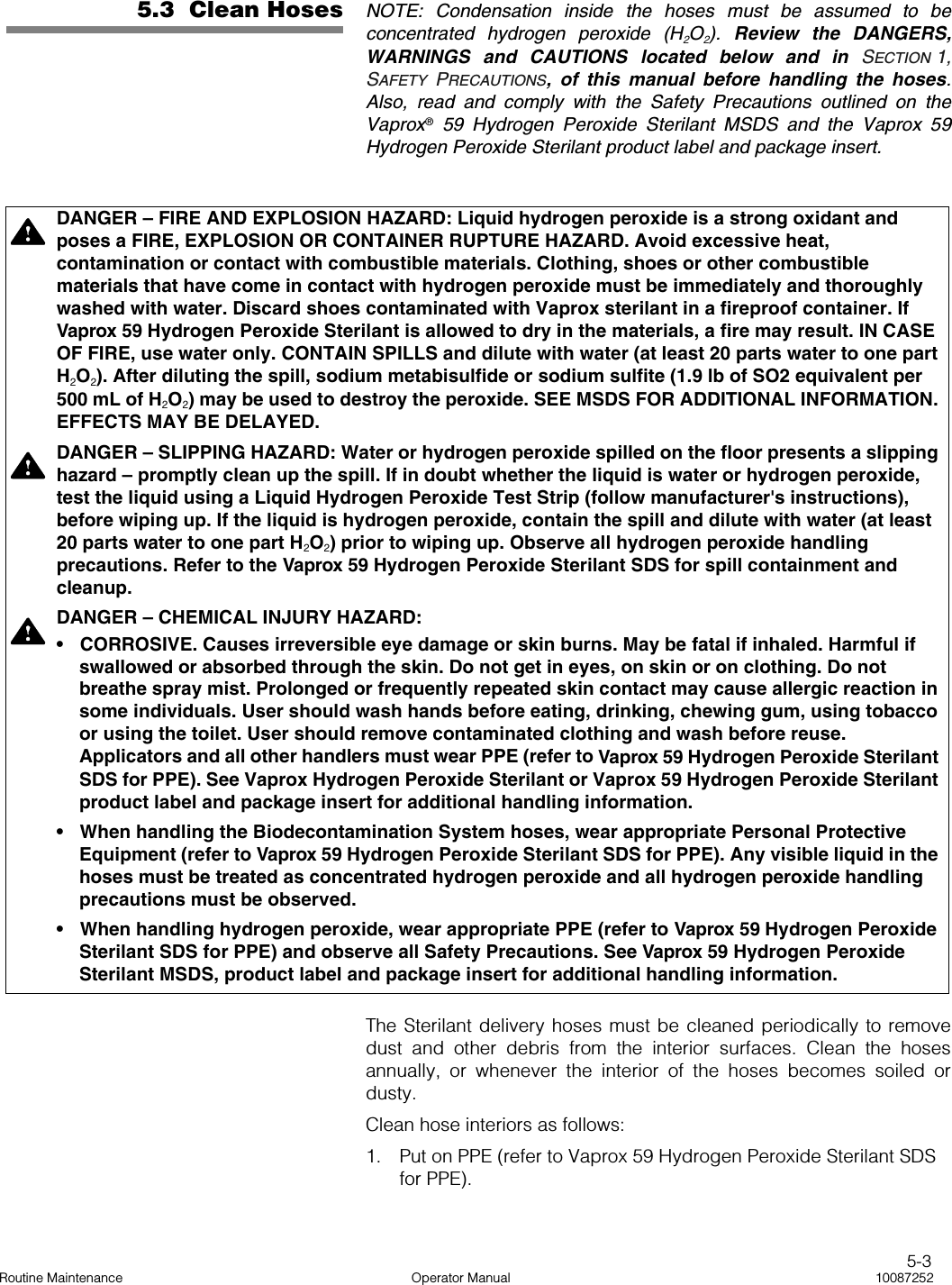
STERIS VHPX10 VHP X10 Biodecontamination Unit User Manual 10087252
STERIS Corporation VHP X10 Biodecontamination Unit 10087252
UserManual.wiki
>
STERIS
>
VHPX10 User Manual
>
Users Manual
Contents
1.
Users Manual
2.
Updated manual pages
Users Manual
Navigation menu
Upload a User Manual
Namespaces
Wiki Guide
HTML
PDF
Info
Views
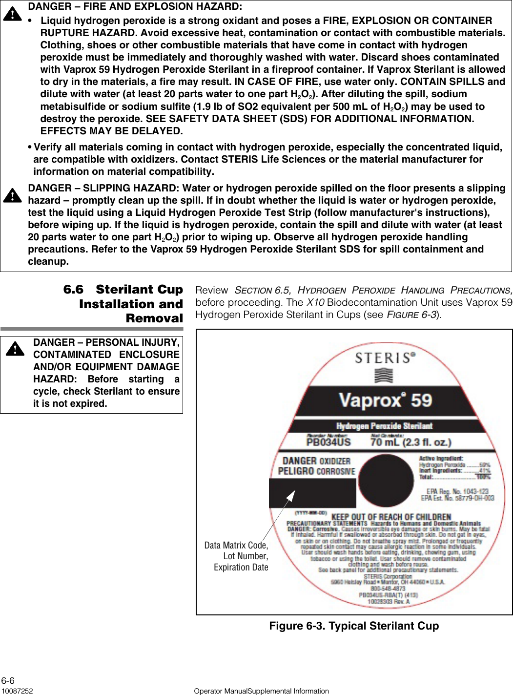
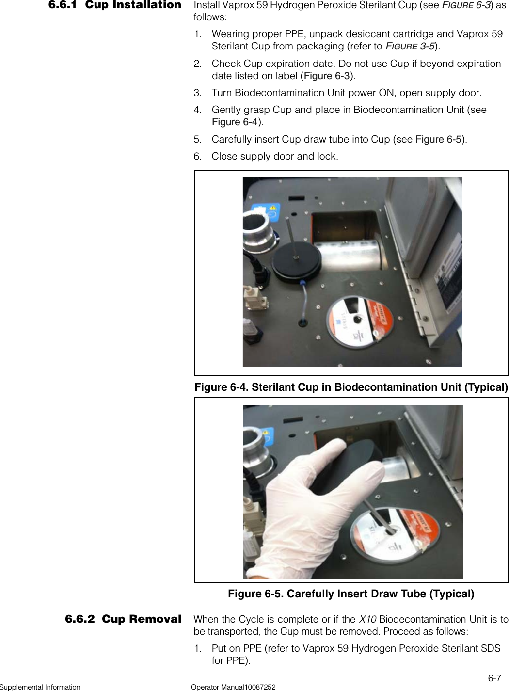
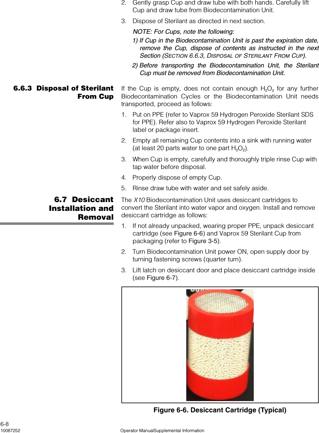
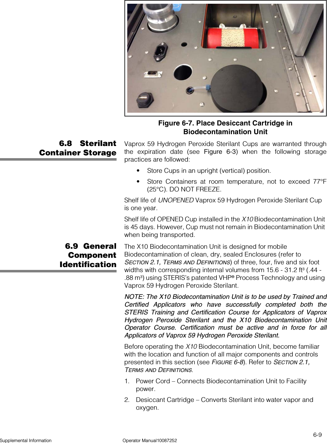
User Manual
Discussion / Help
Navigation