STERIS VHPX10 VHP X10 Biodecontamination Unit User Manual 10087252
STERIS Corporation VHP X10 Biodecontamination Unit 10087252
STERIS >
Contents
- 1. Users Manual
- 2. Updated manual pages
Users Manual
OPERATOR MANUAL
X10™ Biodecontamination Unit
(TEAM) 10087252

i
Introduction Operator Manual 10087252
A WORD FROM STERIS CORPORATION
©2014, STERIS Corporation. All rights reserved. Printed in U.S.A.
Thank you for choosing this fine STERIS Life Sciences product. STERIS
is committed to ensuring your continued satisfaction. This manual
contains important information on proper use and maintenance of the
X10
™
Biodecontamination Unit.
All personnel involved in the use
and maintenance of this equipment must carefully review and
comply with the SAFETY PRECAUTIONS and instructions contained
in this manual and the
Vaprox
®
59
Hydrogen Peroxide Sterilant
Safety Data Sheet (SDS), product label and package insert.
These
instructions are important to protect the health and safety of personnel
operating the X10 Biodecontamination Unit and should be retained in a
conveniently accessible area for quick reference.
Complete instructions for uncrating and installing this unit, as well as
equipment drawings, have been furnished. If missing, contact
STERIS Life Sciences for replacement copies, giving the serial,
equipment and model numbers of the Biodecontamination Unit.
NOTE: Refer to SECTION 2 of this manual for a listing of Terms,
Definitions and Symbols that may appear in this manual or on your
equipment.
Advisory A listing of the SAFETY PRECAUTIONS to be observed when operating
and servicing this X10 Biodecontamination Unit and/or handling the
Sterilant is found in SECTION 1 of this manual or on the container
label. Do not operate or service the equipment or handle the Sterilant
until you have become familiar with this information.
Any alteration of the unit not authorized or performed by STERIS Life
Sciences voids the warranty, could adversely affect Biodecontamination
efficacy, and could violate national, state and local regulations.
Vaprox 59 Hydrogen Peroxide Sterilant have been EPA registered by
STERIS in accordance with Federal Regulations for the specific uses
described in this manual. The X10 Biodecontamination Unit must be
used only on Enclosures (refer to SECTION 2.1, TERMS AND
DEFINITIONS) that have been pre-cleaned and dried per facility
process and current protocols. Please refer to the Vaprox 59
Hydrogen Peroxide Sterilant package insert for additional
information and application instructions.
IMPORTANT: A listing of the
SAFETY PRECAUTIONS
to be observed when operating and servicing this
equipment and/or handling Vaprox 59 Hydrogen Peroxide Sterilant can be found in
SECTION 1
of this
manual. Do not operate or service the equipment or handle the Sterilant until you have been trained
and certified on this information as well as the information on the Vaprox 59 Hydrogen Peroxide
Sterilant product label and package insert.
IMPORTANT: Please refer to SECTION 2.1, TERMS AND DEFINITIONS, for a list of terminology used in
this document. This manual describes the STERIS Biodecontamination Process using
Vaprox 59
Hydrogen Peroxide Sterilant. The U.S. EPA has registered
Vaprox 59
Hydrogen Peroxide Sterilant
(EPA Reg. No. 1043-123) and its use. Refer to either the
Vaprox 59
Hydrogen Peroxide
Sterilant
label and package insert for detailed Safety Precautions and application instructions.

ii
10087252 Operator Manual Introduction
Intended Use NOTE: The X10 Biodecontamination Unit is to be used by Trained
and Certified Applicators who have successfully completed both the
STERIS Training and Certification Course for Applicators of Vaprox
Hydrogen Peroxide Sterilant and the X10 Biodecontamination Unit
Operator Course. Certification must be active and in force for all
Applicators of Vaprox 59 Hydrogen Peroxide Sterilant.
The X10 Biodecontamination Unit is designed for mobile
Biodecontamination of clean, dry, sealed Enclosures (refer to
SECTION 2.1, TERMS AND DEFINITIONS) of three, four, five and six foot
widths with corresponding internal volumes from 15.6 - 31.2 ft3 (.44 -
.88 m3) using STERIS’s patented VHP® Process Technology and
using Vaprox 59 Hydrogen Peroxide Sterilant.
Uses other than as specified and described in this manual are not
recommended and may not be effective or safe in operating the
Biodecontamination Unit. Consult this manual or STERIS Life
Sciences for further information.
The Biodecontamination Unit utilizes specially designed disposable
70 mL Cups* of Vaprox 59 Hydrogen Peroxide Sterilant.
*Available separately for purchase.
Introduction The STERIS X10 Biodecontamination Unit offers fast, economical
Biodecontamination of Enclosures (refer to SECTION 2.1, TERMS AND
DEFINITIONS).
The Biodecontamination Unit uses STERIS's patented VHP Process
Technology. This process utilizes hydrogen peroxide vapor as a
broad spectrum anti-microbial without condensation of the active
ingredient onto surfaces with good material compatibility.
The Biodecontamination Unit comes with two programmed cycles
designed to achieve a minimum of a 6-log bioburden reduction in a
Class II Type A2 Biological Safety Cabinet:
1. Cycle 1 for 3 - 4' (0.9 - 1.2 m)
2. Cycle 2 for 5 - 6' (1.5 - 1.8 m)
The X10 features X-Phase hardware technology and VaproxLink
software technology. X-Phase hardware technology features a
rotating cylinder design that enables heating, dehumidification,
conditioning, Biodecontamination and aeration for an All-In-One unit
design while VaproxLink software technology automatically identifies
Vaprox 59 Hydrogen Peroxide Sterilant Cup and verifies expiration
date.
With 0.5-2.5 g/min of Sterilant injection, the Biodecontamination Unit
is capable of Biodecontaminating a single Class II Type A2 cabinet
from 3 - 6' (0.9 - 1.8 m) with internal cabinet volume up to 31.2 ft3
(.88 m3).
The X10 Biodecontamination Unit is multi-lingual (English, French,
Spanish, Italian and German) and available in either 120 or 230 Vac,
single phase, electrical service.
DANGER – FIRE AND
EXPLOSION HAZARD:
• Verify all materials coming
in contact with hydrogen
peroxide are compatible
with oxidizers. Contact
STERIS Life Sciences or
the material manufacturer
for information on material
compatibility.
• This Biodecontamination
Unit is not designed to
process flammable liquids.
Do not process liquids,
linens, powders or any
cellulose materials.
Process only those
materials compatible with
hydrogen peroxide.

iii
Introduction Operator Manual 10087252
Service Information
A thorough preventive maintenance program is essential to safe and
proper equipment operation. Comprehensive instructions for monthly,
quarterly and semi-annual preventive maintenance can be found in the
Maintenance Manual (available from STERIS Life Sciences).
Only STERIS-trained personnel should attempt to perform maintenance
on the X10 Biodecontamination Unit to avoid personal injury, improper
equipment performance, invalidation of the warranty or other costly
damage.
Customers are encouraged to contact STERIS Life Sciences concerning
our annual maintenance program. Under the terms of the program,
preventive maintenance, adjustments and replacement of worn parts are
provided on a scheduled basis to help ensure optimal equipment
performance and to help minimize untimely or costly schedule
interruptions. STERIS Life Sciences maintains a worldwide staff of well-
equipped, factory-trained technicians to provide these services, as well
as on-site installation, training and expert repair services. Contact
STERIS Life Sciences** for details.
**1 (800) 440-9009 or www.sterislifesciences.com.

iv
10087252 Operator Manual Introduction
The base language of this document is
ENGLISH. Any translations must be
made from the base language document.
EC Authorized Re
p
resentative
STERIS Ltd.
Chancery House
190 Waterside Road
Hamilton Industrial Park
Leicester LE5 1QZ UK
STERIS Cor
p
oratio
n
5
960 Heisle
y
Roa
d
Mentor,
O
H 44060-1834 U
SA
44
0
-
3
54-
2600
•
800
-444-
9009
www.
s
t
e
r
is
.
com
STERIS CORPORATION
6515 Hopkins Road
Mentor, OH 44060 • USA

v
Table of Contents Operator Manual 10087252
TABLE OF CONTENTS
Section
Number Description Page
1 Safety Precautions ........................................................................................................................ 1-1
2 Terms, Definitions and Symbols.................................................................................................. 2-1
2.1 Terms and Definitions ............................................................................................................................ 2-1
2.2 Symbols ................................................................................................................................................. 2-3
3 Operating Instructions .................................................................................................................. 3-1
3.1 Introduction ............................................................................................................................................ 3-1
3.2 Operation ............................................................................................................................................... 3-2
3.2.1 Attach to Enclosure .................................................................................................................. 3-2
3.2.2 Prepare Enclosure and Biodecontamination Unit..................................................................... 3-4
3.2.3 Cycle Completion ..................................................................................................................... 3-6
4 Troubleshooting ............................................................................................................................ 4-1
4.1 Troubleshooting ..................................................................................................................................... 4-1
5 Routine Maintenance..................................................................................................................... 5-1
5.1 Read Before Performing Routine Maintenance ..................................................................................... 5-1
5.2 Clean Biodecontamination Unit ............................................................................................................. 5-2
5.3 Clean Hoses .......................................................................................................................................... 5-3
5.4 Cleaning Touch Screen ......................................................................................................................... 5-4
5.5 Replacement Parts and Supplies .......................................................................................................... 5-4
5.5.1 Ordering Information ................................................................................................................ 5-4
5.5.2 Supply Products ....................................................................................................................... 5-5
5.5.3 Recommended Spare Parts ..................................................................................................... 5-5
5.6 Associated Publications........................................................................................................................ 5-6
6 Supplemental Information ............................................................................................................ 6-1
6.1 Installation Verification........................................................................................................................... 6-1
6.1.1 Installation Checklist................................................................................................................. 6-1
6.1.2 Pre-Operation Checklist ........................................................................................................... 6-1
6.2 Technical Data ....................................................................................................................................... 6-2
6.2.1 Overall Size (W x H x D) .......................................................................................................... 6-2
6.2.2 Weight ...................................................................................................................................... 6-2
6.2.3 Electric Requirements .............................................................................................................. 6-2
6.2.4 Environmental Conditions ........................................................................................................ 6-2
6.3 Hydrogen Peroxide Biodecontamination ............................................................................................... 6-3
6.4 Biodecontamination Cycle ..................................................................................................................... 6-3
6.5 Hydrogen Peroxide Handling Precautions ............................................................................................. 6-5

vi
10087252 Operator Manual Table of Contents
Section
Number Description Page
TABLE OF CONTENTS (CONT’D)
6.6 Sterilant Cup Installation and Removal................................................................................................. 6-6
6.6.1 Cup Installation......................................................................................................................... 6-7
6.6.2 Cup Removal............................................................................................................................ 6-7
6.6.3 Disposal of Sterilant From Cup ................................................................................................ 6-8
6.7 Desiccant Installation and Removal....................................................................................................... 6-8
6.8 Sterilant Container Storage .................................................................................................................. 6-9
6.9 General Component Identification ......................................................................................................... 6-9
6.10 Operation ............................................................................................................................................. 6-10

vii
Table of Contents Operator Manual 10087252
LIST OF FIGURES
Description Page
Figure 3-1. VHP X10 Biodecontamination Unit in Cases ..............................................................................3-3
Figure 3-2. Open Biodecontamination Unit Case..........................................................................................3-3
Figure 3-3. Accessory Case Components ....................................................................................................3-3
Figure 3-4. Connect Biodecontamination Unit to Enclosure .........................................................................3-4
Figure 3-5. Open Supply Door ......................................................................................................................3-5
Figure 3-6. Connecting X10 Biodecontamination Unit and AR60 Aerator to Enclosure ...............................3-6
Figure 6-1. X10 Biodecontamination Unit .....................................................................................................6-3
Figure 6-2. Typical Biodecontamination Cycle..............................................................................................6-4
Figure 6-3. Typical Sterilant Cup...................................................................................................................6-6
Figure 6-4. Sterilant Cup in Biodecontamination Unit (Typical) ....................................................................6-7
Figure 6-5. Carefully Insert Draw Tube (Typical) ..........................................................................................6-7
Figure 6-6. Desiccant Cartridge (Typical) .....................................................................................................6-8
Figure 6-7. Place Desiccant Cartridge in Biodecontamination Unit ..............................................................6-9
Figure 6-8. Component Identification ..........................................................................................................6-10

viii
129396-083 Operator Manual Table of Contents
Life
Sciences

xi
Table of Contents Operator Manual 10087252
LIST OF TABLES
Table
Number Description Page
Table 2-1 Definition of Symbols....................................................................................................................... 2-3
Table 4-1 Alarm/Abort Actions......................................................................................................................... 4-1
Table 4-2 Power Interruption/Power-Up Actions ............................................................................................. 4-1
Table 4-3 Troubleshooting Guide .................................................................................................................... 4-2
Table 5-1 VHP X10 Biodecontamination Unit Selected Supply Products ....................................................... 5-5
Table 5-2 Recommended Spare Parts ............................................................................................................ 5-5
Table 5-3 Associated Publications .................................................................................................................. 5-6

xii
10087252 Operator Manual Table of Contents
Life
Sciences

1-1
Safety Precautions Operating Manual 10087252
1
NOTE: Refer to SECTION 2 of this manual for a listing of Terms, Definitions and Symbols that may appear in this
manual or on your equipment.
The following Safety Precautions must be observed when operating or servicing this STERIS X10™
Biodecontamination Unit and when handling Vaprox® 59 Hydrogen Peroxide Sterilant Cups. Safety Precautions
are divided as follows:
•DANGER indicates personal injury or substantial property damage results if proper precautions are not
taken.
•WARNING indicates the potential for personal injury and/or potential for property damage may result if proper
precautions are not taken.
•CAUTION indicates the potential for damage to equipment may result if proper precautions are not taken.
For emphasis, certain Safety Precautions are repeated throughout the manual. It is important to review ALL
Safety Precautions before operating or servicing the unit. Also read the Vaprox 59 Hydrogen Peroxide
Sterilant SDS for additional information on the proper use and handling of hydrogen peroxide.
STERIS recommends that all operators should be regularly trained in the operation and safe usage of the
equipment, including emergency procedures for any harmful material released into the environment. Records of
attendance at training shall be maintained and evidence of understanding shall be demonstrated.
NOTE:
Disregarding the presented safety information is considered
ABNORMAL USE
of this product. If the
equipment is used in a manner not specified by STERIS, the protection provided by the equipment may be impaired.
DANGER – SLIPPING HAZARD:
DANGER – FIRE AND EXPLOSION HAZARD:
Water or hydrogen peroxide spilled on the floor presents a slipping hazard – promptly clean up the spill.
If in doubt whether the liquid is water or hydrogen peroxide, test the liquid using a Liquid Hydrogen
Peroxide Test Strip (follow manufacturer's instructions), before wiping up. If the liquid is hydrogen
peroxide, contain the spill and dilute with water (at least 20 parts water to one part H2O2) prior to wiping
up. Observe all hydrogen peroxide handling precautions. Refer to the Vaprox 59 Hydrogen Peroxide
Sterilant SDS for spill containment and cleanup.
Liquid hydrogen peroxide is a strong oxidant and poses a FIRE, EXPLOSION OR CONTAINER
RUPTURE HAZARD. Avoid excessive heat, contamination or contact with combustible materials.
Clothing, shoes or other combustible materials that have come in contact with hydrogen peroxide must
be immediately and thoroughly washed with water. Discard shoes contaminated with Vaprox 59 Hydrogen
Peroxide Sterilant in a fireproof container. If Vaprox Sterilant is allowed to dry in the materials, a fire may
result. IN CASE OF FIRE, use water only. CONTAIN SPILLS and dilute with water (at least 20 parts
water to one part H2O2). After diluting the spill, sodium metabisulfide or sodium sulfite (1.9 lb of SO2
equivalent per 500 mL of H2O2) may be used to destroy the peroxide. SEE SDS FOR ADDITIONAL
INFORMATION. EFFECTS MAY BE DELAYED.
Verify all materials coming in contact with hydrogen peroxide, especially the concentrated liquid, are
compatible with oxidizers. Contact STERIS Life Sciences or the material manufacturer for information
on material compatibility.
This Biodecontamination Unit is not designed to process flammable liquids. Do not process liquids,
linens, powders or any cellulose materials. Process only those materials compatible with hydrogen
peroxide.
SAFETY PRECAUTIONS 1
1-2
10087252 Operating Manual Safety Precautions
DANGER – PERSONAL INJURY, CONTAMINATED ENCLOSURE AND/OR EQUIPMENT
DAMAGE HAZARD:
DANGER – CHEMICAL INJURY HAZARD:
Use only Vaprox 59 Hydrogen Peroxide Sterilant Containers, containing STERIS-registered hydrogen
peroxide which has been specially formulated, tested and approved for use in this X10
Biodecontamination Unit. Vaprox 59 Hydrogen Peroxide Sterilant has been registered by STERIS in
accordance with U.S. Federal Regulations for the specific uses described in this manual. Use of other
materials and/or H2O2 other than Vaprox 59 Hydrogen Peroxide Sterilant could impair equipment
operation, result in costly repairs, result in an ineffective Biodecontamination Cycle, violate federal law
and void the equipment warranty.
Before using Vaprox 59 Hydrogen Peroxide Sterilant, check the expiration date. Do not use a Sterilant
if it is beyond its expiration date, or if it will not be fully used before its expiration date.
When using a Vaprox 59 Hydrogen Peroxide Sterilant Cup, always wear appropriate Personal Protective
Equipment (refer to Vaprox 59 Hydrogen Peroxide Sterilant SDS for PPE), keep the Cup upright and
do not squeeze.
Before disposing of a Vaprox 59 Hydrogen Peroxide Sterilant Cup, empty all remaining Cup contents
into a sink with running water (at least 20 parts water to one part Vaprox H2O2), then carefully triple rinse
the Cup with tap water.
Before starting a cycle, check Sterilant to ensure it is not expired.
No one may open a sealed Enclosure during or after an aborted cycle without PPE (refer to Sterilant SDS
for PPE) if Sterilant levels within the treated Enclosure are above one PPM. Refer to Sterilant label and
package insert for instructions.
When handling hydrogen peroxide, wear appropriate PPE (refer to Vaprox 59 Hydrogen Peroxide
Sterilant SDS for PPE) and observe all Safety Precautions. See Vaprox 59 Hydrogen Peroxide Sterilant
SDS, product label and package insert for additional handling information.
CORROSIVE. Causes irreversible eye damage or skin burns. May be fatal if inhaled. Harmful if swallowed
or absorbed through the skin. Do not get in eyes, on skin or on clothing. Do not breathe spray mist. Prolonged
or frequently repeated skin contact may cause allergic reaction in some individuals. User should wash
hands before eating, drinking, chewing gum, using tobacco or using the toilet. User should remove
contaminated clothing and wash before reuse. Applicators and all other handlers must wear PPE (refer to
Vaprox 59 Hydrogen Peroxide Sterilant SDS for PPE). See Vaprox 59 Hydrogen Peroxide Sterilant product
label and package insert for additional handling information.
When handling the Biodecontamination System hoses, wear appropriate PPE (refer to Vaprox 59
Hydrogen Peroxide Sterilant SDS for PPE). Any visible liquid in the hoses must be treated as concentrated
hydrogen peroxide and all hydrogen peroxide handling precautions must be observed.
If power has been interrupted, do not attempt to access the Enclosure (refer to SECTION 2.1, TERMS AND
DEFINITIONS). Hydrogen peroxide may be present in the Enclosure.
Read the manufacturer operating instructions before attempting to use the low level hydrogen peroxide
monitor.

1-3
Safety Precautions Operating Manual 10087252
DANGER – CHEMICAL INJURY HAZARD (Cont’d):
When handling Vaprox 59 Hydrogen Peroxide Sterilant Cups, note the following:
• Use extreme caution when handling a damaged, leaking or expired hydrogen peroxide Cup. Always
wear appropriate PPE (refer to Vaprox 59 Hydrogen Peroxide Sterilant SDS for PPE) when
handling damaged, leaking or expired Cups, or when wiping up hydrogen peroxide spills.
• When handling a Cup under water, do not allow your glove openings to go below the surface of the
water permitting liquid to enter the gloves.
• A Vaprox 59 Hydrogen Peroxide Sterilant Cup must be in the Cup holder at all times. When no Cup
is in place, concentrated liquid hydrogen peroxide may drip from the Cup connector.
Before running a Biodecontamination Cycle, always verify that the Biodecontamination Unit is properly
connected to the sealed Enclosure (refer to SECTION 2.1, TERMS AND DEFINITIONS) to ensure complete
containment of the hydrogen peroxide vapors (check hose connections and ensure all Enclosure vents/
ports are sealed). Post warning signs on and around the treated Enclosure to prevent accidental entry
during the Biodecontamination Cycle. Refer to the Vaprox 59 Hydrogen Peroxide Sterilant label and
package insert for specific detailed instructions.
When the control panel warning light is ON, harmful Sterilant vapors are present within the Enclosure
(refer to SECTION 2.1, TERMS AND DEFINITIONS). Do not access the Enclosure. If it is necessary to access
the Enclosure being processed under these conditions before the end of the Aeration phase or after an
aborted Cycle, wear appropriate PPE (refer to Vaprox 59 Hydrogen Peroxide Sterilant SDS for PPE).
Ensure no skin is exposed. Follow all re-entry protocols listed on the Vaprox 59 Hydrogen Peroxide
Sterilant label and package insert.
At the end of the Aeration phase, use a low level hydrogen peroxide monitor to check and periodically
monitor the hydrogen peroxide vapor concentration within the Enclosure (refer to SECTION 2.1, TERMS
AND DEFINITIONS). The hydrogen peroxide vapor concentration should be at or below established levels
before the Enclosure is accessed by Trained and Certified Applicators. The Vaprox 59 Hydrogen Peroxide
Sterilant label and package insert contain required hydrogen peroxide limits for re-entry and releasing
of the Enclosure after Biodecontamination.
Any visible liquids in the Enclosure (refer to SECTION 2.1, TERMS AND DEFINITIONS) must be treated as
concentrated hydrogen peroxide. Always test residual liquids, using a Liquid Hydrogen Peroxide test
strip (follow manufacturer's instructions), before diluting and wiping up. Observe all hydrogen peroxide
handling precautions presented in the Vaprox 59 Hydrogen Peroxide Sterilant SDS, product label and
package insert.
The Biodecontamination Unit generates harmful hydrogen peroxide vapor and discharges it from the
Outlet port. Always ensure all connections are vapor tight and that the Enclosure (refer to SECTION 2.1,
TERMS AND DEFINITIONS) is properly sealed, secured and placarded as described on the Vaprox 59
Hydrogen Peroxide Sterilant label and package insert. Heed this Safety Precaution to ensure, under
normal conditions, the Biodecontamination Unit and Enclosure do not leak H2O2 vapor.
1-4
10087252 Operating Manual Safety Precautions
WARNING – PERSONAL INJURY AND/OR EQUIPMENT DAMAGE HAZARD:
WARNING – ELECTRIC SHOCK HAZARD:
CAUTION – POSSIBLE EQUIPMENT DAMAGE:
REMEMBER – POSSIBLE TIME DELAY:
Repairs and adjustments to this equipment must be made only by STERIS Life Sciences or STERIS-
trained service personnel. Maintenance performed by unqualified personnel or installation of
unauthorized parts could cause personal injury, impair equipment protection design, result in improper
equipment performance, invalidate the warranty or result in costly damage. Contact STERIS Life
Sciences regarding service options.
Regularly scheduled preventive maintenance is required for safe and reliable operation of this equipment.
Contact STERIS Life Sciences to schedule preventive maintenance.
Lifting the Biodecontamination Unit requires more than one person. The unit weighs approximately 68 lb
(31 kg).
Place the Biodecontamination Unit only on flat surfaces. Various internal components are designed for
operation when Unit is placed on a level, flat surface.
Ensure the Biodecontamination Unit is positioned so access to power switch and facility outlet are not
restricted. To disconnect Biodecontamination Unit, pull cord from facility outlet. The power switch is NOT
intended to be used as a means of disconnect.
Integrated (temperature and humidity) sensors are fragile. Do not bang, twist or crush. Biodecontamination
Unit does not operate properly with a damaged sensor.
Disconnect electrical power source to equipment (pull plug from facility outlet) before attempting to
access the
Biodecontamination Unit
. The power switch is NOT intended to be used as a means of
disconnect.
Use nonabrasive cleaners when cleaning unit. If you need technical assistance or additional instructions,
call STERIS Life Sciences.
• Follow all directions on container.
• Do not use abrasive cleaners on plastic surfaces.
• Avoid detergents with bases, aromatics, ketones, esters and chlorinated hydrocarbons.
• Avoid contacting plastic surfaces with greases and oils.
Keep connecting hoses off the floor. If supply connecting hoses rest on cool floors or other cool surfaces,
hydrogen peroxide may condense in the hoses. Place a support under the hoses (e.g., lash hoses to
plastic easel or plastic tripod) to prevent kinks and undue strain on the hose connections.
Use only Distilled Water for the hydrogen peroxide piping purge. Use of tap water will damage the
vaporizer.
Insufficient clearance space will make repairs more difficult and time-consuming. Refer to the equipment
drawing for minimum clearance for service/maintenance access requirements.

2-1
Terms, Definitions and Symbols Operator Manual 10087252
2.1 Terms and
Definitions
Aeration – Final phase of a Biodecontamination Cycle. Allows for re-
entry into treated, sealed Enclosures once the Sterilant concentration
levels are at or below permissible levels. Typical H2O2 concentration
≤1 PPM.
BI – Biological Indicator used for Biodecontamination Cycle
evaluation. Typically E6 Geobacillus stearothermophilus is used.
Biodecontamination1 – Third phase of the Biodecontamination Cycle
or the obtaining of bioburden reduction targets in a sealed Enclosure.
Biodecontamination Cycle1 – Represents the complete process
(Biodecontamination) from start to finish which may include
Dehumidify, Condition, Biodecontamination and Aeration phases.
Biodecontamination Unit – STERIS X10™ Biodecontamination Unit.
Catalytic Converter – A component of the Biodecontamination Unit
utilizing a catalyst to degrade H2O2 into water vapor and oxygen.
CI – Chemical Indicator used for Biodecontamination Cycle validation
and Sterilant mapping.
Condition – Second phase of the Biodecontamination Cycle. Sterilant
is added to the sealed Enclosure to reach the target concentration
needed for the Biodecontamination phase.
Cup – Vaprox® 59 Hydrogen Peroxide Sterilant container, 70 mL.
Dehumidify – First phase of the Biodecontamination Cycle. Achieves
temperature and humidity conditions necessary for subsequent
Biodecontamination phases.
Enclosure – Contained area to be Biodecontaminated (e.g., Class II
Type A2 Biosafety Cabinet).
FMP – Fumigation Management Plan.2
HMI – Human Machine Interface (such as the control display).
H2O2 or H2O2 – Hydrogen peroxide.
I/O – Input/Output.
PLC – Programmable Logic Controller.
1When using STERIS X10 Biodecontamination Units with Vaprox 59 Hydrogen Peroxide Sterilant in the United States, the term
Biodecontamination referred to in this Operator Manual is defined as Sterilization of exposed porous and non-porous surfaces in a precleaned,
dry, sealed Enclosure. Any reference to Biodecontamination as it relates to the use of this equipment in the United States does not impart
additional claims of effectiveness beyond that approved in the EPA registered labeling of Vaprox 59 Hydrogen Peroxide Sterilant for use on
precleaned, dry, exposed porous and non-porous surfaces in a sealed Enclosure.
2Guidance for developing a suitable Fumigation Management Plan can be found in STERIS publication (P129383-938) or searching EPA
website (epa.gov) for the key words ’Vaprox Package Insert.’
Continued ...
TERMS, DEFINITIONS AND SYMBOLS 2

2-2
10087252 Operator Manual Terms, Definitions and Symbols
Terms and Definitions
(Cont’d)
PPE – Personal Protective Equipment including goggles or face
shield, chemical-resistant gloves (barrier laminate, butyl rubber, nitrile
rubber, neoprene rubber, polyvinyl chloride, or Viton®3) and SCBA
(Self-Contained Breathing Apparatus) if hydrogen peroxide
concentrations exceed one ppm during handling/or application of
Sterilant. Refer to Vaprox 59 Hydrogen Peroxide Sterilant SDS for
appropriate PPE.
RH – Relative Humidity.
SCBA – Self-Contained Breathing Apparatus.
scfm – Standard Cubic Feet per Minute.
scmh – Standard Cubic Meters per Hour.
SDS – Material Data Sheet.
Sporicidal – Antimicrobial activity which destroys or eliminates all
forms of microbial life including hard-to-kill microbial spores.
SSR – Solid State Relay.
Sterilant – Vaprox 59 Hydrogen Peroxide Sterilant (STERIS EPA-
registered, 1043-123, 59%). Sterilant contains stabilizers and other
additives making it suitable for STERIS VHP Biodecontamination
Units.
Sterilization – Complete killing of all microbial life including spores.
Unit – Biodecontamination Unit.
USB – Universal Serial Bus. Industry standard defining cables,
connectors and communication protocols used in a bus for
connection, communication and power supply between computers
and electronic devices.
Vac – Volts Alternating Current.
Vdc – Volts Direct Current.
VHP – STERIS proprietary process technology utilizing H2O2 vapor as
a broad spectrum anti-microbial without condensation of the active
ingredient on the surfaces.
3 Viton is a registered trademark of DuPont Performance Elastomers.
2-
3
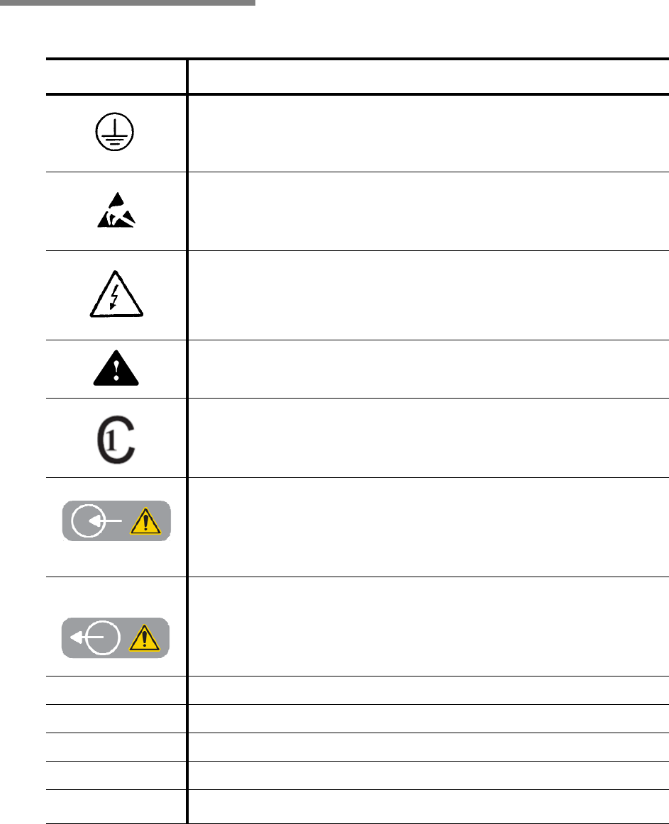
2.2 Symbols Table 2-1 contains symbols which may appear on your STERIS X10
Biodecontamination Unit components.
Table 2-1. Definition of Symbols
Symbol Definition
Protective Earth (Ground)
Electrostatic Sensitive Device
Electric Shock Hazard
Attention, Consult Manual for Further Instructions
This Product Has Been Tested To The Requirements Of CAN/CSA-C22.2
No. 61010-1, Second Edition, Including Amendment 1, Or A Later Version
Of The Same Standard Incorporating The Same Level Of Testing
Requirements
Inlet Sterilant Hose Connection (From Enclosure Exhaust Into
Biodecontamination Unit)
Outlet Sterilant Hose Connection (From Biodecontamination Unit Into
Enclosure Work Area)
SN Serial Number of Unit
V~ Voltage Rating of Unit, Alternating Current
AAmperage Rating of Unit
Hz Frequency Rating of Unit
φPhase of Unit

2-4
10087252 Operator Manual Terms, Definitions and Symbols
Life
Sciences
3-1
Operating Instructions Operator Manual 10087252
NOTE: Uses other than as specified and described in this section, on
the Sterilant label and/or package insert are not recommended, may
not be effective in Biodecontamination, and may not be safe. Please
contact STERIS Life Sciences for appropriate guidance, in-service
and training.
3.1 Introduction NOTE: Refer to SECTION 2 of this manual for a listing of Terms,
Definitions and Symbols that may appear in this manual or on your
equipment.
The STERIS VHP X10
™
Biodecontamination Unit, using STERIS's
patented VHP Process Technology, offers fast, economical
biodecontamination of Enclosures.
This process utilizes H
2
O
2
vapor as a broad spectrum anti-microbial.
There is no condensation of the active ingredient onto surfaces and
Sterilant has good material compatibility.
The Biodecontamination Unit comes with two programmed cycles
designed to achieve a minimum of a 6-log bioburden reduction in an
Enclosure (Class II Type A2 Biological Safety Cabinet):
•Cycle 1 - 3 - 4' (0.9 - 1.2 m)
•Cycle 2 - 5 - 6' (1.5 - 1.8 m)
The STERIS X10 Biodecontamination Unit features X-Phase hardware
technology and VaproxLink software technology. X-Phase hardware
technology features a rotating cylinder design that enables heating and
Biodecontamination Cycle phases (Dehumidification, Conditioning,
Biodecontamination and Aeration) for an All-In-One unit design while
VaproxLink software technology automatically identifies Vaprox
®
59
Hydrogen Peroxide Sterilant Cup and verifies expiration date.
Other X10 Biodecontamination Unit features:
• With 0.5 - 2.5 g/min of Sterilant injection, the Biodecontamination
Unit is capable of Biodecontaminating a single Class II Type A2
cabinet from 3 - 6' (0.9 - 1.8 m) with an internal cabinet volume of
up to 31.2 ft3 (.88 m3).
• Biodecontamination Unit operates outside (with the addition of
Sash Support Plate and Exhaust Plenum Adapter) the Enclosure
and can operate as a stand alone Biodecontamination Unit.
IMPORTANT: A listing of the
SAFETY PRECAUTIONS
to be observed when operating and servicing this
equipment and/or handling Vaprox
®
59 Hydrogen Peroxide Sterilant can be found in
SECTION 1
of
this manual. Do not operate or service the equipment or handle the Sterilant until you have been
trained and certified on this information as well as the information on the Vaprox 59 Hydrogen
Peroxide Sterilant product label and package insert.
IMPORTANT: Please refer to SECTION 2.1, TERMS AND DEFINITIONS, for a list of terminology used in
this document. This manual describes the STERIS Biodecontamination Process using
Vaprox 59
Hydrogen Peroxide Sterilant. The U.S. EPA has registered
Vaprox 59
Hydrogen Peroxide Sterilant
(EPA Reg. No. 1043-123) and its use. Refer to either the
Vaprox 59
Hydrogen Peroxide
Sterilant
label and package insert for detailed Safety Precautions and application instructions.
OPERATING INSTRUCTIONS 3

3-2
10087252 Operator Manual Operating Instructions
• All Biodecontamination Cycle data is output to a USB interface in
encrypted format for data storage.
• Biodecontamination Unit is easily transported in a light weight
and IP20 rated case (with retractable handle and wheels).
•A separate AR60
™ Aerator is available for catalyzing sterilant for
applications requiring faster aeration time.
• The X10 Biodecontamination Unit is multi-lingual (English,
French, Spanish, Italian and German) and available in either 120
or 230 Vac, single phase electrical service.
• To minimize exposure to liquid Sterilant during handling, the
system uses specially designed disposable Cups containing
approximately 70 mL of Vaprox 59 Hydrogen Peroxide Sterilant.
3.2 Operation NOTE: The STERIS X10 Biodecontamination Unit is to be used by
Trained and Certified Applicators who have successfully completed
both the STERIS Training and Certification Course for applicators of
Vaprox 59 Hydrogen Peroxide Sterilant and the STERIS X10
Biodecontamination Unit Operator Course. Certification must be
active and in force for all Applicators of Vaprox 59 Hydrogen Peroxide
Sterilant.
3.2.1 Attach to Enclosure The following information is intended to enable a Trained and
Certified Applicator to properly attach the Biodecontamination Unit
to an Enclosure (refer to SECTION 2.1, TERMS AND DEFINITIONS):
1. Review site-specific FMP* and verify all accessories are present
(if applicable) and proper location of Biodecontamination Unit.
2. Consult with facility officials on Safety Precautions, security,
warning placards and other facility requirements.
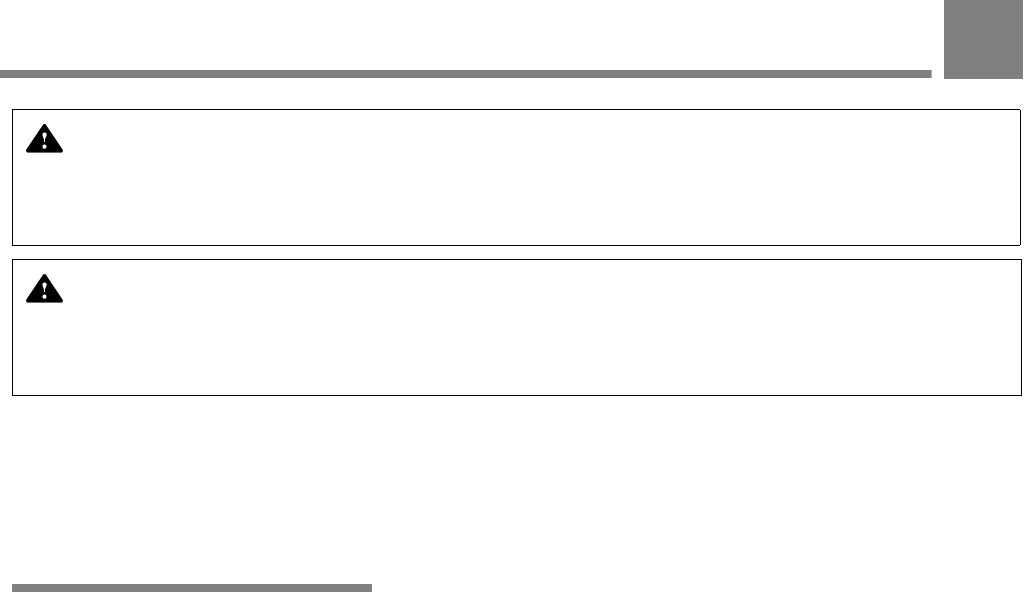
3. Position Biodecontamination Unit and any needed accessories
cases near Enclosure (see Figure 3-1).
NOTE: Ensure Biodecontamination Unit is within 10’ (3 m) of the
facility power outlet. Use of extension cords is not recommended.
*Guidance for developing a suitable Fumigation Management Plan can be found in
STERIS publication (P129383-938) or searching EPA website (epa.gov) for the key
words ’Vaprox Package Insert.’
WARNING – PERSONAL INJURY AND/OR EQUIPMENT DAMAGE HAZARD:
• Lifting Biodecontamination Unit requires more than one person. The unit weighs approximately 68 lb
(31 kg).
• Place the Biodecontamination Unit only on flat surfaces. Various internal components are
designed for operation when Unit is placed on a level, flat surface.
• Ensure the Biodecontamination Unit is positioned so access to power switch and facility outlet
are not restricted.
• Integrated (temperature and humidity) sensors are fragile. Do not bang, twist or crush.
Biodecontamination Unit does not operate properly with a damaged sensor.
3-3
Operating Instructions Operator Manual 10087252
Figure 3-1. VHP X10 Biodecontamination Unit in Cases
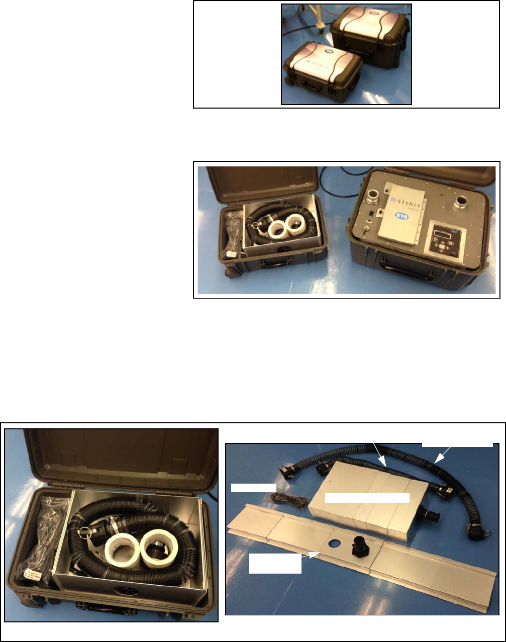
4. Unlatch (all six) Biodecontamination Unit case cover and lift cover
(see Figure 3-2).
Figure 3-2. Open Biodecontamination Unit Case
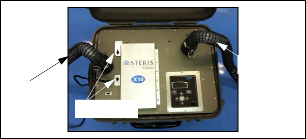
5. Open Accessories Case (see Figure 3-3) and unpack accessories:
• Inlet Hose Assembly
• Outlet Hose Assembly
• Sash Support Plate Assembly
• Exhaust Plenum Adapter
• Power Cord (Either 120V or 230V).
Figure 3-3. Accessory Case Components
M
Power Cord
Sash Support
Plate Assembly
Exhaust Plenum Adapter
Inlet Hose Assembly
Outlet Hose
Assembly
3-4
10087252 Operator Manual Operating Instructions
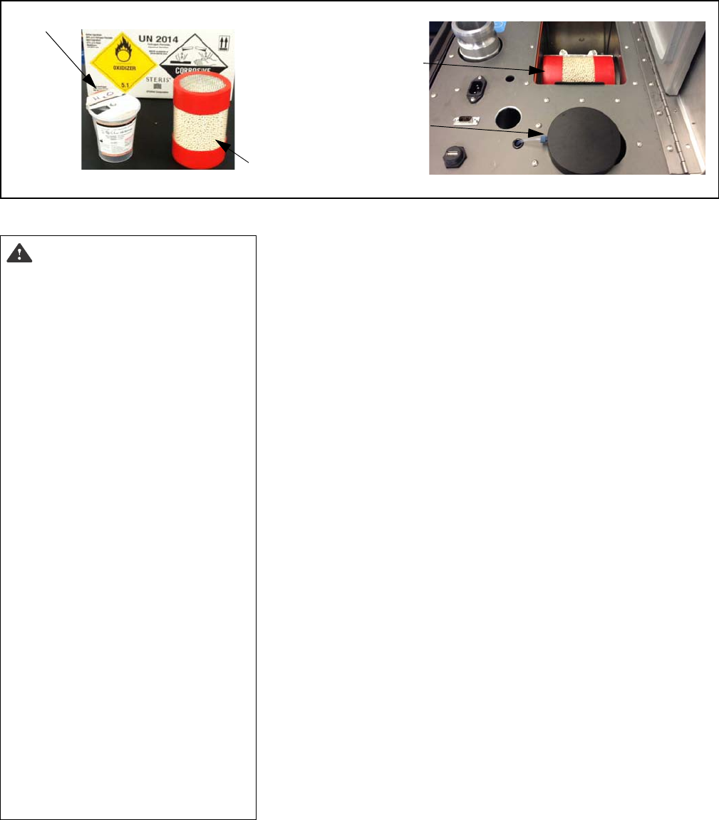
6. Attach Sash Plate Assembly to Enclosure.
7. Attach Exhaust Plenum Adapter to Enclosure.
8. Connect hoses from VHP X10 Biodecontamination Unit to
Enclosure (see Figure 3-4). Follow labels on Biodecontamination
Unit.
Figure 3-4. Connect Biodecontamination Unit to Enclosure
3.2.2 Prepare Enclosure and
Biodecontamination Unit
The following information is intended to enable a Trained and Certified
Applicator to properly set-up the Biodecontamination Unit and prepare
the Enclosure (refer to
SECTION 2.1, TERMS AND DEFINITIONS
):
1. Per FMP*, make all necessary preparations to Enclosure. Verify
CIs and BIs are placed inside Enclosure as required.
*Guidance for developing a suitable Fumigation
Management Plan can be found in STERIS
publication (P129383-938) or searching EPA
website (epa.gov) for the key words ’Vaprox
Package Insert.’
2. Wearing proper PPE, unpack desiccant cartridge and Vaprox 59
Sterilant Cup from packaging (see Figure 3-5).
3. Ensure Sterilant Cup is not expired.
4. Plug Biodecontamination Unit power cord into proper facility
outlet (120 Vac, 20A or 230 Vac, 10A; single source circuit).
5. Turn Biodecontamination Unit power ON,
6. Use Arrow Keys to highlight SELECT CYCLE on display. Press
Start button to continue.
7. Use Arrow Keys to highlight desired cycle on display. Press
Start button to continue.
8. If cycle option asks, set date and time.
9. If cycle option asks, select language.
10. Follow screen prompt, open door and insert Sterilant Cup and
desiccant cartridge into unit (see Figure 3-5).
NOTE: Refer to SECTION 6.6, STERILANT CUP INSTALLATION AND
REMOVAL, and SECTION 6.7, DESICCANT INSTALLATION AND
REMOVAL, for more information of desiccant cartridge and
Sterilant Cup insertion.
11. Follow screen prompt, press Start.
To Sash Plate
Assembly
To Exhaust Plenum
Adapter
Supply Door
Fastening Screws
3-5
Operating Instructions Operator Manual 10087252
Figure 3-5. Open Supply Door
12. Follow screen prompt, insert USB device or press Start.
13. Follow display commands as cycle proceeds (refer to
SECTION 6.4, BIODECONTAMINATION CYCLE).
14. At completion of HOLD phase, MANDATORY AERATION (5
minutes) phase starts.
15. At completion of MANDATORY AERATION, if optional aeration is
desired, press Cancel. Proceed as follows:
a. Control asks, USE EXTERNAL AERATOR?
b. Turn Enclosure fan OFF.
c. Position VHP AR60™ Aerator near Enclosure.
d. Disconnect Outlet and Inlet Hose Assemblies from
Biodecontamination Unit and connect to AR60 Aerator (see
Figure 3-6).
e. Plug AR60 Aerator into applicable wall outlet (120 or
230 Vac).
f. Turn AR60 Aerator ON by pressing power switch.
g. Turn Enclosure fan ON.
h. Press Check button.
i. Allow AR60 Aerator to operate until H2O2 is reduced to a safe
level of less than or equal to 1 PPM.
16. At completion of MANDATORY AERATION, if optional aeration is
not desired, control continues with AERATION phase.
17. Cycle completes, alarm sounds and control displays
COMPLETE - PRESS KEY. Press Check button.
18. Proceed to next section.
Sterilant Cup
For Desiccant
Cartridge
For Sterilant
Cup
Desiccant
Cartridge
DANGER – CHEMICAL
INJURY HAZARD:
• When handling the
Biodecontamination System
hoses, wear appropriate
PPE (refer to Vaprox 59
Hydrogen Peroxide Sterilant
SDS for PPE). Any visible
liquid in the hoses must be
treated as concentrated
hydrogen peroxide and all
hydrogen peroxide handling
precautions must be
observed.
• The Biodecontamination
Unit generates harmful
hydrogen peroxide vapor
and discharges it from the
Outlet port. Always ensure
all connections are vapor
tight and that the Enclosure
(refer to
SECTION 2, TERMS
AND DEFINITIONS
) is properly
sealed, secured and
placarded as described on
the Vaprox 59 Hydrogen
Peroxide Sterilant label and
package insert. Heed this
Safety Precaution to ensure,
under normal conditions,
the Biodecontamination
Unit and Enclosure do not
leak H
2
O
2
vapor.
3-6
10087252 Operator Manual Operating Instructions
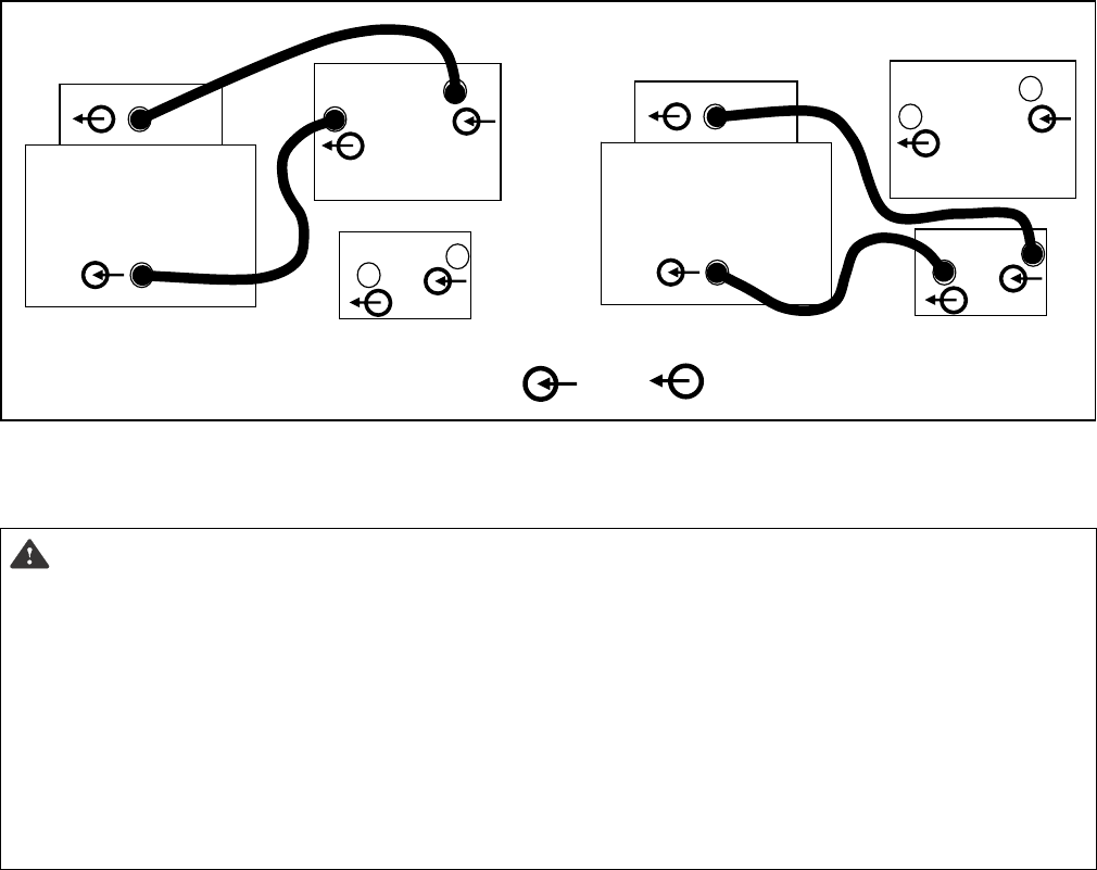
Figure 3-6. Connecting X10 Biodecontamination Unit and AR60 Aerator to Enclosure
3.2.3 Cycle Completion
The following information is intended to enable a Trained and Certified
Applicator to properly disconnect a X10 Biodecontamination Unit from
an Enclosure (refer to
SECTION 2.1, TERMS AND DEFINITIONS
) after
Biodecontamination Cycle completion:
1. After CYCLE COMPLETE, Enclosure may be entered per FMP.
2. Remove and properly discard of used desiccant cartridge and
Sterilant Cup from Biodecontamination Unit.
3. Disconnect hoses, move Biodecontamination Unit from
Enclosure.
NOTE: Do not transport Biodecontamination Unit with Sterilant
Cup in the Unit.
4. Remove Sash Support and Exhaust Plenum Adapter from
Enclosure.
5. Return Enclosure to operational status per FMP.
Enclosure
VHPX10
VHPAR60
Enclosure
VHPX10
VHPAR60
Biodecontamination Unit Connected to Enclosure
InletKEY: Outlet
Aerator Connected to Enclosure
DANGER – CHEMICAL INJURY HAZARD:
• Any visible liquids in the Enclosure (refer to
SECTION 2, TERMS AND DEFINITIONS
) must be treated as
concentrated hydrogen peroxide. Always test residual liquids, using a Liquid Hydrogen Peroxide
test strip (follow manufacturer's instructions), before diluting and wiping up. Observe all hydrogen
peroxide handling precautions presented in the Vaprox 59 Hydrogen Peroxide Sterilant SDS,
product label and package insert.
• At the end of the Aeration phase, use a low level hydrogen peroxide monitor to check and
periodically monitor the hydrogen peroxide vapor concentration within the Enclosure (refer to
SECTION 2, TERMS AND DEFINITIONS). The hydrogen peroxide vapor concentration should be at or
below established levels before the Enclosure is accessed by Trained and Certified Applicators.
The Vaprox 59 Hydrogen Peroxide Sterilant label and package insert contain required hydrogen
peroxide limits for re-entry and releasing of the Enclosure after Biodecontamination
4-1
Troubleshooting Operator Manual 10087252
4.1 Troubleshooting The VHP X10™ Biodecontamination Unit alerts the Trained and
Certified Applicator of various alarm/abort situations. Alarms occur
as a result of component failures, utility failures, unexpected
measurements from sensors or as a warning indication that
Applicator intervention is necessary (see Table 4-1 and Table 4-2).
Refer to Troubleshooting Guide (Table 4-3) for description of Alarm
Message Displays.
If a situation occurs that is not described in this manual, please call
STERIS Life Sciences. Trained service personnel can promptly
restore this X10 Biodecontamination Unit to proper working order.
NOTE: Never permit unqualified persons to service this
Biodecontamination Unit.
IMPORTANT: A listing of the
SAFETY PRECAUTIONS
to be observed when operating and servicing this
equipment and/or handling Vaprox 59 Hydrogen Peroxide Sterilant can be found in
SECTION 1
of this
manual. Do not operate or service the equipment or handle the Sterilant until you have been trained
and certified on this information as well as the information on the Vaprox 59 Hydrogen Peroxide
Sterilant product label and package insert.
DANGER – PERSONAL
INJURY, CONTAMINATED
ENCLOSURE AND/OR
EQUIPMENT DAMAGE
HAZARD: No one may enter a
sealed Enclosure during or
after an aborted cycle without
SCBA and appropriate PPE
(refer to Sterilant SDS for
PPE) if Sterilant levels within
the treated Enclosure are
above one PPM. Refer to
Sterilant label and package
insert for instructions.
WARNING – PERSONAL
INJURY AND/OR EQUIPMENT
DAMAGE HAZARD: Integrated
(temperature and humidity)
sensors are fragile. Do not
bang, twist or crush.
Biodecontamination Unit does
not operate properly with a
damaged sensor.
Table 4-1. Alarm/Abort Actions
Phase at Alarm-Abort Action Following
Alarm-Abort
Before start of Sterilant
Injection phase (before
Condition/Biodecontamination)
Advance to Cycle Complete
During Sterilant injection
(Condition/Biodecontamination)
Advance to Aeration
Table 4-2. Power Interruption/Power-Up Actions
Active Cycle Phase Action Upon Power
Return
Heat Cabinet Abort Cycle
Dehumidify Abort Cycle
Re-Heat Cabinet Abort Cycle
Heater Cap Warm-Up Abort Cycle
Condition Aeration
Biodecontamination Aeration
Aeration Restart Aeration
Cycle Complete Return to Cycle Complete
TROUBLESHOOTING 4

4-2
10087252 Operator Manual Troubleshooting
roup
Table 4-3. Troubleshooting Guide
Alarm Message
Display Description Possible Causes and / or
Corrections
1. Power Lost Occurs after the X10 BU has
experienced a loss of power
• System Initiated: NA
2. Door Open Occurs when the safety interlock
key is not inserted in the safety
interlock switch
• Door not completely closed at beginning of
cycle – Close Door
• Safety interlock switch failure or wiring
disconnected/shorted.
• Contact STERIS.
3. Door Interlock Fail Occurs at any time during a cycle
and after the dehumidify phase,
the safety door interlock coil
remains energized
• Safety interlock switch failure or wiring
disconnected/shorted.
• Contact STERIS.
4. Datalog Save Fail Occurs while attempting to save a
datalog file to a USB Flash
memory stick
• Verify that a USB Flash memory stick is
inserted in the USB port.
• Attempt the save operation while using a
different USB Flash memory stick.
5. Heater Cap RTD Fail Occurs when the heater cap RTD
(RTD1) temperature reading
indicates a break or short in the
wiring or the reading is at an
extreme high or low for 10 seconds
continuously
• Sensor failure or wiring disconnected/
shorted.
• Analog channel failure.
• Contact STERIS.
6. Htr Cp Too Long Heat Occurs during the heating (heater
cap) phase (prior to Condition or
Biodecontamination), the heater
cap temperature fails to reach the
setpoint temperature within
15 minutes
• Improper in-cycle heater cap temperature
setpoint.
• RTD1/Control board/Wiring failure.
• RTD1 failure.
• AC Control Board/Solid State relay (SSR2)
failure.
• Contact STERIS.
7. Heater Cap Temp
Dev
Occurs during the Condition or
Biodecontamination phase, the heater
cap RTD1 temperature reading is 86°F
(30°C) above or below the
programmed setpoint temperature for
two seconds continuously
• Pre-heater temperature too low.
• RTD1/Control Board/Wiring failure.
• Improper in-cycle heater cap temperature
setpoint.
• Contact STERIS.
8. Heater Cap
Overtemp
Occurs at any time, the heater cap
over-temperature switch (SW2) has
tripped
• RTD1 failure.
• Solid State relay (SSR2) failure.
• RTD1/Control Board/Wiring failure when
heater cap is cool.
• Contact STERIS.

4-3
Troubleshooting Operator Manual 10087252
9. Cabinet Temp RTD
Fail
Occurs at any time, the Airflow
RTD (RTD2) temperature reading
indicates a break or short in the
wiring or the reading is at an
extreme high or low, for
10 seconds continuously
• Sensor failure or wiring disconnected/
shorted: Check RTD2 connector and
connector on control board. Repair as
needed or replace RTD.
• Control Board failure: Replace control
board.
10. Cabinet Too Long
Heat
Occurs during the heating
(cabinet) phase (prior to Condition
or Biodecontamination), and after
15 minutes of operation, the
Cabinet Temperature does not
increase 0.1°C over a 5 minute
period
• Improper cabinet heater temperature
setpoint: Verify temperature setpoint.
Setpoint should be approximately 31°C.
• RTD2/Control Board/Wiring failure: Verify
proper operation of cabinet heater control
circuit.
• RTD2 failure: Calibrate or replace.
• Solid State relay (SSR2) failure: Replace.
11. RH Sensor Failure Occurs at any time, the airflow RH
(RH1) reading indicates a break or
short in the wiring for 10 seconds
continuously
• Sensor failure or wiring disconnected/
shorted: Check the RH1 connector and
connector on the control board. Repair as
needed or replace RH probe or board.
• Control Board failure: Replace control
board.
12. Dehumidify Timeout Occurs during the dehumidify
phase, the RH sensor fails to reach
the setpoint within 80 minutes
• Desiccant is saturated: Replace desiccant.
• Blower failure: Verify movement of air. See
Alarm Message 14.
• RH Sensor/Control Board/Wiring failure:
Verify proper operation of RH control circuit.
• RH Sensor failure: Calibrate or replace.
• Enclosure too large for dryer type: Increase
dryer capacity.
13. Blower Airflow Dev Occurs during any cycle phase,
the cycle flow blower (MTR-1)
control output has exceeded its
upper or lower limit for two minutes
continuously
• Air inlet blocked: Verify proper air flow
through X10 unit.
• MTR-1/Control Board/wiring failure: Verify
proper operation of blower control circuit.
• Solid State Relay (SSR1) failure: Replace.
14. Circ Blower Failure Occurs during any cycle phase
where the circulation blower option
is ON and the blower does not run
• MTR-1/Control Board/wiring failure: Verify
proper operation of blower control circuit.
• Solid State Relay (SSR1) failure: Replace.
15. Operator Abort Occurs at any time, when the
Operator requests an abort during
a cycle
• Operator initiated: Not applicable
Table 4-3. Troubleshooting Guide (Cont’d)
Alarm Message
Display Description Possible Causes and / or
Corrections

4-4
10087252 Operator Manual Troubleshooting
16. External Aerator Fail Occurs when the External Aerator
option is ON and the External
Aerator input is open.
• Auxillary Aerator Unit unplugged from Unit:
Connect Auxillary Aerator Unit.
• External Aerator option inadvertently
selected: Deselect this option in the menu.
17. Sterilant Cup
Expired
Occurs during the reading of the
sterilant cup RFID tag, the sterilant
cup expiration date is past the
current calendar date
• Replace the sterilant cup with one that is
not expired.
• Check the sterilant cup's printed expiration
date.
• Check that the BU system date is correct.
18. Sterilant Cup Used Occurs during the reading of the
sterilant cup RFID tag, the sterilant
cup serial number matches a
previously used code
• Replace the sterilant cup with one that has
not been used.
19. Sterilant Cup Bad
SKU
Occurs during the reading of the
sterilant cup RFID tag, the sterilant
cup SKU code does not match the
BSC system SKU code
• Replace the sterilant cup with one that has
the correct SKU.
• Check the sterilant cup's printed SKU code.
20. Sterilant Cup Bad
Wrt
Occurs during the condition
phase, the writing of the sterilant
cup RFID tag, and subsequent
verification reading, the RFID tag's
serial number does not contain the
used cup code
• Manually mark the cup as used.
• Verify the proper operation of the RFID
Reader/Writer.
21. RH Sensor Not
Calib
Appears at any time the RH
Sensor's Relative Humidity input is
identified as not calibrated
• System initiated: Not applicable.
22. RH RTD Not Calib Appears at any time the RH
Sensor's RTD input is identified as
not calibrated
• System initiated: Not applicable.
23. Machine Calib Due Occurs any time calibration is due
for the BSC Unit analog inputs or
outputs
• System initiated: Not applicable.
24. Drum Assembly
Index Fail
Occurs at any time the drum
assembly does not encounter one
of the three indexer sensors
• Check sensors on the drum position board.
• Check the drum indexing motor (MTR-2).
• Verify proper torque on rear drum assembly
retaining bolt.
25. Control Board Fail Occurs at any time a Control
Board fault is issued by the Control
Board
•TBD.
* STERIS Life Sciences
Table 4-3. Troubleshooting Guide (Cont’d)
Alarm Message
Display Description Possible Causes and / or
Corrections

5-1
Routine Maintenance Operator Manual 10087252
5.1 Read Before
Performing Routine
Maintenance
The routine maintenance procedures described in this section of the
manual should be performed whenever necessary. Any maintenance
procedures not included in this section should be performed only by
STERIS Life Sciences Service or STERIS-trained service personnel
fully acquainted with the equipment.
In addition to the routine maintenance described in this section,
regularly scheduled preventive maintenance is essential for safe and
reliable operation of the equipment. Annual maintenance agreements
are available to provide scheduled maintenance, adjustments and
replacement of worn parts performed by a qualified technician, to
help ensure peak equipment performance and help avoid
unscheduled downtime. Contact STERIS Life Sciences for details.
Maintain a record of all maintenance procedures performed on the
VHP X10™ Biodecontamination Unit. If a problem occurs, refer to
SECTION 4, TROUBLESHOOTING, or contact STERIS Life Sciences.
NOTE: Never permit unqualified persons to service this equipment.
WARNING – PERSONAL
INJURY AND/OR EQUIPMENT
DAMAGE HAZARD:
• Repairs and adjustments to
this equipment must be
made only by STERIS Life
Sciences or STERIS-trained
service personnel.
Maintenance performed by
unqualified personnel or
installation of unauthorized
parts could cause personal
injury, result in improper
equipment performance,
invalidate the warranty or
result in costly damage.
Contact STERIS Life
Sciences regarding service
options.
• Regularly scheduled
preventive maintenance is
required for safe and
reliable operation of this
equipment. Contact STERIS
Life Sciences to schedule
preventive maintenance.
ROUTINE MAINTENANCE 5

5-2
10087252 Operator Manual Routine Maintenance
5.2 Clean
Biodecontamination
Unit
STERIS Life Sciences recommends cleaning the outside surfaces of
the VHP X10 Biodecontamination Unit with a mild detergent solution
(such as Liqui-Jet™ 2 Instrument Detergent).
Clean the Biodecontamination Unit as follows:
1. Unplug unit.
2. Apply cleaning solution with a damp cloth, rubbing in back and
forth motion.
NOTE: Avoid getting solution into the controls. Wring out cloth
before wiping the control panel.
3. Rinse cloth and wipe off any detergent residue.
4. Dry surfaces with clean, lint-free cloth.
NOTE: Should it become necessary to sterilize or disinfect the
outside plastic VHP X10 Biodecontamination Unit surfaces before
entering an Enclosure, STERIS Life Sciences recommends Spor-
Klenz® Ready-To-Use Cold Sterilant. This sterilant is a liquid
sporicide specifically formulated for sterilization and disinfection of
hard surfaces.
CAUTION – POSSIBLE
EQUIPMENT DAMAGE: Use
nonabrasive cleaners when
cleaning Biodecontamination
Unit. If you need technical
assistance or additional
instructions, call STERIS
Life
Sciences
.
• Follow all directions on
container.
• Do not use abrasive
cleaners on plastic
surfaces.
• Avoid detergents with
bases, aromatics, ketones,
esters and chlorinated
hydrocarbons.
• Avoid contacting plastic
surfaces with greases and
oils.

5-3
Routine Maintenance Operator Manual 10087252
5.3 Clean Hoses NOTE: Condensation inside the hoses must be assumed to be
concentrated hydrogen peroxide (H2O2). Review the DANGERS,
WARNINGS and CAUTIONS located below and in SECTION 1,
SAFETY PRECAUTIONS, of this manual before handling the hoses.
Also, read and comply with the Safety Precautions outlined on the
Vaprox® 59 Hydrogen Peroxide Sterilant MSDS and the Vaprox 59
Hydrogen Peroxide Sterilant product label and package insert.
The Sterilant delivery hoses must be cleaned periodically to remove
dust and other debris from the interior surfaces. Clean the hoses
annually, or whenever the interior of the hoses becomes soiled or
dusty.
Clean hose interiors as follows:
1. Put on PPE (refer to Vaprox 59 Hydrogen Peroxide Sterilant SDS
for PPE).
DANGER – FIRE AND EXPLOSION HAZARD: Liquid hydrogen peroxide is a strong oxidant and
poses a FIRE, EXPLOSION OR CONTAINER RUPTURE HAZARD. Avoid excessive heat,
contamination or contact with combustible materials. Clothing, shoes or other combustible
materials that have come in contact with hydrogen peroxide must be immediately and thoroughly
washed with water. Discard shoes contaminated with Vaprox sterilant in a fireproof container. If
Vaprox 59
Hydrogen Peroxide Sterilant is allowed to dry in the materials, a fire may result. IN CASE
OF FIRE, use water only. CONTAIN SPILLS and dilute with water (at least 20 parts water to one part
H2O2). After diluting the spill, sodium metabisulfide or sodium sulfite (1.9 lb of SO2 equivalent per
500 mL of H2O2) may be used to destroy the peroxide. SEE MSDS FOR ADDITIONAL INFORMATION.
EFFECTS MAY BE DELAYED.
DANGER – SLIPPING HAZARD: Water or hydrogen peroxide spilled on the floor presents a slipping
hazard – promptly clean up the spill. If in doubt whether the liquid is water or hydrogen peroxide,
test the liquid using a Liquid Hydrogen Peroxide Test Strip (follow manufacturer's instructions),
before wiping up. If the liquid is hydrogen peroxide, contain the spill and dilute with water (at least
20 parts water to one part H2O2) prior to wiping up. Observe all hydrogen peroxide handling
precautions. Refer to the
Vaprox 59
Hydrogen Peroxide Sterilant SDS for spill containment and
cleanup.
DANGER – CHEMICAL INJURY HAZARD:
• CORROSIVE. Causes irreversible eye damage or skin burns. May be fatal if inhaled. Harmful if
swallowed or absorbed through the skin. Do not get in eyes, on skin or on clothing. Do not
breathe spray mist. Prolonged or frequently repeated skin contact may cause allergic reaction in
some individuals. User should wash hands before eating, drinking, chewing gum, using tobacco
or using the toilet. User should remove contaminated clothing and wash before reuse.
Applicators and all other handlers must wear PPE (refer to
Vaprox 59
Hydrogen Peroxide Sterilant
SDS for PPE). See Vaprox Hydrogen Peroxide Sterilant or Vaprox 59 Hydrogen Peroxide Sterilant
product label and package insert for additional handling information.
• When handling the Biodecontamination System hoses, wear appropriate Personal Protective
Equipment (refer to
Vaprox 59
Hydrogen Peroxide Sterilant SDS for PPE). Any visible liquid in the
hoses must be treated as concentrated hydrogen peroxide and all hydrogen peroxide handling
precautions must be observed.
• When handling hydrogen peroxide, wear appropriate PPE (refer to
Vaprox 59
Hydrogen Peroxide
Sterilant SDS for PPE) and observe all Safety Precautions. See
Vaprox 59
Hydrogen Peroxide
Sterilant MSDS, product label and package insert for additional handling information.

5-4
10087252 Operator Manual Routine Maintenance
2. Remove or disconnect hoses from Enclosure (refer to
SECTION 2.1,
TERMS AND DEFINITIONS
) and/or Biodecontamination Unit.
NOTE: Sterilant delivery hoses should not be left lying around
where they can be contaminated with dust or other particles which
may catalyze the decomposition of the Sterilant. Hoses should be
disconnected from the VHP X10 Biodecontamination Unit and
stored when not connected to an Enclosure.
3. Submerge hoses in a clean sink or tub filled with water containing
a mild detergent.
4. Soak hoses for 30 minutes, then drain the sink or tub.
5. Thoroughly rinse hoses with distilled water.
6. Dry hoses by blowing oil-free, filtered, compressed air through
them, or allow hoses to air dry.
7. Return hoses to their original position when dry.
5.4 Cleaning Touch
Screen
The VHP X10 Biodecontamination Unit is controlled by a PLC. Clean
the touch screen at regular intervals (at least once a week) as follows:
1. Ensure Biodecontamination Unit power is OFF.
2. Using water with detergent, screen cleaning agent or alcohol
(Ethanol), dampen a clean cloth. Do NOT spray fluid directly on
screen.
3. Gently wipe screen.
4. Dry with clean, lint-free cloth.
5.5 Replacement Parts
and Supplies
Use only STERIS-authorized parts on this equipment. Use of
unauthorized parts will void the warranty.
5.5.1 Ordering Information To order replacement parts and/or supply products, proceed as
follows:
1. Include the part number and description as listed in
SECTION 5.5.2, SUPPLY PRODUCTS and SECTION 5.5.3,
RECOMMENDED SPARE PARTS.
2. Include the model and serial numbers of your equipment on your
order.
3. Send your order directly to the STERIS Life Sciences
Representative serving your area.
Contact STERIS Life Sciences* if you need parts that are not listed in
this manual.
*1 (800) 440-9009 or www.sterislifesciences.com.
WARNING – PERSONAL
INJURY AND/OR EQUIPMENT
DAMAGE HAZARD: Repairs
and adjustments to this
equipment must be made only
by STERIS Life Sciences or
STERIS-trained service
personnel. Maintenance
performed by unqualified
personnel or installation of
unauthorized parts could
cause personal injury, result
in improper equipment
performance, invalidate the
warranty or result in costly
damage. Contact STERIS Life
Sciences regarding service
options.
5-5
Routine Maintenance Operator Manual 10087252
5.5.2 Supply Products NOTE: Use only STERIS U.S. EPA-registered Vaprox 59 Hydrogen
Peroxide Sterilant in STERIS Containers. Vaprox Containers contain
high purity 59% hydrogen peroxide and are filled under controlled
conditions to ensure effectiveness through the expiration date stamped
on the label. Federal law requires that the sterilant be registered with
the U.S. EPA. Use of unregistered sterilant is prohibited and a violation
of Federal Insecticide, Fungicide and Rodenticide Act (FIFRA) federal
law and will void the warranty.
5.5.3 Recommended Spare
Parts
The parts listed in this section are those that are necessary to repair
the VHP X10 Biodecontamination Unit in most instances.
DANGER – PERSONAL
INJURY, CONTAMINATED
ENCLOSURE AND/OR
EQUIPMENT DAMAGE
HAZARD: Use only
Vaprox 59
Hydrogen Peroxide Sterilant
Containers, containing
STERIS-registered hydrogen
peroxide which has been
specially formulated, tested
and approved for use in this
X10 Biodecontamination Unit.
Vaprox 59
Hydrogen Peroxide
Sterilant has been registered
by STERIS in accordance with
U.S. Federal Regulations for
the specific uses described in
this manual. Use of other
materials and/or H
2
O
2
other
than
Vaprox 59
H
2
O
2
Sterilant
could impair equipment
operation, result in costly
repairs, result in an ineffective
Biodecontamination Cycle,
violate federal law and void the
equipment warranty.
Table 5-1. VHP X10 Biodecontamination Unit
Selected Supply Products
Description Part
Number
Vaprox 59 Hydrogen Peroxide Sterilant
(EPA Reg. No. 1043-123); 4 x 70 mL
PB034US
VHP X10 Desiccant Cartridge) 10032310
Spor-Klenz Ready-To-Use Cold Sterilant
(1 qt. - 4 per case)
6525M2
Liqui-Jet 2 Instrument Detergent (1 gal) 103708
Table 5-2. Recommended Spare Parts
Description Part Number Quantity
BATTERY, Main Control Board, 3 V (CR2477) 2
CORD, Power, 230 Vac 10035152 1
CORD, Power, 120 Vac 10035151 1
CUP, Vaprox 59 Hydrogen Peroxide Sterilant (EPA Reg. No. 1043-123, 70 mL) PB034 1
DESICCANT TBD 1
FERRULE, Flangeless Tubing P387349-031 10
FILTER, Injection 10015443 2
FUSE, Blower, 4 A 10037461 2
FUSE, Blower, 4 A ((For 120 Vac Unit) 10017002 2
FUSE, Blower, 2 A (For 230 Vac Unit) 10034820 2
FUSE, Heater, 10 A (For 120 Vac Unit) 10017003 2
5-6
10087252 Operator Manual Routine Maintenance
5.6 Associated
Publications
Publications listed in this section are those associated with the use
and maintenance of this VHP X10 Biodecontamination Unit.
When ordering, please include the part number (if applicable),
description and quantity of each publication requested. Order directly
from STERIS Life Sciences Representative.
FUSE, Heater, 5 A (For 230 Vac Unit) 10017003 2
HARNESS, Amber Light 10020036 1
HOSE ASSEMBLY, 2” Cam Lever 10038131 5 ft
HOSE ASSEMBLY, 2” Cam Lever 10038130 10 ft
NUT, Tubing P387349-030 10
TUBE, Draw 10014998 1
Table 5-2. Recommended Spare Parts (Cont’d)
Description Part Number Quantity
Table 5-3. Associated Publications
Description Part Number
Tech Data Sheet SD997
Uncrating/Installation Instructions 10037273
Equipment Drawings 10105142
Maintenance Manual P764335-550
6-1
Supplemental Information Operator Manual10087252
6.1 Installation
Verification
An equipment drawing, showing all utility and space requirements, is
supplied when the X10
™
Biodecontamination Unit is ordered. Any
clearance space specified on the equipment drawing is necessary for
proper operation, maintenance and repair of the system components.
Uncrating/Installation Instructions were furnished with the X10
Biodecontamination Unit. If these documents are missing or misplaced,
contact STERIS Life Sciences, giving the serial, equipment and model
numbers of the unit. Replacement copies will be sent to you promptly.
NOTE: Do not use Unit in an area not compatible with oxidizers.
6.1.1 Installation
Checklist
After installing and connecting (refer to Figure 3-6) the X10
Biodecontamination Unit on a hard level surface according to the
instructions provided, complete the following checklist to ensure the
installation is complete and correct. Contact STERIS Life Sciences to
schedule a demonstration of proper equipment operation.
❑Unplug system before servicing.
❑Electric service to the system components must be as specified
on the component data plates and equipment drawings.
❑Electric service should be on a separate circuit, and not tied into
circuits containing large reactive loads (e.g., motors).
❑Electric service must provide a protective earth ground as
specified by the local codes for an industrial circuit.
❑Extension cord use is not recommended.
6.1.2 Pre-Operation
Checklist
Read all Safety Precautions in SECTION 1, SAFETY PRECAUTIONS,
before operating the equipment
. Then complete the following
checklist before operating the X10 Biodecontamination Unit.
Check that:
❑
The hoses (with appropriate connectors) properly connect the
Biodecontamination Unit to the Enclosure (refer to
SECTION 2.1,
TERMS AND DEFINITIONS
) or other system components as described
in
SECTION 3.2, OPERATION
.
❑A hydrogen peroxide detection monitor or vapor tubes must be
available to test for Enclosure (refer to SECTION 2.1, TERMS AND
DEFINITIONS) leakage.
REMEMBER – POSSIBLE
TIME DELAY: Insufficient
clearance space will make
repairs more difficult and
time-consuming. Refer to the
equipment drawing for
minimum clearance for
service/maintenance access
requirements.
DANGER – CHEMICAL INJURY HAZARD: When handling hydrogen peroxide, wear appropriate PPE
(refer to
Vaprox 59
Hydrogen Peroxide Sterilant SDS for PPE) and observe all Safety Precautions.
See
Vaprox 59
Hydrogen Peroxide Sterilant SDS, product label and package insert for additional
handling information.
WARNING – PERSONAL INJURY AND/OR EQUIPMENT DAMAGE HAZARD:
• Lifting the Biodecontamination Unit requires more than one person. The unit weighs
approximately 65 lb (30 kg).
• Park Biodecontamination Unit only on flat surfaces. The caster brakes are not designed to
maintain the unit stationary on inclined surfaces. In addition, various internal components are
designed for operation when unit is parked on a level, flat surface.
• Integrated (temperature and humidity) sensors are fragile. Do not bang, twist or crush.
Biodecontamination Unit does not operate properly with a damaged sensor.
SUPPLEMENTAL INFORMATION 6

6-2
10087252 Operator ManualSupplemental Information
❑
Biodecontamination Unit components are properly positioned in
relation to Enclosure (refer to
SECTION 2.1, TERMS AND DEFINITIONS
)
being processed, as described in
SECTION 3.2, OPERATION
.
❑The X10 Biodecontamination Unit components are properly
connected (refer to Figure 3-4 or Figure 3-6).
❑A Vaprox® 59 Hydrogen Peroxide Sterilant Cup is in place; if a
Cup is not in place or is empty, install a new Cup as described in
SECTION 6.6, STERILANT CUP INSTALLATION AND REMOVAL.
❑Desiccant cartridge assembly is properly inserted (see
SECTION 6.7, DESICCANT INSTALLATION AND REMOVAL).
6.2 Technical Data
6.2.1 Overall Size (W x H x D) 28 x 22 x 15" (711 x 559 x 381 mm)
6.2.2 Weight 68 lb (31 kg)
6.2.3 Electric Requirements 120 Vac, 50/60 Hz, 12 A, 1 Ph
230 Vac, 50/60 Hz, 7 A, 1 Ph
6.2.4 Environmental
Conditions
Temperature: 60 to 104°F (16 to 40°C)
Maximum Humidity: 70%
A-Weighted Sound Power Level: 73 dBA (mean) - 83 dBA (maximum);
use earplugs.
Pollution Degree: 2
Installation Category (Overvoltage Category): II
IP67 Rating Closed; IP20 Rating Open
IC Number: IC:11700A-VHPX10
IC Statement:
This device complies with Industry Canada license-exempt RSS
standard(s). Operation is subject to the following two conditions:
(1) this device may not cause interference, and (2) this device
must accept any interference received, including interference that
may cause undesired operation.
FCC Number: 2ABQIVHPX10.
FCC Statement:
This device complies with Part 15 of the FCC Rules. Operation is
subject to the following two conditions: (1) this device may not
cause harmful interference, and (2) this device must accept any
interference, including interference that may cause undesired
operation of the device.
NOTE: This equipment has been tested and found to comply with the
limits for a Class A digital device, pursuant to part 15 of the FCC Rules.
These limits are designed to provide reasonable protection against
harmful interference when the equipment is operated in a commercial
environment. This equipment generates, uses, and can radiate radio
frequency energy and, if not installed and used in accordance with the
instruction manual, may cause harmful interference to radio
communications. Operation of this equipment in a residential area is
likely to cause harmful interference in which case the user will be
required to correct interference at his own expense.
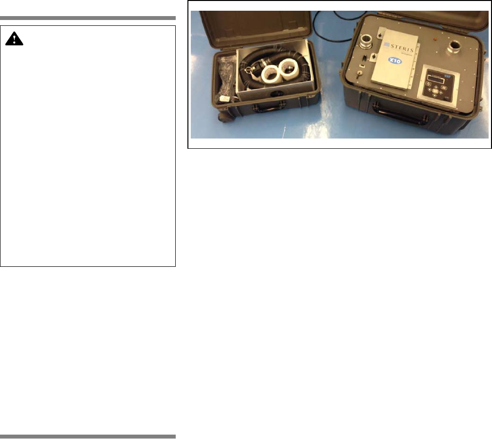
6-3
Supplemental Information Operator Manual10087252
6.3 Hydrogen Peroxide
Biodecontamination
Figure 6-1. X10 Biodecontamination Unit
The X10 Biodecontamination Unit (see Figure 6-1) provides a simple
and reliable method for Biodecontaminating pre-cleaned, dry sealable
Enclosures (refer to SECTION 2.1, TERMS AND DEFINITIONS).
Effective use of H2O2 vapor for Biodecontamination requires adequate
concentration and exposure time.
The X10 Biodecontamination Unit typically uses a closed loop process
(refer to SECTION 3, OPERATING INSTRUCTIONS) utilizing air as a carrier
to deliver Vaprox 59 Hydrogen Peroxide Sterilant vapor to the
exposed surfaces inside a pre-cleaned, dry, sealed Enclosure (refer
to SECTION 2.1, TERMS AND DEFINITIONS). This closed loop process
allows the Biodecontamination process to take place at atmospheric
conditions. Because Biodecontamination relies only on the contact of
Sterilant with exposed surfaces, the transfer of heat and moisture
required by steam processes is not necessary.
H2O2 vapor is continuously injected for the required exposure time to
achieve Biodecontamination. The Sterilant evacuated from the
Enclosure in a closed loop operation is catalytically converted into
water vapor and oxygen. .
6.4 Biodecontamination
Cycle
The properly installed X10 Biodecontamination Unit outside the
Enclosure (refer to
SECTION 2.1, TERMS AND DEFINITIONS
) uses STERIS’s
VHP
®
process technology. This process uses hydrogen peroxide vapor
as a broad-spectrum antimicrobial without condensation of active
ingredient onto surfaces. This non-condensation feature provides
additional benefit of a wide range of material compatibility.
In practice, an aqueous solution of 59% (Vaprox 59 Hydrogen Peroxide
Sterilant) hydrogen peroxide vapor is atomized and a high velocity air
stream disperses it throughout Enclosure. Relative humidity and
temperature sensor measurements ensure the vapor does not condense
on internal Enclosure surfaces.
NOTE: Refer to the Vaprox 59 Hydrogen Peroxide Sterilant package
label for additional information and Application instructions.
DANGER – PERSONAL INJURY,
CONTAMINATED ENCLOSURE
AND/OR EQUIPMENT DAMAGE
HAZARD: Use only
Vaprox 59
Hydrogen Peroxide Sterilant Cups,
containing STERIS-registered
hydrogen peroxide which has
been specially formulated, tested
and approved for use in this X10
Biodecontamination Unit. V
aprox
59
Hydrogen Peroxide Sterilant
has been registered by STERIS in
accordance with U.S. Federal
Regulations for the specific uses
described in this manual. Use of
other materials and/or H
2
O
2
other
than V
aprox 59
H
2
O
2
could impair
equipment operation, result in
costly repairs, result in an
ineffective Biodecontamination
Cycle, violate federal law and void
the equipment warranty.
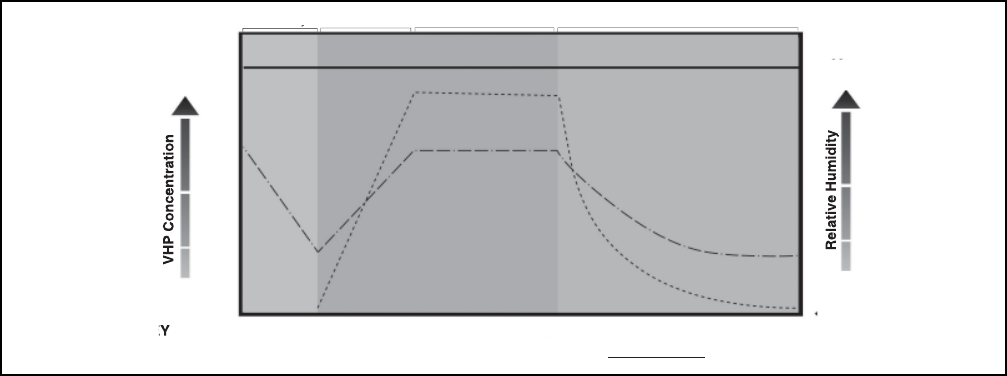
6-4
10087252 Operator ManualSupplemental Information
The Biodecontamination Cycle (see Figure 6-2) proceeds as follows:
1. Biodecontamination Unit display prompts Trained and Certified
Applicator to insert Vaprox 59 Hydrogen Peroxide Sterilant Cup and
desiccant cartridge (see
SECTION 6.6, STERILANT CUP INSTALLATION
AND REMOVAL
and
SECTION 6.7, DESICCANT INSTALLATION AND
REMOVAL
).
2. Display prompts user to press START.
NOTE: After starting the cycle, the Trained and Certified Applicator
has time to safely finalize any sealing per FMP prior to Condition
and Biodecontamination phases.
3. Biodecontamination Unit performs a system check on Sterilant
Cup.
4. Upon successful check, Biodecontamination Unit begins Pre-Heat
Cabinet phase.
5. After pre-heating cabinet to 88°F (31°C), Dehumidification phase
starts and air circulates through desiccant to dehumidify
Enclosure to 15% RH.
NOTE: During this time the liquid Sterilant is primed into the
injection lines (approximately two minutes for priming).
6. After 15% RH setpoint is reached, Enclosure is heated to 88°F
(31°C).
7. Once setpoint is reached, heater cap is heated to set value.
8. Condition phase (Sterilant injection) begins. Biodecontamination
Unit generates hydrogen peroxide vapor and circulates Sterilant
throughout Enclosure at set injection rate to build concentration to
> 400 PPM.
9. Biodecontamination phase follows for preset time.
Biodecontamination Unit continues to circulate hydrogen peroxide
vapor at a lower injection rate to achieve desired bioburden
targets.
Figure 6-2. Typical Biodecontamination Cycle
KE
- - - - - - - - - - - Gas Concentration .
_
.
_
.
_
.
_
.
_
Relative Humidity Condensation Point
Les
s
Dehumidif
y
C
ondition
B
i
od
eco
nt
a
min
a
ti
on
A
erat
i
on
Mo
r
e
Less
More
VHP Concentration Relative Humidity Condensation Point

6-5
Supplemental Information Operator Manual10087252
10. At completion of Biodecontamination phase, Biodecontamination
Unit enters a Hold phase to recirculate Sterilant vapor for set time
(no injection or heat).
11. Injection lines are purged of any liquid back into Vaprox 59
Hydrogen Peroxide Sterilant Cup (approximately three minutes for
purging).
12. At Hold phase completion, Biodecontamination Unit advances to
Aeration phase for pre-determined time.
13. Air passes through catalyst until Sterilant concentration is reduced
to 1 ppm.
14. Cycle Complete phase begins. Biodecontamination Unit turns
blower OFF and saves cycle data to USB.
6.5 Hydrogen Peroxide
Handling Precautions
Certain precautions
must
be observed when handling hydrogen
peroxide (H
2
O
2
).
Review the Safety Precautions located in SECTION 1
of this manual before handling the Vaprox 59 Hydrogen Peroxide
Sterilant Cups
. Also, read, comply with and save the Sterilant SDS and
Vaprox 59 Hydrogen Peroxide Sterilant Cups label and package insert.
DANGER – PERSONAL INJURY, CONTAMINATED ENCLOSURE AND/OR EQUIPMENT DAMAGE
HAZARD:
• Use only
Vaprox 59
Hydrogen Peroxide Sterilant Containers, containing STERIS-registered
hydrogen peroxide which has been specially formulated, tested and approved for use in this X10
Biodecontamination Unit. V
aprox 59
Hydrogen Peroxide Sterilant has been registered by STERIS
in accordance with U.S. Federal Regulations for the specific uses described in this manual. Use
of other materials and/or H2O2 other than V
aprox 59
Hydrogen Peroxide Sterilant could impair
equipment operation, result in costly repairs, result in an ineffective Biodecontamination Cycle,
violate federal law and void the equipment warranty.
• Before using V
aprox 59
Hydrogen Peroxide Sterilant Cup, check the expiration date. Do not use
Sterilant if it is beyond its expiration date, or if it will not be fully used before its expiration date.
• Before disposing of a V
aprox
59 Hydrogen Peroxide Sterilant
Cup, empty all remaining Cup
contents into a sink with running water (at least 20 parts water to one part Vaprox H2O2), then
carefully triple rinse the Cup with tap water.
DANGER – CHEMICAL INJURY HAZARD:
• CORROSIVE. Causes irreversible eye damage or skin burns. May be fatal if inhaled. Harmful if
swallowed or absorbed through the skin. Do not get in eyes, on skin or on clothing. Do not breathe
spray mist. Prolonged or frequently repeated skin contact may cause allergic reaction in some
individuals. User should wash hands before eating, drinking, chewing gum, using tobacco or
using the toilet. User should remove contaminated clothing and wash before reuse. Applicators
and all other handlers must wear PPE (refer to V
aprox 59
Hydrogen Peroxide Sterilant SDS for
PPE). See V
aprox 59
Hydrogen Peroxide Sterilant product label and package insert for additional
handling information.
• When handling the Biodecontamination System hoses, wear appropriate PPE (refer to V
aprox 59
Hydrogen Peroxide Sterilant SDS for PPE). Any visible liquid in the hoses must be treated as
concentrated hydrogen peroxide and all hydrogen peroxide handling precautions must be
observed.
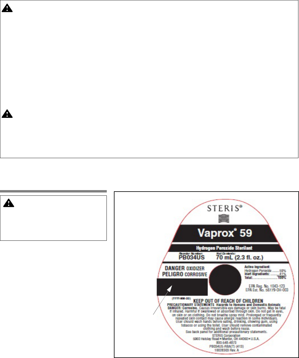
6-6
10087252 Operator ManualSupplemental Information
6.6 Sterilant Cup
Installation and
Removal
Review SECTION 6.5, HYDROGEN PEROXIDE HANDLING PRECAUTIONS,
before proceeding. The X10 Biodecontamination Unit uses Vaprox 59
Hydrogen Peroxide Sterilant in Cups (see FIGURE 6-3).
Figure 6-3. Typical Sterilant Cup
DANGER – FIRE AND EXPLOSION HAZARD:
• Liquid hydrogen peroxide is a strong oxidant and poses a FIRE, EXPLOSION OR CONTAINER
RUPTURE HAZARD. Avoid excessive heat, contamination or contact with combustible materials.
Clothing, shoes or other combustible materials that have come in contact with hydrogen
peroxide must be immediately and thoroughly washed with water. Discard shoes contaminated
with V
aprox 59
Hydrogen Peroxide Sterilant in a fireproof container. If Vaprox Sterilant is allowed
to dry in the materials, a fire may result. IN CASE OF FIRE, use water only. CONTAIN SPILLS and
dilute with water (at least 20 parts water to one part H2O2). After diluting the spill, sodium
metabisulfide or sodium sulfite (1.9 lb of SO2 equivalent per 500 mL of H2O2) may be used to
destroy the peroxide. SEE SAFETY DATA SHEET (SDS) FOR ADDITIONAL INFORMATION.
EFFECTS MAY BE DELAYED.
• Verify all materials coming in contact with hydrogen peroxide, especially the concentrated liquid,
are compatible with oxidizers. Contact STERIS Life Sciences or the material manufacturer for
information on material compatibility.
DANGER – SLIPPING HAZARD: Water or hydrogen peroxide spilled on the floor presents a slipping
hazard – promptly clean up the spill. If in doubt whether the liquid is water or hydrogen peroxide,
test the liquid using a Liquid Hydrogen Peroxide Test Strip (follow manufacturer's instructions),
before wiping up. If the liquid is hydrogen peroxide, contain the spill and dilute with water (at least
20 parts water to one part H2O2) prior to wiping up. Observe all hydrogen peroxide handling
precautions. Refer to the V
aprox 59
Hydrogen Peroxide Sterilant SDS for spill containment and
cleanup.
DANGER – PERSONAL INJURY,
CONTAMINATED ENCLOSURE
AND/OR EQUIPMENT DAMAGE
HAZARD: Before starting a
cycle, check Sterilant to ensure
it is not expired.
Data Matrix Code,
Lot Number,
Expiration Date
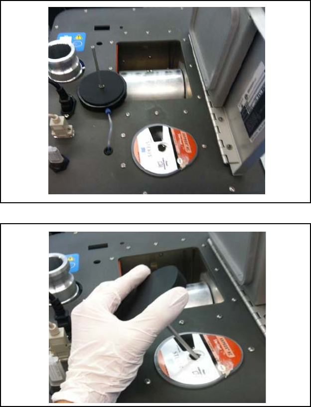
6-7
Supplemental Information Operator Manual10087252
6.6.1 Cup Installation Install Vaprox 59 Hydrogen Peroxide Sterilant Cup (see FIGURE 6-3) as
follows:
1. Wearing proper PPE, unpack desiccant cartridge and Vaprox 59
Sterilant Cup from packaging (refer to FIGURE 3-5).
2. Check Cup expiration date. Do not use Cup if beyond expiration
date listed on label (Figure 6-3).
3. Turn Biodecontamination Unit power ON, open supply door.
4. Gently grasp Cup and place in Biodecontamination Unit (see
Figure 6-4).
5. Carefully insert Cup draw tube into Cup (see Figure 6-5).
6. Close supply door and lock.
Figure 6-4. Sterilant Cup in Biodecontamination Unit (Typical)
Figure 6-5. Carefully Insert Draw Tube (Typical)
6.6.2 Cup Removal
When the Cycle is complete or if the X10 Biodecontamination Unit is to
be transported, the Cup must be removed. Proceed as follows:
1. Put on PPE (refer to Vaprox 59 Hydrogen Peroxide Sterilant SDS
for PPE).

6-8
10087252 Operator ManualSupplemental Information
2. Gently grasp Cup and draw tube with both hands. Carefully lift
Cup and draw tube from Biodecontamination Unit.
3. Dispose of Sterilant as directed in next section.
NOTE: For Cups, note the following:
1) If Cup in the Biodecontamination Unit is past the expiration date,
remove the Cup, dispose of contents as instructed in the next
Section (
SECTION 6.6.3, DISPOSAL OF STERILANT FROM CUP
).
2) Before transporting the Biodecontamination Unit, the Sterilant
Cup must be removed from Biodecontamination Unit.
6.6.3 Disposal of Sterilant
From Cup
If the Cup is empty, does not contain enough H2O2 for any further
Biodecontamination Cycles or the Biodecontamination Unit needs
transported, proceed as follows:
1. Put on PPE (refer to Vaprox 59 Hydrogen Peroxide Sterilant SDS
for PPE). Refer also to Vaprox 59 Hydrogen Peroxide Sterilant
label or package insert.
2. Empty all remaining Cup contents into a sink with running water
(at least 20 parts water to one part H2O2).
3. When Cup is empty, carefully and thoroughly triple rinse Cup with
tap water before disposal.
4. Properly dispose of empty Cup.
5. Rinse draw tube with water and set safely aside.
6.7 Desiccant
Installation and
Removal
The X10 Biodecontamination Unit uses desiccant cartridges to
convert the Sterilant into water vapor and oxygen. Install and remove
desiccant cartridge as follows:
1. If not already unpacked, wearing proper PPE, unpack desiccant
cartridge (see Figure 6-6) and Vaprox 59 Sterilant Cup from
packaging (refer to Figure 3-5).
2. Turn Biodecontamination Unit power ON, open supply door by
turning fastening screws (quarter turn).
3. Lift latch on desiccant door and place desiccant cartridge inside
(see Figure 6-7).
Figure 6-6. Desiccant Cartridge (Typical)
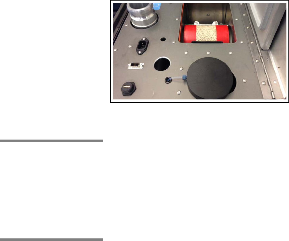
6-9
Supplemental Information Operator Manual10087252
Figure 6-7. Place Desiccant Cartridge in
Biodecontamination Unit
6.8 Sterilant
Container Storage
Vaprox 59 Hydrogen Peroxide Sterilant Cups are warranted through
the expiration date (see Figure 6-3) when the following storage
practices are followed:
• Store Cups in an upright (vertical) position.
• Store Containers at room temperature, not to exceed 77°F
(25°C). DO NOT FREEZE.
Shelf life of UNOPENED Vaprox 59 Hydrogen Peroxide Sterilant Cup
is one year.
Shelf life of OPENED Cup installed in the X10 Biodecontamination Unit
is 45 days. However, Cup must not remain in Biodecontamination Unit
when being transported.
6.9 General
Component
Identification
The X10 Biodecontamination Unit is designed for mobile
Biodecontamination of clean, dry, sealed Enclosures (refer to
SECTION 2.1, TERMS AND DEFINITIONS) of three, four, five and six foot
widths with corresponding internal volumes from 15.6 - 31.2 ft3 (.44 -
.88 m3) using STERIS’s patented VHP® Process Technology and using
Vaprox 59 Hydrogen Peroxide Sterilant.
NOTE: The X10 Biodecontamination Unit is to be used by Trained and
Certified Applicators who have successfully completed both the
STERIS Training and Certification Course for Applicators of Vaprox
Hydrogen Peroxide Sterilant and the X10 Biodecontamination Unit
Operator Course. Certification must be active and in force for all
Applicators of Vaprox 59 Hydrogen Peroxide Sterilant.
Before operating the X10 Biodecontamination Unit, become familiar
with the location and function of all major components and controls
presented in this section (see FIGURE 6-8). Refer to SECTION 2.1,
TERMS AND DEFINITIONS.
1. Power Cord – Connects Biodecontamination Unit to Facility
power.
2. Desiccant Cartridge – Converts Sterilant into water vapor and
oxygen.
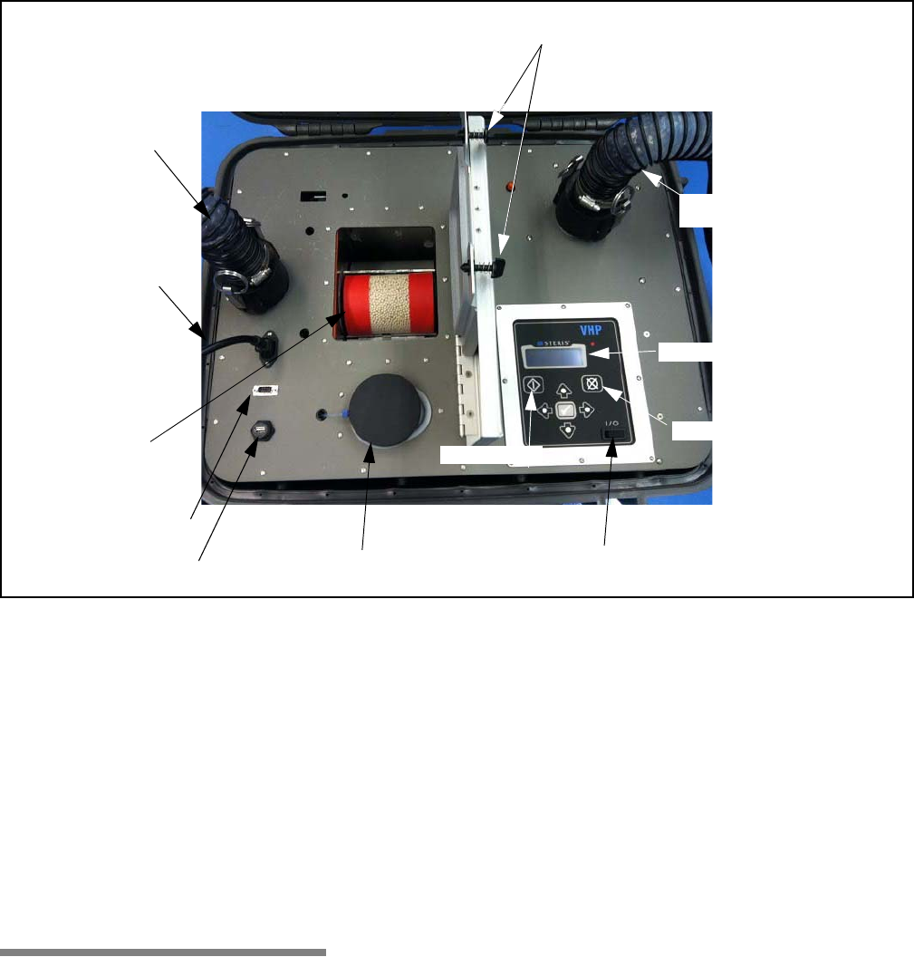
6-10
10087252 Operator ManualSupplemental Information
Figure 6-8. Component Identification
3. Cup Draw Tube – Draws Sterilant from Sterilant Cup.
4. Cup – Disposable Cup supplies Vaprox 59 Hydrogen Peroxide
Sterilant.
5. USB Port – Biodecontamination Unit outputs cycle data in
encrypted format for data storage through this port.
6. ON/OFF Switch – Enables power to controller.
7. Start Touch Pad – When pressed, starts cycle.
8. Abort Touch Pad - When pressed, aborts cycle.
9. Operation Screen – Can contain up to four lines of Operational
text to enable operator to communicate with controller.
6.10 Operation The following information is intended to enable a Trained and Certified
Applicator to properly use the Biodecontamination Unit to
Biodecontaminate an Enclosure (refer to SECTION 2.1, TERMS AND
DEFINITIONS):
The STERIS X10 Biodecontamination Unit is to be used by Trained
and Certified Applicators who have successfully completed both the
STERIS Training and Certification Course for applicators of Vaprox 59
Hydrogen Peroxide Sterilant and the STERIS X10 Biodecontamination
Unit Operator Course. Certification must be active and in force for all
Applicators of Vaprox 59 Hydrogen Peroxide Sterilant.
1. Ensure Biodecontamination Unit is properly attached to Enclosure
(refer to SECTION 3.2.1, ATTACH TO ENCLOSURE).
To Sash Plate
Assembly
To Exhaust Plenum
Adapter
Supply Door
Fastening Screws
Desiccant
Cartridge
Cup Draw Tube and Lid,
and Sterilant Cup
ON/OFF Switch
Start Touch Pad
Abort Touch Pad
Operation Screen
Power Cord
RS-232 Port
USB Port

6-11
Supplemental Information Operator Manual10087252
2. Per FMP*, make all necessary preparations to Enclosure. Verify
CIs and BIs are placed inside Enclosure as required.
*Guidance for developing a suitable Fumigation
Management Plan can be found in STERIS
publication (P129383-938) or searching EPA
website (epa.gov) for the key words ’Vaprox
Package Insert.’
3. Plug Biodecontamination Unit power cord into proper facility outlet
(120 Vac, 20A or 230 Vac, 10A; single source circuit).
4. Turn Biodecontamination Unit power ON using ON/OFF switch.
5. Control tells operator to install Cup as follows:
a. Open supply door by turning fastening screws (quarter turn).
When door is opened, control panel reads:
b. Wearing proper PPE, unpack desiccant cartridge and Vaprox
59 Sterilant Cup from packaging.
c. Ensure Sterilant Cup is not expired
d. Place Sterilant Cup and desiccant cartridge into unit.
NOTE: See SECTION 6.6, STERILANT CUP INSTALLATION AND
REMOVAL, and Section 6.7, Desiccant Installation and Removal,
for more information of desiccant cartridge and Sterilant Cup
insertion.
e. Carefully insert draw tube into Cup.
f. Close supply door and lock using fastening screws.
6. Once door is closed and locked, control displays:
7. After pressing START, control displays:
OPEN DOOR
INSERT VAPROX CUP
INSERT VAPROX CUP
AND DESICCANT
THEN CLOSE DOOR
PRESS <START>
TO CONTINUE
INSERT USB LOGGING
FLASH MEMORY DRIVE
OR PRESS <START>
TO CONTINUE

6-12
10087252 Operator ManualSupplemental Information
8. Biodecontamination Unit drum assembly rotates and heating of
Enclosure starts. Display shows:
9. When setpoint is reached, Dehumidify phase starts and display
shows:
10. When setpoint is reached, Warm-Up phase starts and display
shows:
11. When setpoint is reached, heater cap is heated and display
shows:
12. When setpoint is reached, Condition phase starts and display
shows:
3-4 FT CABINET CYCLE
PREHEATING CABINET
RH = XX.X% CT = XX.X °C
REM TIME xx:xx
3-4 FT CABINET CYCLE
DEHUMIDIFYING
RH = XX.X% CT = XX.X°C
REM TIME = XX:XX
3-4 FT CABINET CYCLE
WARMING UP CABINET
RH = XX.X% CT = XX.X°C
REM TIME = XX:XX
3-4 FT CABINET CYCLE
HEATING HEATER CAP
RH = XX.X% CT = XX.X°C
REM TIME = XX:XX
3-4 FT CABINET CYCLE
CONDITION
RH = XX.X% CT = XX.X°C
REM TIME = XX:XX

6-13
Supplemental Information Operator Manual10087252
13. When setpoint is reached, Decontamination phase starts and
display shows:
14. When setpoint is reached, Biodecontamination Unit enters a Hold
phase and display shows:
15. At completion of Hold phase, drum rotates, Aeration phase starts
and display shows:
16. If optional aeration is desired, proceed as follows:
a. Verify Biodecontamination Unit has reached Aeration phase of
Cycle. Press Cancel button.
b. Display asks, USE EXTERNAL AERATOR? Press Check
button.
c. Turn Biodecontamination Unit OFF.
d. Turn Enclosure fan OFF.
e. Position VHP AR60™ Aerator near Enclosure.
f. Disconnect Outlet and Inlet Hose Assemblies from
Biodecontamination Unit and connect to AR60 Aerator (refer
to FIGURE 3-6).
g. Plug AR60 Aerator into applicable wall outlet (120 or
230 Vac).
h. Turn AR60 Aerator ON by pressing power switch.
i. Turn Enclosure fan ON.
j. Allow AR60 Aerator to operate until H2O2 is reduced to a safe
level of less than or equal to 1 PPM.
3-4 FT CABINET CYCLE
DECONTAMINATION
RH = XX.X% CT = XX.X°C
REM TIME = XX:XX
3-4 FT CABINET CYCLE
HOLDING
RH = XX.X% CT = XX.X°C
REM TIME = XX:XX
3-4 FT CABINET CYCLE
MANDATORY AERATION
RH = XX.X% CT = XX.X°C
REM TIME = XX:XX

6-14
10087252 Operator ManualSupplemental Information
17. At completion of Aeration phase, drum rotates, door unlocks and
display shows:
18. Alarm sounds, press Check pushbutton to silence. Screen returns
to Home Screen and is ready for next cycle.
3-4 FT CABINET CYCLE
DECON. AND AERATION
COMPLETE-PRESS KEY