STI Engineering 9256TRX Frequency Hopping Spread Spectrum Transceiver User Manual
STI Engineering Pty Ltd Frequency Hopping Spread Spectrum Transceiver
UserManual.wiki
>
STI Engineering
>
9256TRX User Manual
>
User manual
Contents
1.
User manual
2.
Amended user manual
User manual
Navigation menu
Upload a User Manual
Namespaces
Wiki Guide
HTML
PDF
Info
Views
User Manual
Discussion / Help
Navigation


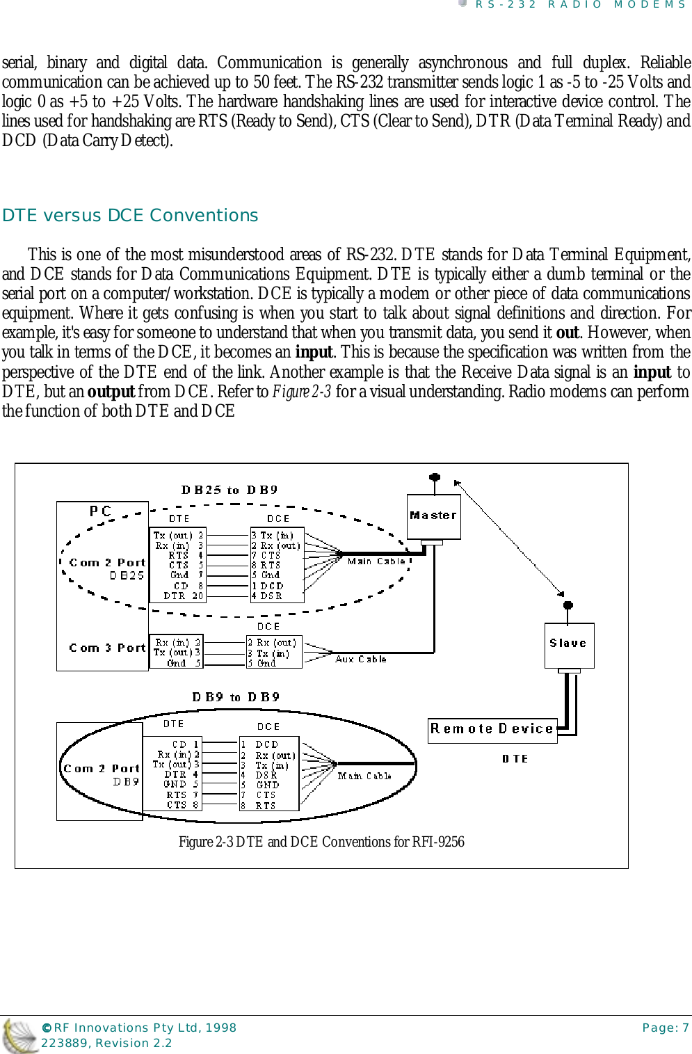
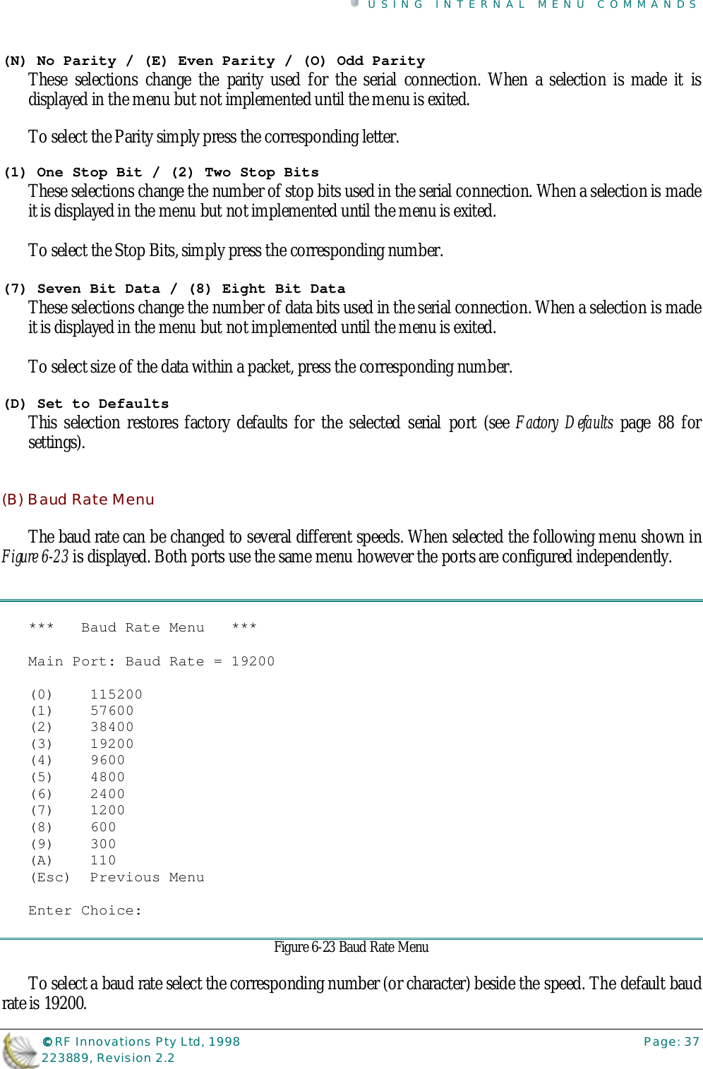
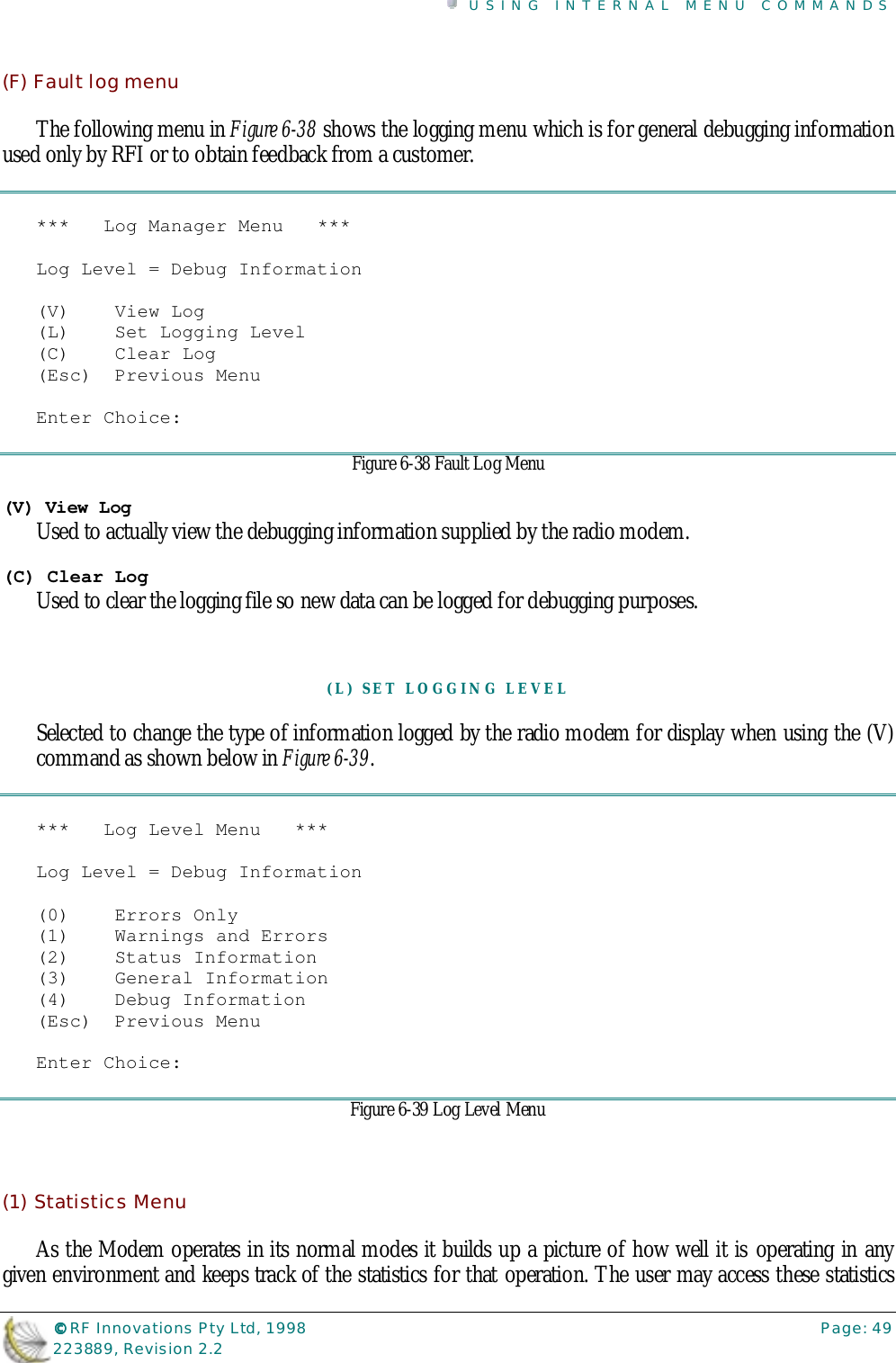
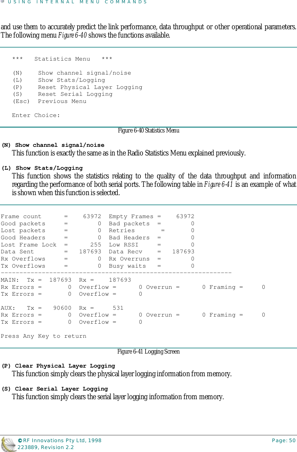
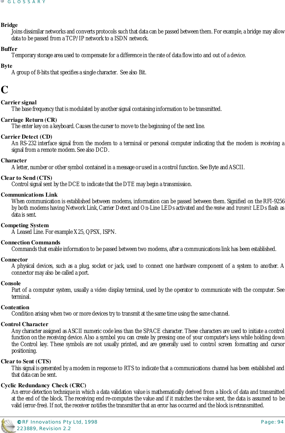
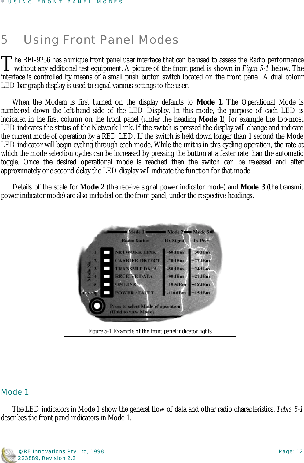
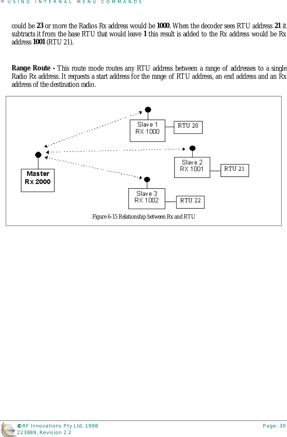
![INSTALLATION©©©© RF Innovations Pty Ltd, 1998 Page: 8223889, Revision 2.23 Installationasic steps can achieve a connection straight away but, if you require a more comprehensive setupthen the information in the main data manual should be read. However, it is recommended thatyou set up a simple connection to gain familiarization with the units and their internal menu system.Setting up for a connectionThe following steps should be followed for setting up communication between a pair of wireless datatransceivers received from the factory with factory default settings:Connect the Main Ports of each radio modem to a serial port of a computer or device, using a suitablecable1.Run a suitable terminal package2 or emulator (on the computer) using the following settings:Communications Settings (RS-232 Com Port)Baud Rate: 19200Data Bits: 8Parity: NoneStop Bits: 1Flow Control: No FlowTerminal SettingsEmulator Mode: None or Standard TTYLocal Echo: offLF to CR on incoming: offLF to CR on outgoing: offFasten the correct type of antennas, as required, to the modems ensuring they are properly seated.Make one of the modems a Master (by default they are Slave) and set its Rx address (modem’snumber) by doing the following:Connect the Local modem’s Auxiliary Port to a COM port of a terminal.Hold Mode Select Button on the front panel of the unit to select Mode 6 – config.This will bring up the Configuration Menu on the terminal.Press ‘R’ to select the “Radio Configuration Menu”.Press ‘M’ to set the unit to a Master.Press ‘L’ to set the Local Rx Address (modem’s number)Press ‘Esc’ (escape) twice.Press ‘Y’ to exit the Menu.At this point a Network Link will be established, and the Slave modem will have the NETWORK LINKand CARRIER DETECT LEDs activated and the POWER LED Flashing. The Master will only have a FlashingPOWER LED. 1 using an RFI pre-made cable [optional] or by a user constructed cable in accordance to the pin configuration in Technical Specifications2 If you don’t have a terminal program that can be set to 19200 baud, you can download our shareware terminal program (RFI’s InTerm) from the RFInnovations Web site (http://www.rfinnovations.com.au/).B](https://usermanual.wiki/STI-Engineering/9256TRX.User-manual/User-Guide-223889-Page-10.png)


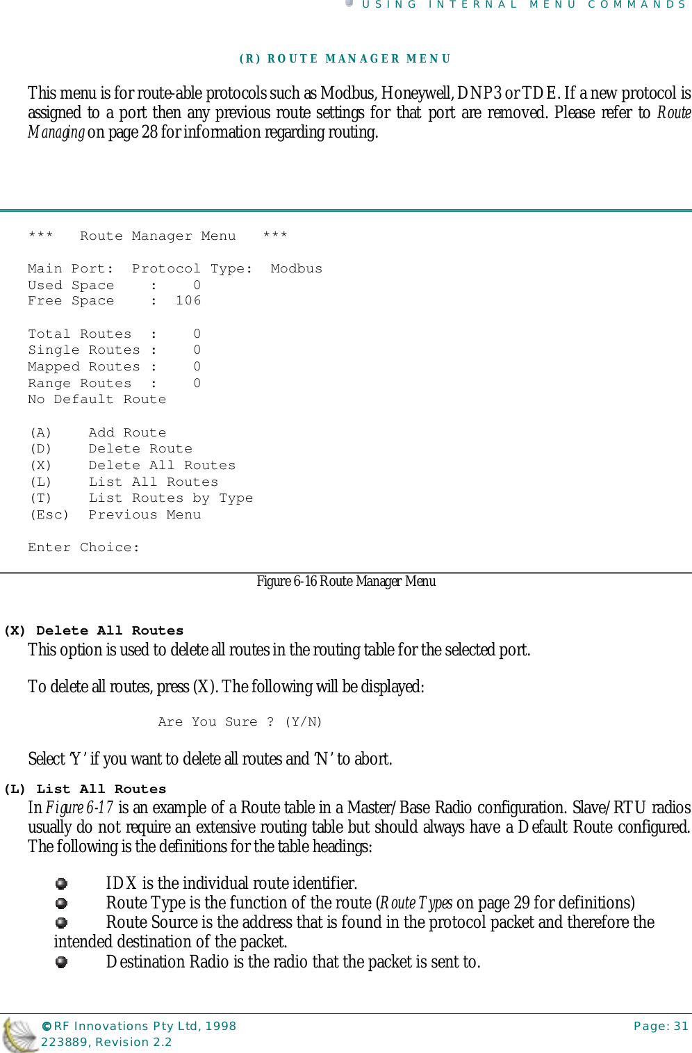
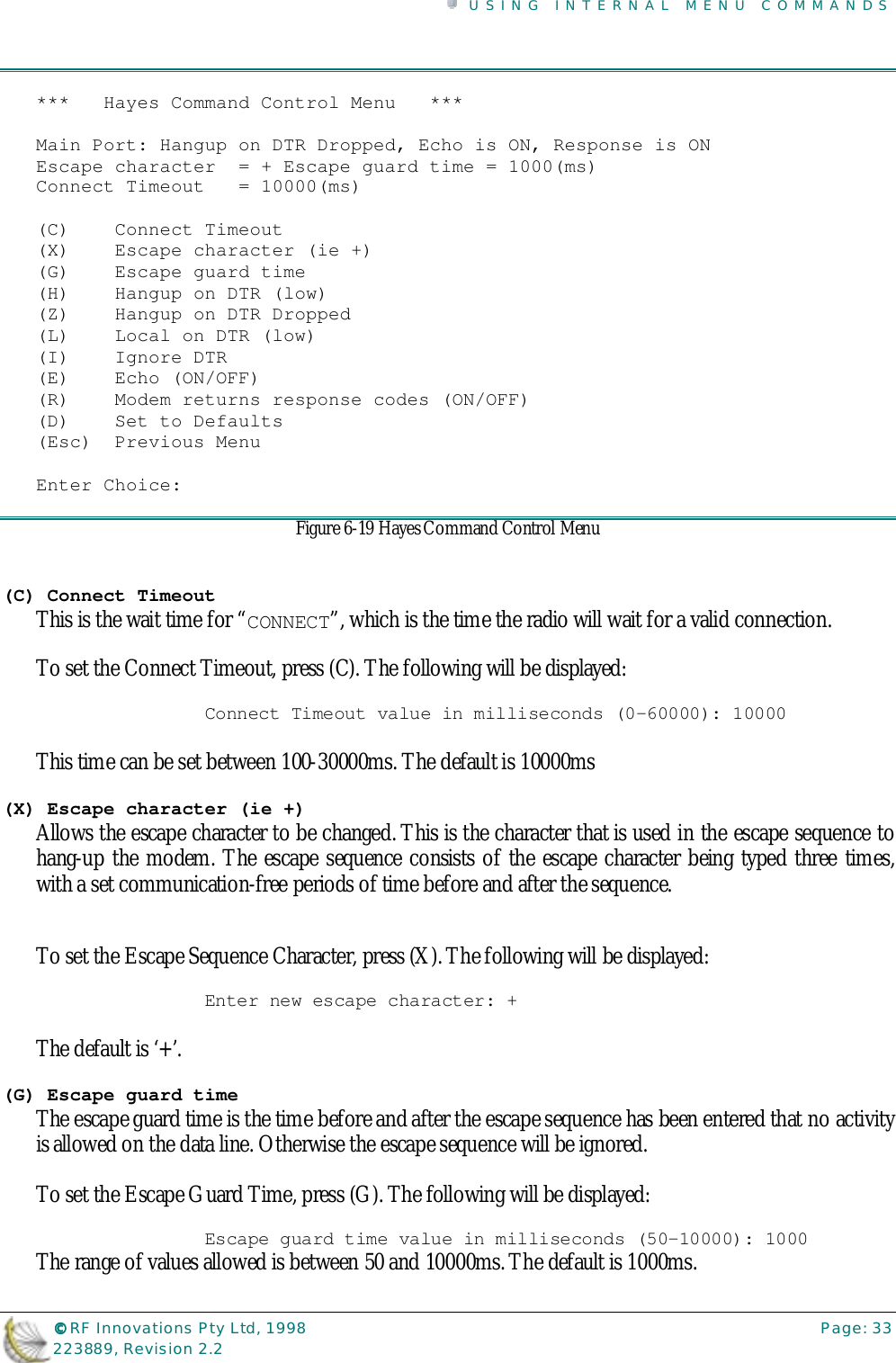
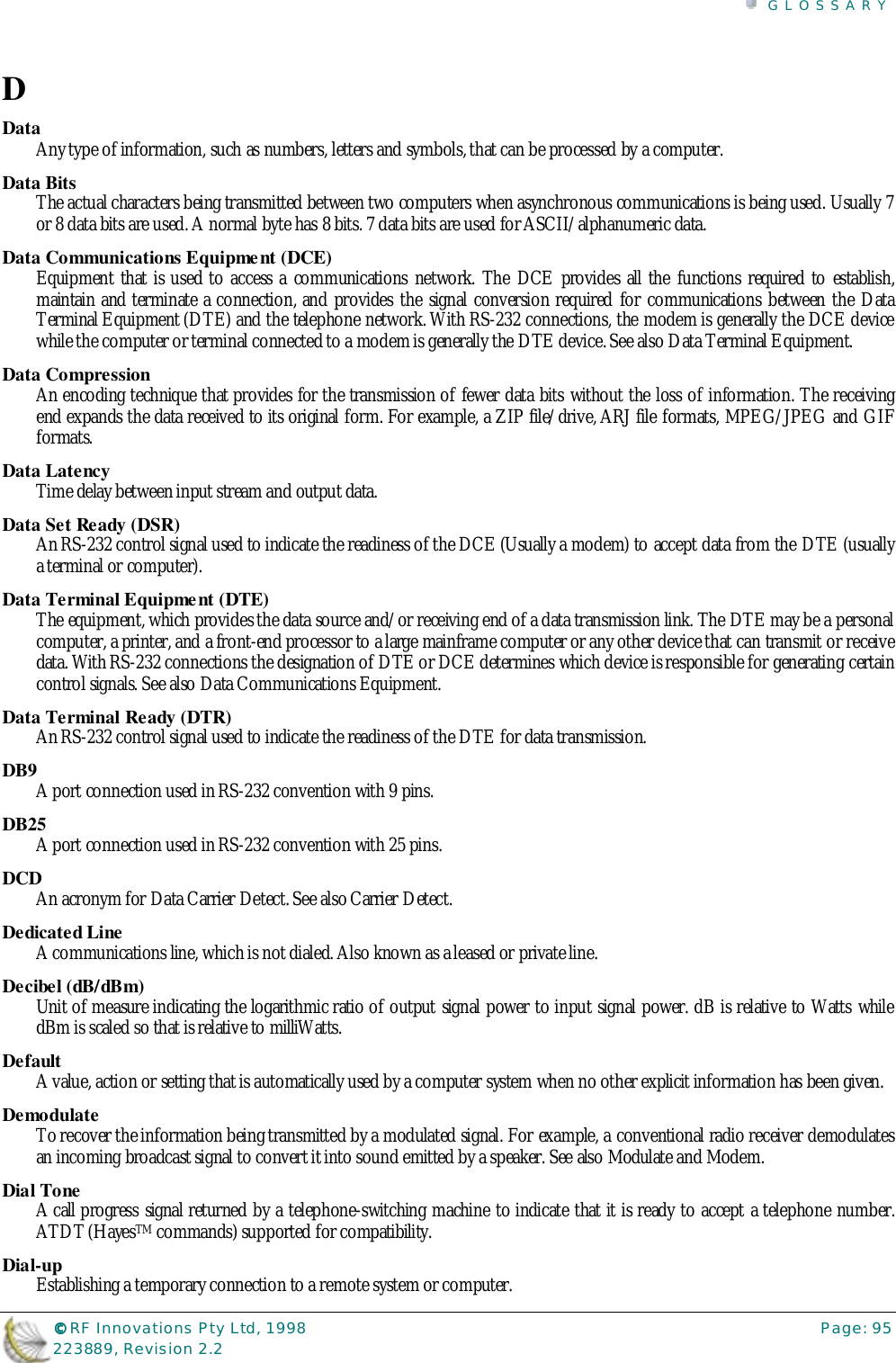
![USING INTERNAL MENU COMMANDS©©©© RF Innovations Pty Ltd, 1998 Page: 32223889, Revision 2.2Idx Route Type Route Source Destination Radio 0 Single Route | Address 10 --> Dest. 9000:00 1 Single Route | Address 12 --> Dest. 9020:00 2 Single Route | Address 16 --> Dest. 9050:00 3 Mapped Route | From [ 20 to 30 ] --> Base 2000:00 4 Mapped Route | From [ 50 to 60 ] --> Base 4200:00 5 Range Route | From [ 80 to 120 ] --> Dest. 6000:00 6 Range Route | From [ 130 to 150 ] --> Dest. 7000:00 7 Default Route | All Other --> Dest. 4000:00Press Any Key to returnFigure 6-17 Route Table Listing(A) Add RouteWhen adding a route, the route type menu (Figure 6-18) is initiated. Please refer to Route Types on page29 for a definition on the routes available.*** Route Type Menu ***(D) Default Route(S) Single Route(M) Mapped Route(R) Range Route(Esc) Previous MenuEnter Choice:Figure 6-18 Route Selection Menu(D) Delete a RouteWhen this option is selected the route type menu (Figure 6-18) is brought up to select the type of routeto be deleted. Once a route type is selected all the routes of that type is listed and the IDX (routeidentification number) is used to select the desired route to delete.(L) List Route by TypeWhen this option is selected a route type menu (Figure 6-18) is brought up to select the type of route tobe listed. Once a route type is selected all the routes of that type is listed.(M) HAYES COMMAND CONTROL MENUThe Hayes Command Control Menu allows the user to change Hayes compatible responses andresponse codes. For example, it is here in this menu the user can toggle the echo on/off and set theescape sequence character, etc.](https://usermanual.wiki/STI-Engineering/9256TRX.User-manual/User-Guide-223889-Page-34.png)