STI Engineering RFI148 VHF PAGING TRANSMITTER User Manual RFI 148 250W VHF Paging Transmitter
STI Engineering Pty Ltd VHF PAGING TRANSMITTER RFI 148 250W VHF Paging Transmitter
UserManual.wiki
>
STI Engineering
>
RFI148 User Manual
User Manual
Navigation menu
Upload a User Manual
Namespaces
Wiki Guide
HTML
PDF
Info
Views
User Manual
Discussion / Help
Navigation

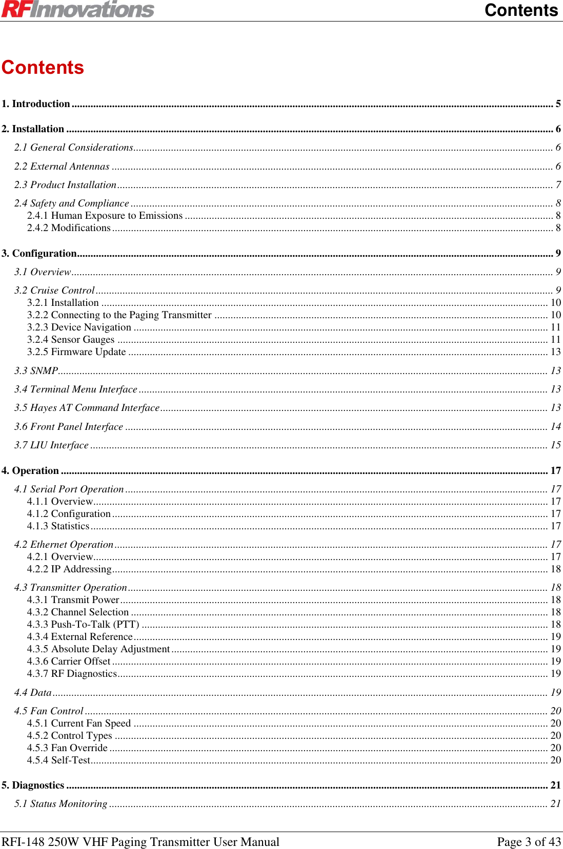


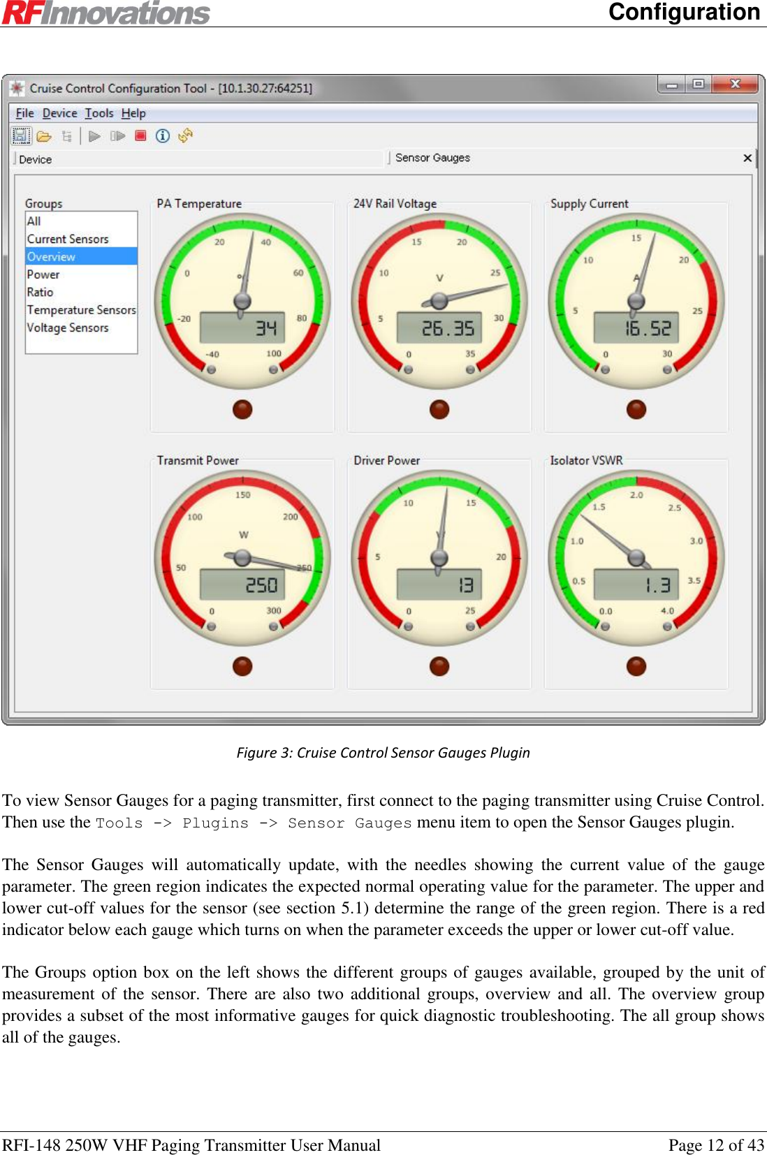
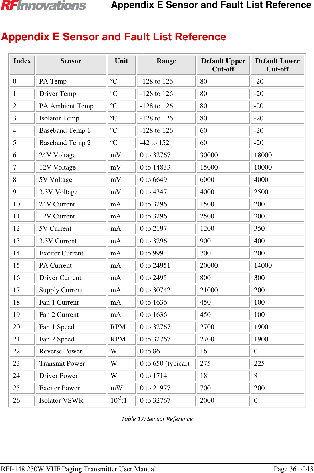
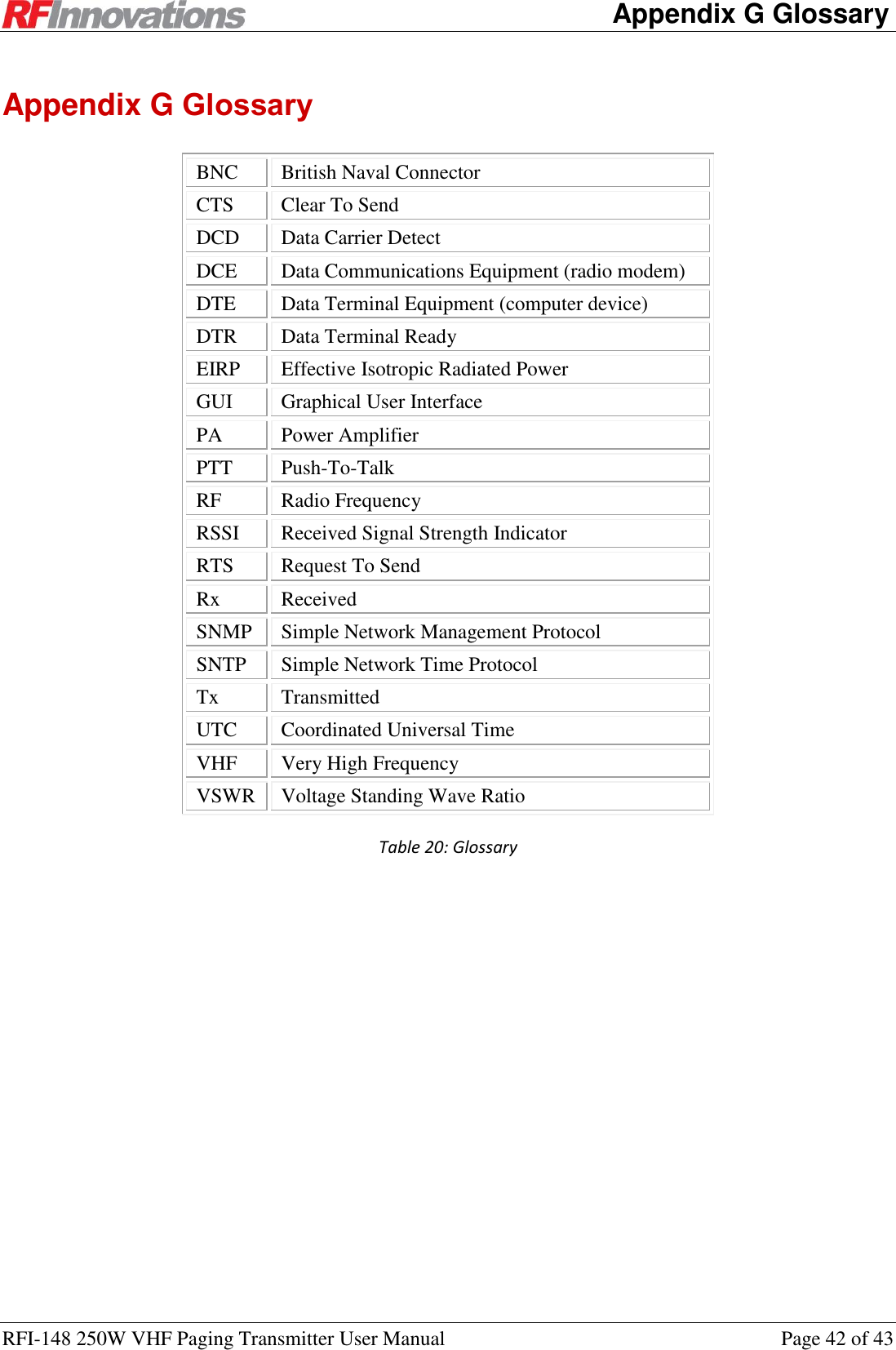
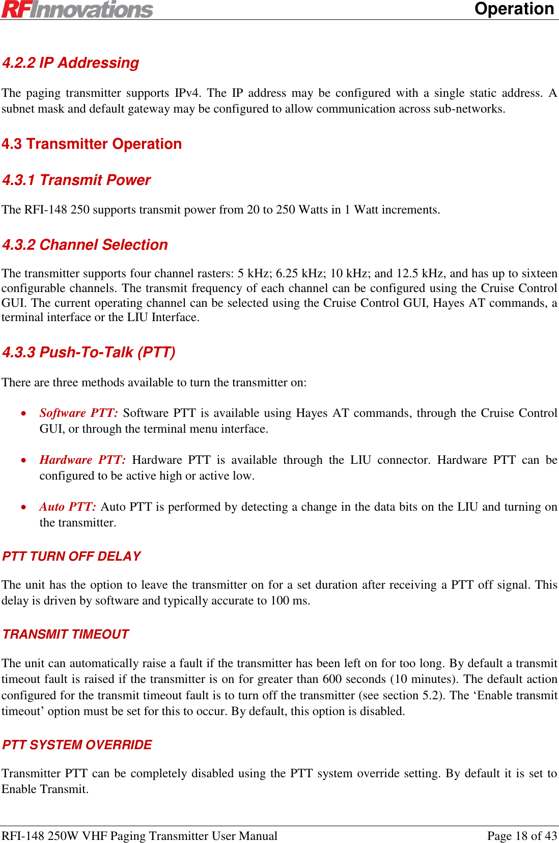
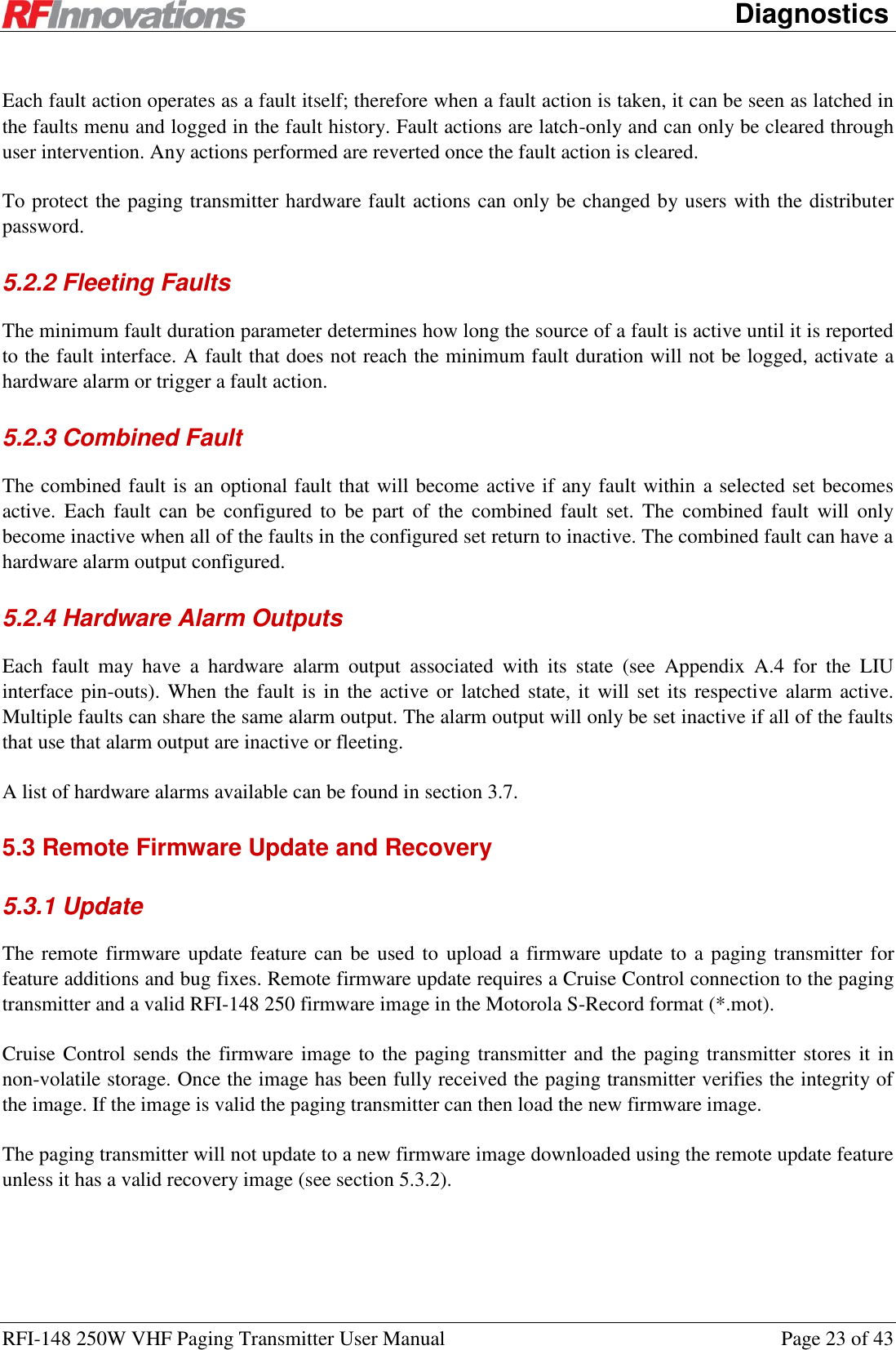
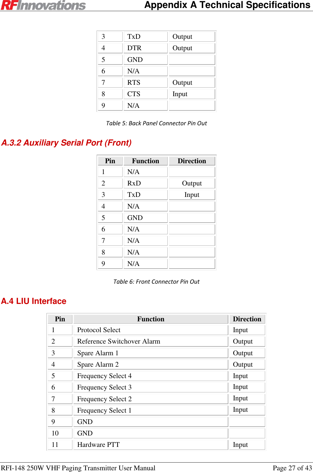
![Configuration RFI-148 250W VHF Paging Transmitter User Manual Page 13 of 43 3.2.5 Firmware Update Cruise Control supports the updating of device firmware from Motorola S-Record image files (*.mot). Cruise Control will only allow firmware images that are compatible with the paging transmitter to be uploaded. To upload a firmware image use the Device -> Load Firmware menu item. A windows explorer dialog will open, navigate to where the firmware image is on the computer, select the image and click upload. The progress bar at the bottom right will show the progress of the firmware update. Once the upload has finished the paging transmitter will reset to apply the update. While updating the paging transmitter cannot key up or respond to queries. Cruise Control will automatically reconnect once the update is complete. For information on this feature as related to the paging transmitter firmware, which includes the firmware recovery mechanism, see section 5.3. 3.3 SNMP The paging transmitter includes a built-in SNMP agent. Not all configuration and diagnostic parameters may be queried via SNMP. See Appendix C.2 for a list of values which may be queried via SNMP. SNMP versions 1 and 2c are supported. The community string ‘public’ should be used when issuing SNMP requests. The agent responds on UDP port 161 is compatible with standard SNMP managers and other SNMP client applications. An SMI MIB file defining OIDs for this product is available. 3.4 Terminal Menu Interface The terminal menu provides access to all configuration parameters in the radio. To access the terminal menu execute the AT? command at the Hayes AT command interface. See section 3.5 on page 13 for information on executing AT commands. The terminal menu will not be started if it is open on another port, instead the BUSY response is returned. The terminal menu is available over serial, UDP (ports 64250, 64251 and 64252) and TCP (port 23). 3.5 Hayes AT Command Interface The paging transmitter supports Hayes ATtention commands. These are used to query and change device configuration and probe performance parameters. AT commands are available via serial port, and via TCP port 23 on the Ethernet interface. The format for the query and configuration AT command is: ATxxx<[I1, I2, … In]><=value><TERM>](https://usermanual.wiki/STI-Engineering/RFI148/User-Guide-1891476-Page-13.png)
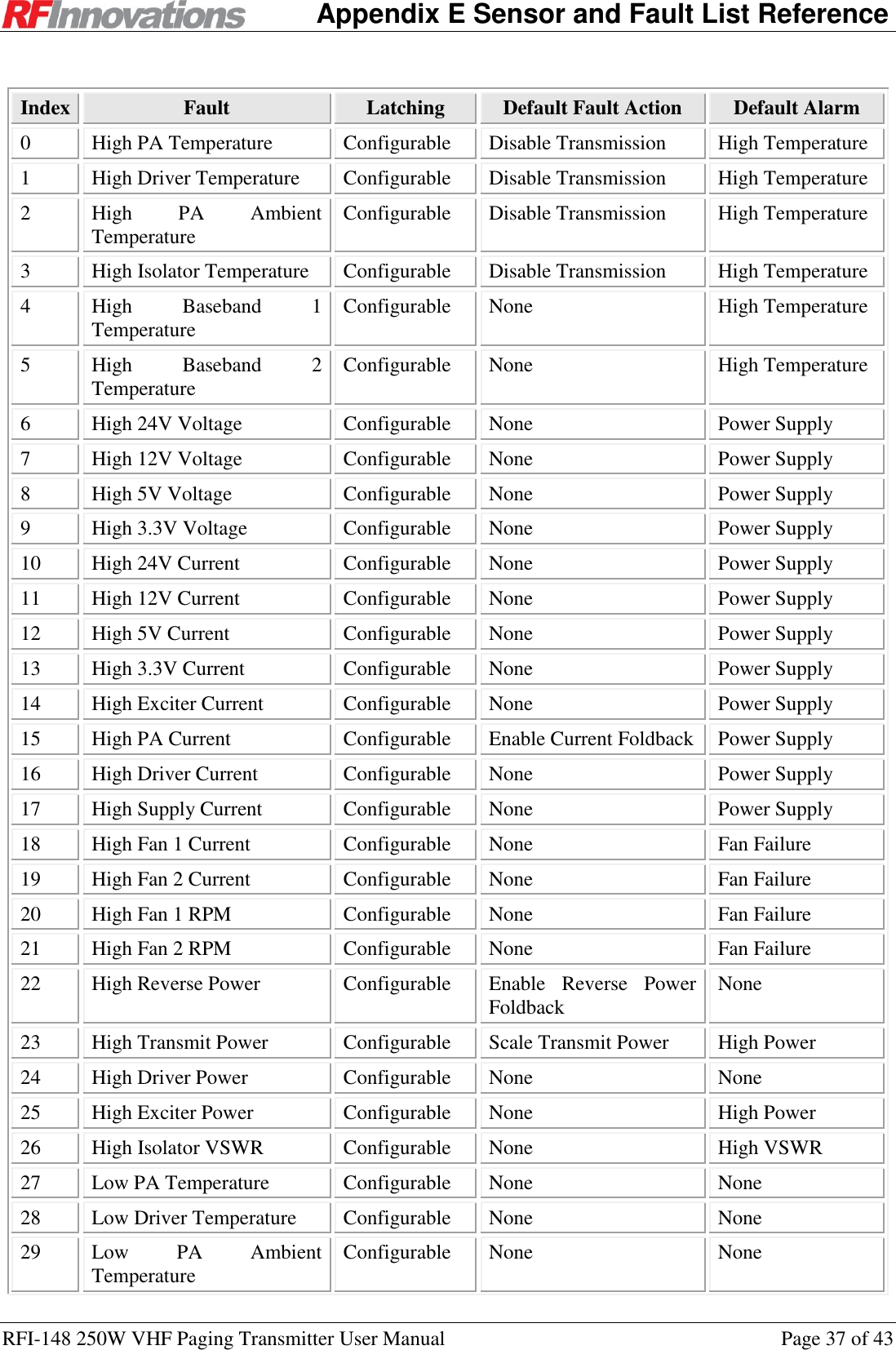
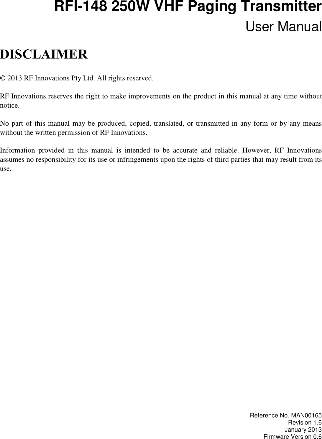
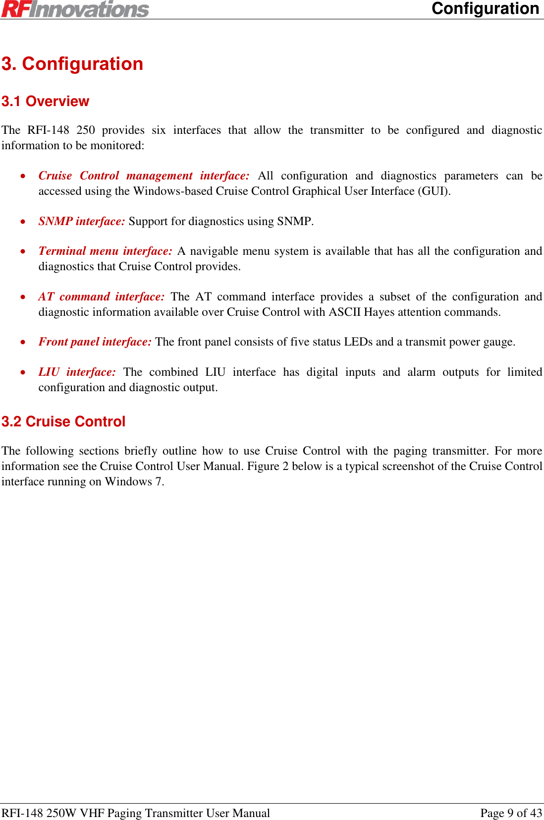
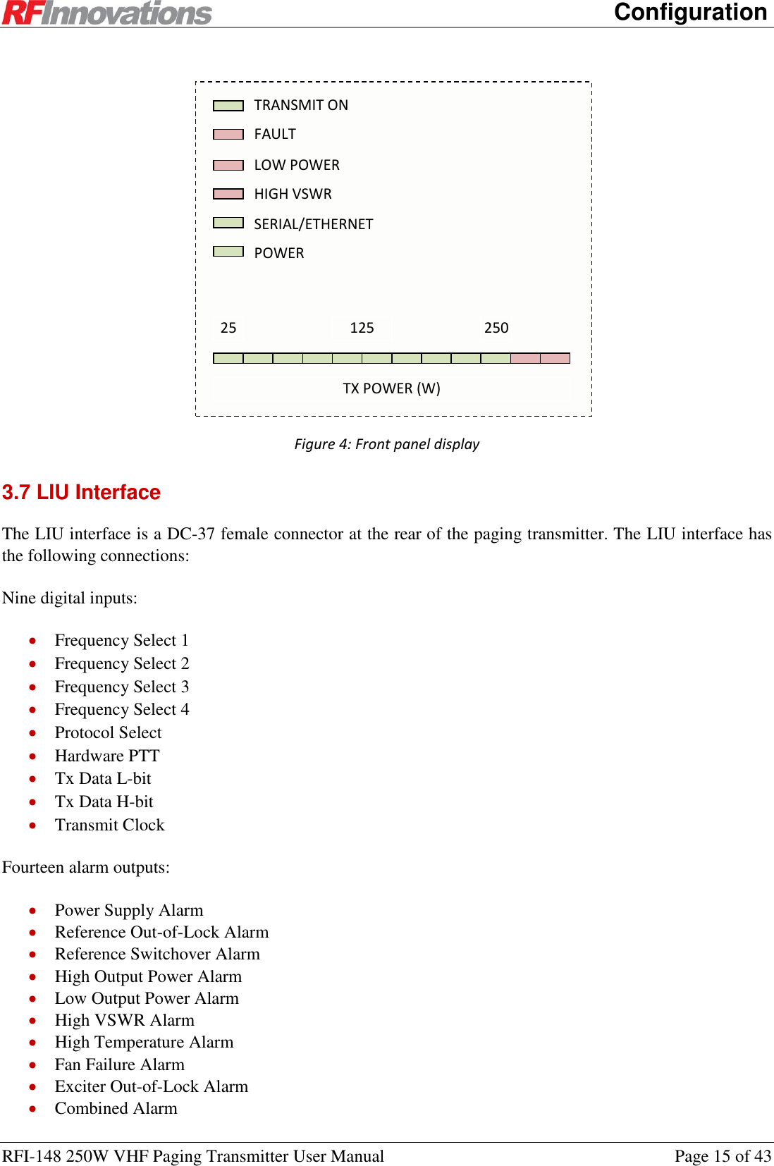
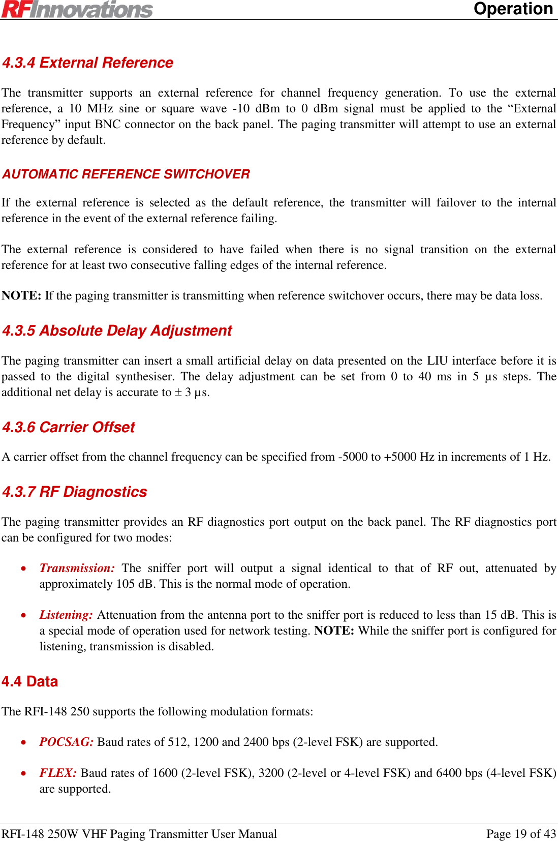
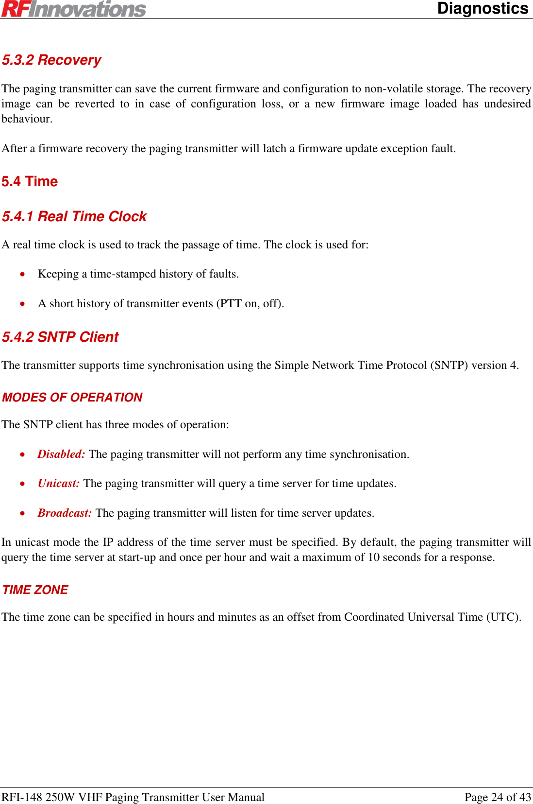
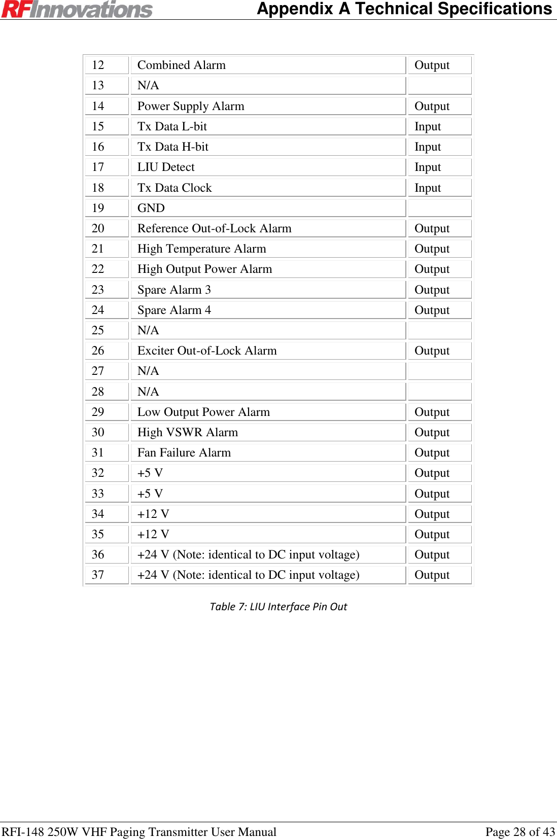
![Configuration RFI-148 250W VHF Paging Transmitter User Manual Page 14 of 43 Where: AT is the attention code. All AT commands must be prefixed with AT. This is case insensitive, so At, aT, or at can also be used. xxx is the actual command. The list of valid AT commands is given in Appendix D on page 33. <[I1, I2, … In]> is an optional section that allows the specification of an index. Indexes are used to access one of an array of similar items. For example, the Crescendo radio has two serial ports which can both have different configurations. The command ATS52[0]=1004 set the point-to-point destination on the main port, while the command ATS52[1]=1004 will set the point-to-point destination on the auxiliary port. <=value> is an optional section that is used to set the value of a configuration parameter. If this section is omitted, then the value of the configuration parameter will be displayed. <TERM> is the terminator for the AT command. A terminator can consist of a carriage return (ASCII value 13Decimal) or a carriage return followed by a line feed (ASCII value 10Decimal). For each AT command that is issued a response is generated. The list of responses to AT commands is shown in Table 1. Response Code Response Number Description OK 0 Returned whenever a command is entered that is executed correctly. ERROR 4 Returned whenever a command is invalid or could not be executed. BUSY 7 Returned when an attempt is made to enable the menu via AT? but the menu system is already enabled on the other serial port. Table 1: AT command response codes 3.6 Front Panel Interface The front panel interface consists of 6 status LEDs and a transmit power gauge. The panel is illustrated in Figure 4 and the function of each LED is described in Table 2. LED Colour Description Transmit On Green Turns on when the transmitter is on. Fault Red Turns on when any fault is active. Low Power Red Turns on when the sensed transmit power is lower than the lower cut-off value as specified in the sensor parameters. High VSWR Red Turns on when the isolator VSWR is higher than the higher cut-off value as specified in the sensor parameters. Serial/Ethernet Green Flashes when serial or Ethernet data is transmitted or received. Power Green Turns on/off at 1 Hz while power is supplied. Power Gauge Green/Red A bar graph displaying current transmit power. Table 2: Front panel LED descriptions](https://usermanual.wiki/STI-Engineering/RFI148/User-Guide-1891476-Page-14.png)
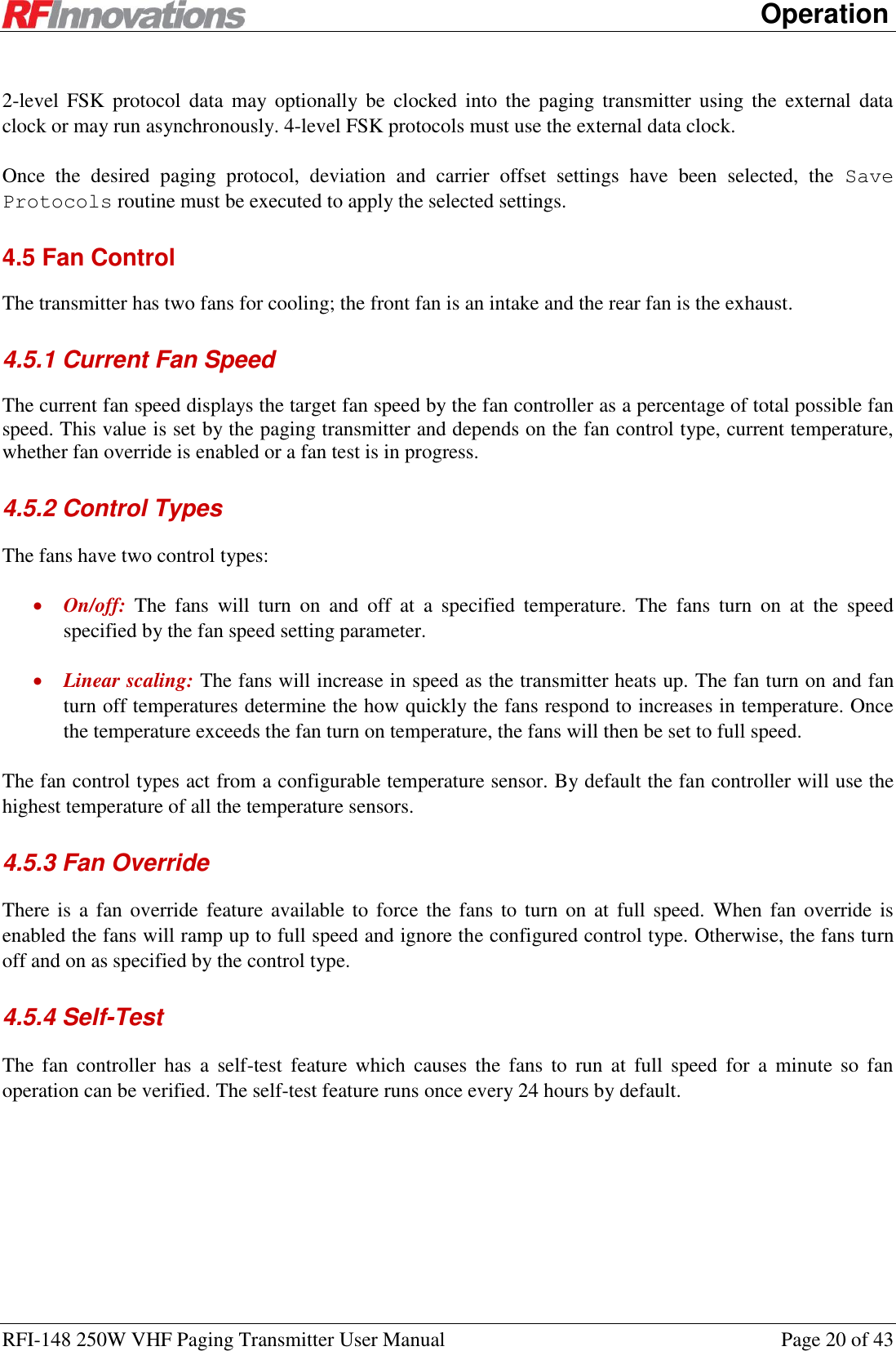

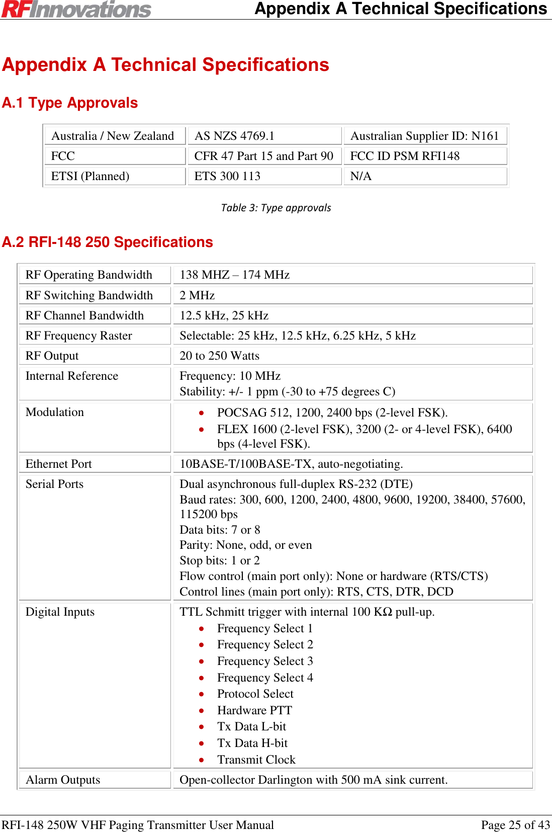
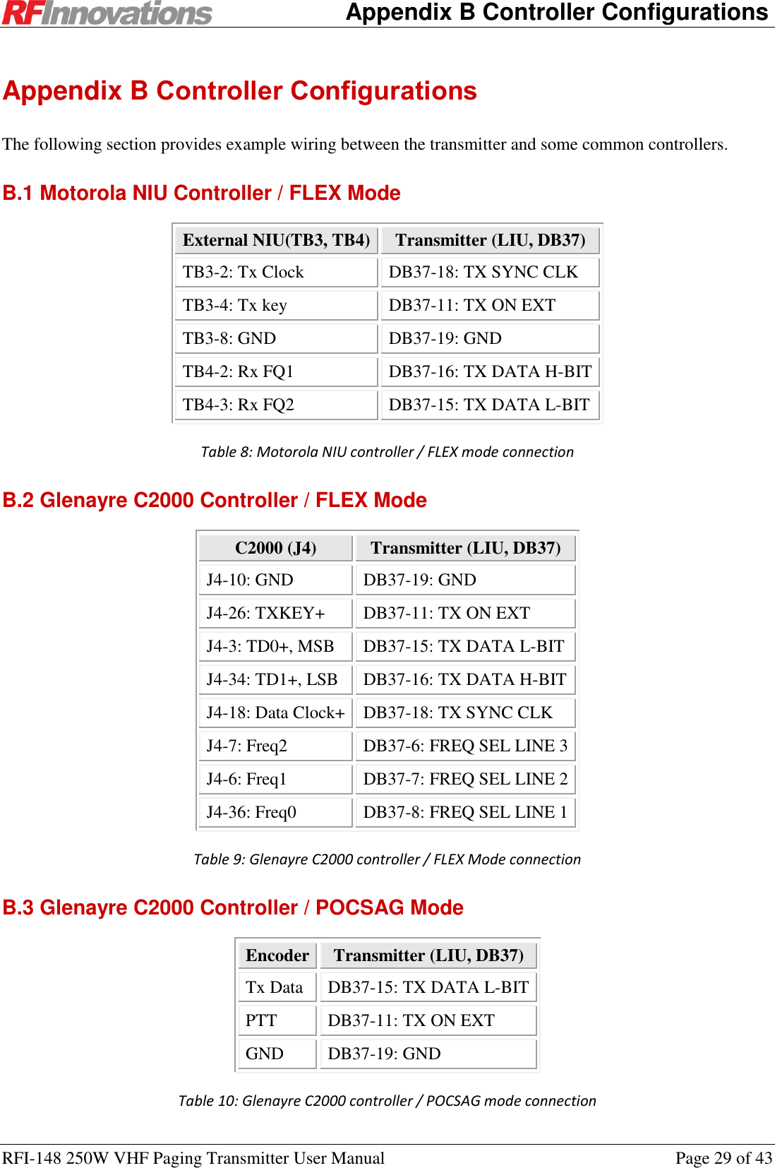
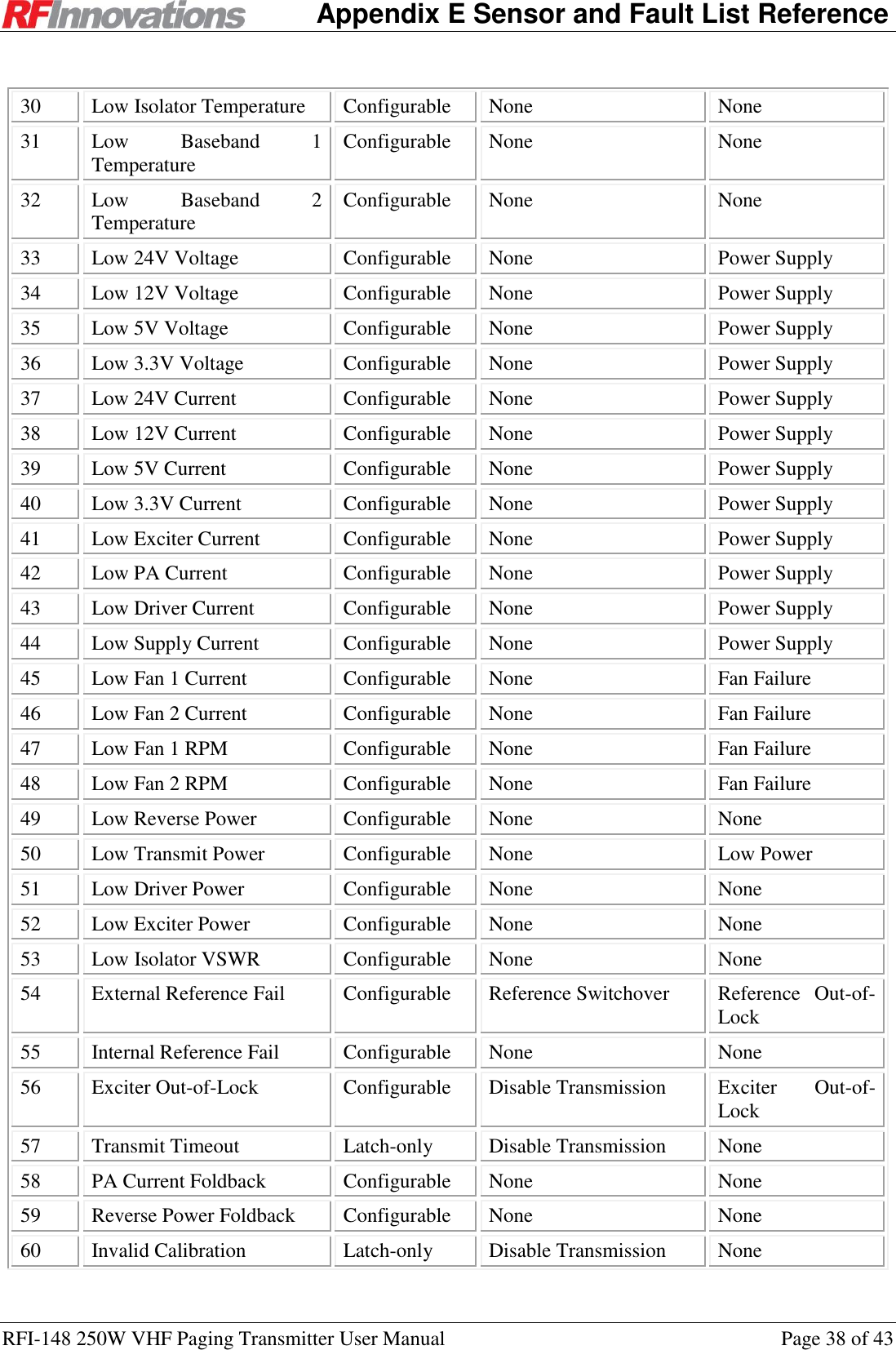
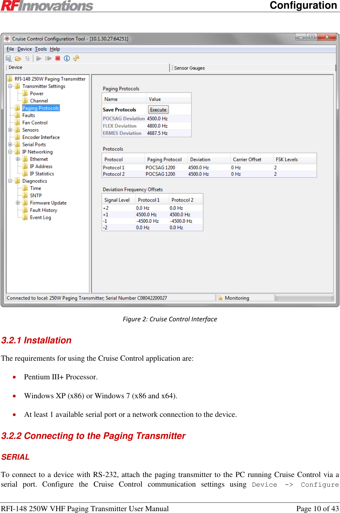
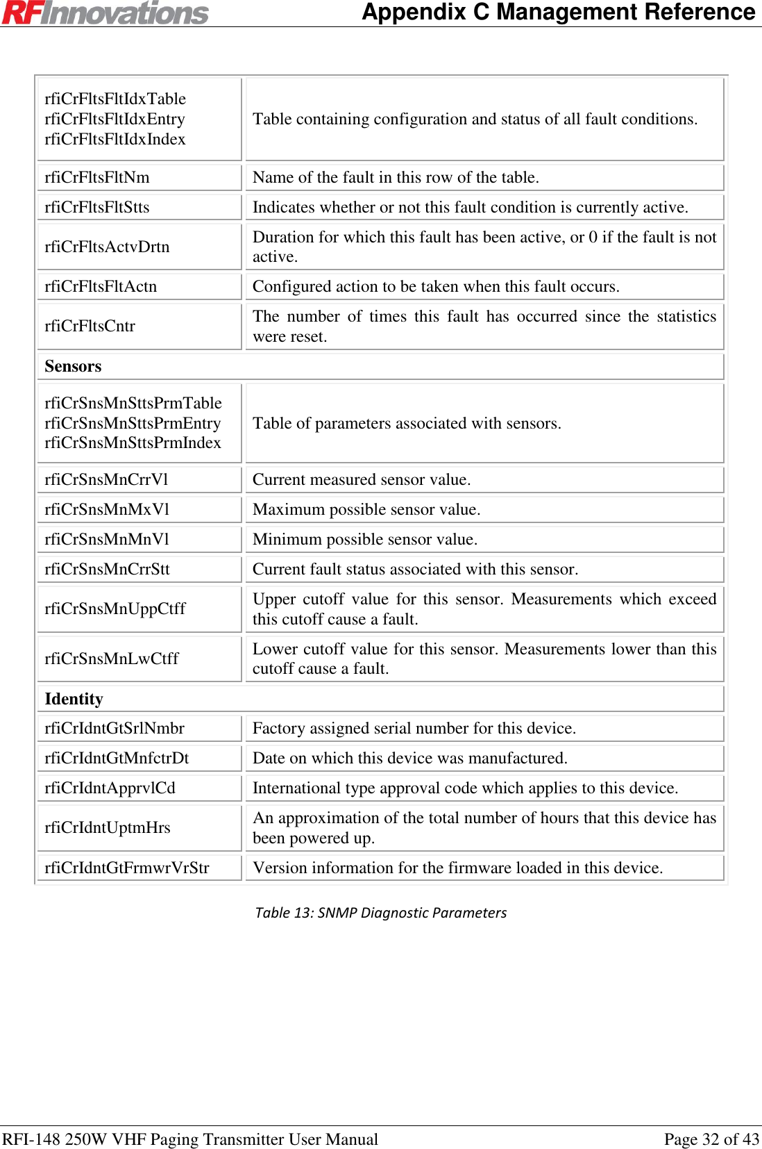
![Appendix C Management Reference RFI-148 250W VHF Paging Transmitter User Manual Page 31 of 43 Appendix C Management Reference C.1 Serial Port Diagnostics Name Description AT Rx Total The size of the input buffer. I20[p,0] Rx Used The number of bytes currently stored in the input buffer. I20[p,1] Rx Bytes The total number of bytes received. I20[p,2] Rx Errors The total number of receive errors that have occurred. Sum of Rx Overflows, Rx Overruns, Rx Framing, and Rx Parity errors. I20[p,3] Rx Overflows The number of receive overflow errors that have occurred. An overflow occurs when data is received, but the buffer is full. I20[p,4] Rx Overruns The number of overrun errors that have occurred. An overrun occurs when the device is overloaded and cannot handle the incoming data. I20[p,5] Rx Framing The number of framing errors that have occurred. Framing errors usually occur due to mismatched serial port baud rates. I20[p,6] Rx Parity The number of serial parity errors that have been detected. I20[p,7] Tx Total The size of the output buffer. I20[p,8] Tx Used The number of bytes currently stored in the output buffer. I20[p,9] Tx Bytes The total number of bytes that have been transmitted. I20[p,10] Tx Errors The total number of errors that have occurred while transmitting. This is equal to the Tx Overflows count. I20[p,11] Tx Overflows The number of transmit overflow errors that have occurred. This occurs when there is data to transmit, but the buffer is full. I20[p,12] Table 12: Serial Port Statistics C.2 SNMP Diagnostic Parameters SNMP Textual Name Description Radio parameters rfiChnChnCtrlChnnlsTable rfiChnChnCtrlChnnlsEntry rfiChnChnCtrlChnnlsIndex Table of frequencies for all radio channels. rfiChnChnCtrlChnnlNmbr Radio channel number. rfiChnChnCtrlTxFrq Radio channel transmit frequency. Faults](https://usermanual.wiki/STI-Engineering/RFI148/User-Guide-1891476-Page-31.png)
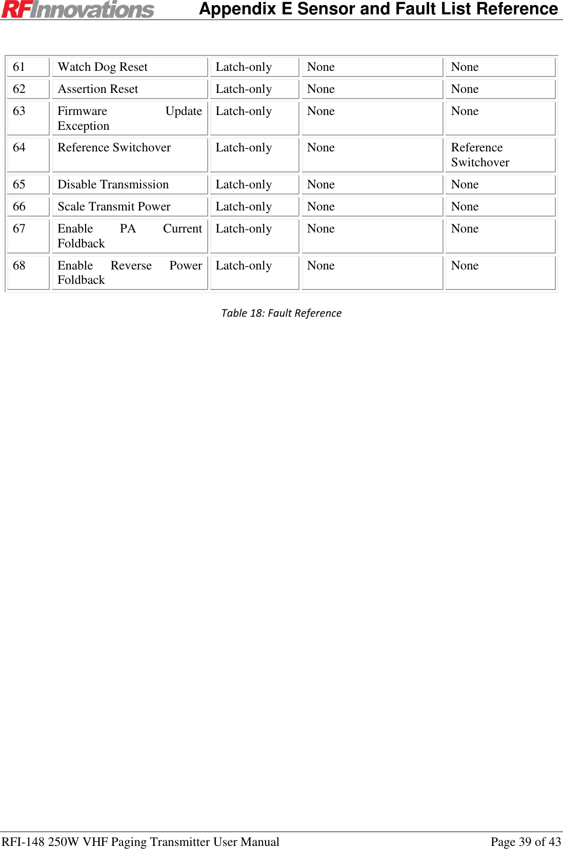
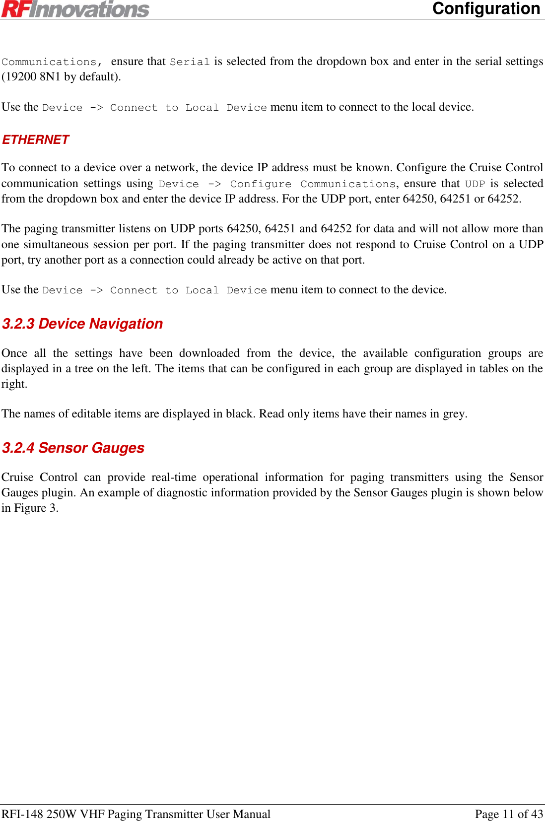
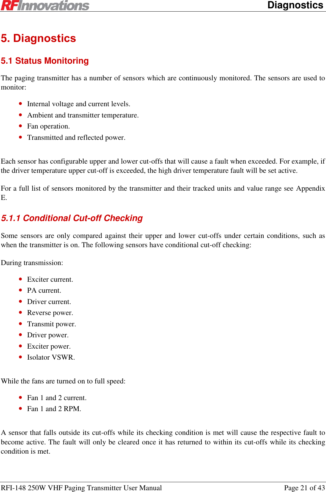
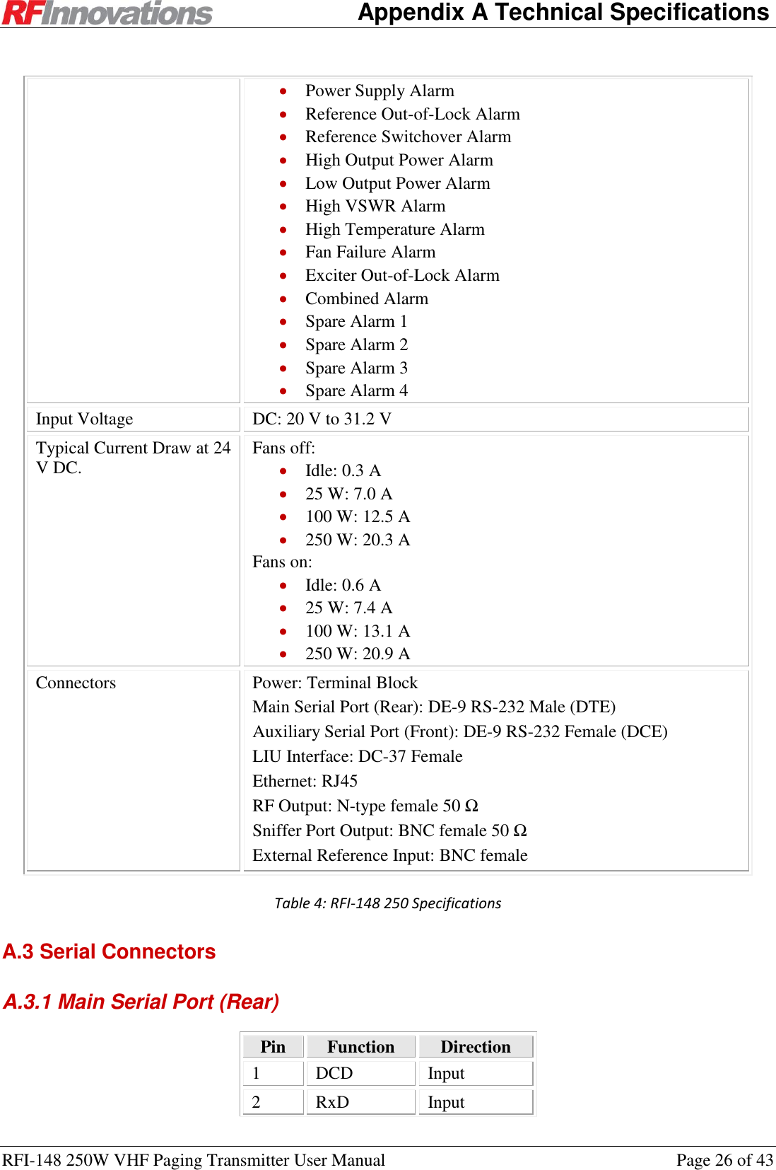
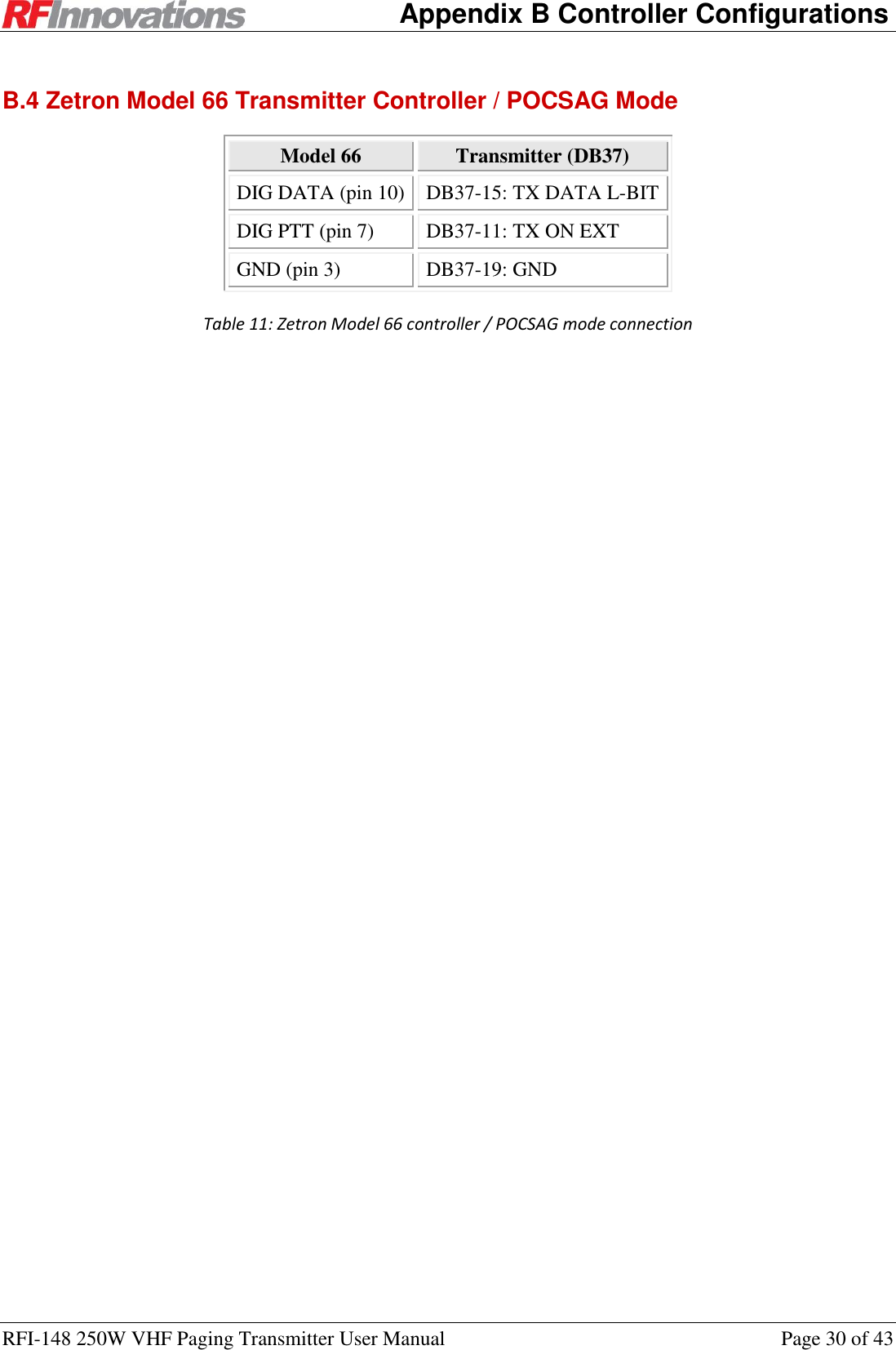
![Appendix D Hayes References RFI-148 250W VHF Paging Transmitter User Manual Page 33 of 43 Appendix D Hayes References D.1 General Commands Command Name Notes ATI100 Read All Sensors Returns a list of the current value of all sensors, separated by commas and ended by a period, carriage return and line feed. See Appendix E for the sensor reference. ATI101 Read Active Faults Returns either: a variable list of active fault indexes separated by commas; or “None”, followed by a period, line feed and carriage return. See Appendix E for the fault reference. ATI102 Read Upper Sensor Limits Returns a list of the current upper sensor cut-offs for all sensors, separated by commas and ended by a period, carriage return and line feed. See Appendix E for the sensor reference. ATI103 Read Lower Sensor Limits Returns a list of the current lower sensor cut-offs for all sensors, separated by commas and ended by a period, carriage return and line feed. See Appendix E for the sensor reference. AT&F1 Factory Reset Resets all settings to factory defaults. AT&T9 Reset Causes the device to reboot. AT? Enable Menu Starts the terminal menu this port. AT%30 Enable Cruise Control Enables Cruise Control on this port. Waits for 10 seconds after executing with no further data input to return to normal Hayes mode. Table 14: Hayes General Commands D.2 I-Registers Command Name Notes ATI0 Product String Returns the product string. ATI4 Version String Returns the version string. ATI5 Manufacture Date Returns the manufacture date. ATI6 Serial Number Returns the device serial number. ATI20[p, s] Serial Port Statistics Returns a serial port statistic where p selects port (0: main, 1: auxiliary) and s selects statistic (0 to 12, in the order listed in Table 12).](https://usermanual.wiki/STI-Engineering/RFI148/User-Guide-1891476-Page-33.png)
![Appendix D Hayes References RFI-148 250W VHF Paging Transmitter User Manual Page 34 of 43 ATI90[p] Current status parameter Returns the current value of a status parameter where p selects a parameter. See Appendix E for the sensor reference.* ATI91[p] Maximum status parameter Returns the maximum recorded value of a status parameter. See Appendix E for the sensor reference.* ATI92[p] Minimum status parameter Returns the minimum recorded value of a status parameter. See Appendix E for the sensor reference.* ATI93[p] Status parameter upper cut-off Returns the upper cut-off value of a status parameter where p selects a parameter. See Appendix E for the sensor reference.* ATI96[p] Status parameter lower cut-off Returns the lower cut-off value of a status parameter where p selects a parameter. See Appendix E for the sensor reference.* ATI151 Clear All Latched Faults Clears all faults in the latched state. Table 15: Hayes I-Register Commands * The parameter p is an integer index, as shown in the Index column of Table 17 Command Name Notes ATS45 Transmit Power Get or set transmit power in Watts. ATS54 Current Channel Get or set the current channel. ATS100[p] Baud Get or set the baud rate for serial port p. 1: 300 2: 600 3: 1200 4: 2400 5: 4800 6: 9600 8: 19200 9: 38400 10: 57600 11: 115200 ATS101[p] Parity Get or set the parity for serial port p. 0: None 1: Even 2: Odd ATS102[p] Data Bits Get or set the data bits for serial port p. 0: 7 1: 8 ATS103[p] Stop Bits Get or set the stop bits for serial port p.](https://usermanual.wiki/STI-Engineering/RFI148/User-Guide-1891476-Page-34.png)
![Appendix D Hayes References RFI-148 250W VHF Paging Transmitter User Manual Page 35 of 43 Command Name Notes 0: 1 1: 2 ATS104 Main Port Flow Control Note that this command cannot have a [p] port specifier. 0: None 2: Hardware (RTS / CTS) ATS180 Enable Hardware Frequency Select 0: Disabled 1: Enabled Table 16: Hayes S-Register Commands](https://usermanual.wiki/STI-Engineering/RFI148/User-Guide-1891476-Page-35.png)