STI Engineering RFI150H VHF Digital Mobile Radio User Manual Crescendo VHF Half Duplex
STI Engineering Pty Ltd VHF Digital Mobile Radio Crescendo VHF Half Duplex
UserManual.wiki
>
STI Engineering
>
RFI150H User Manual
>
users manual
Contents
1.
users manual
2.
revised user manual
users manual
Navigation menu
Upload a User Manual
Namespaces
Wiki Guide
HTML
PDF
Info
Views
User Manual
Discussion / Help
Navigation

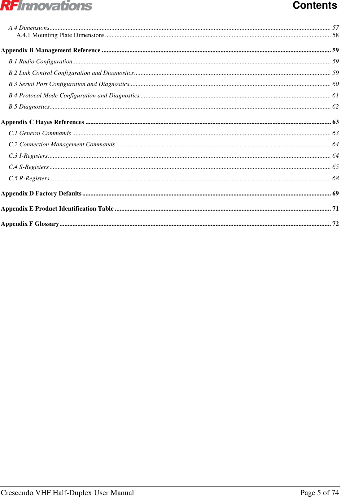

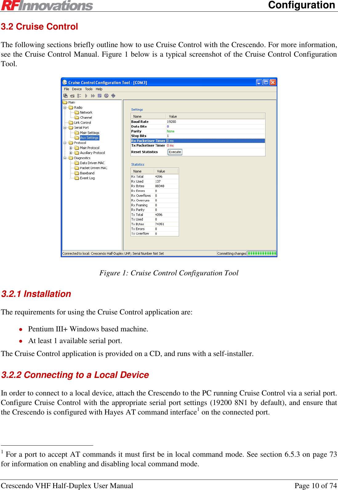
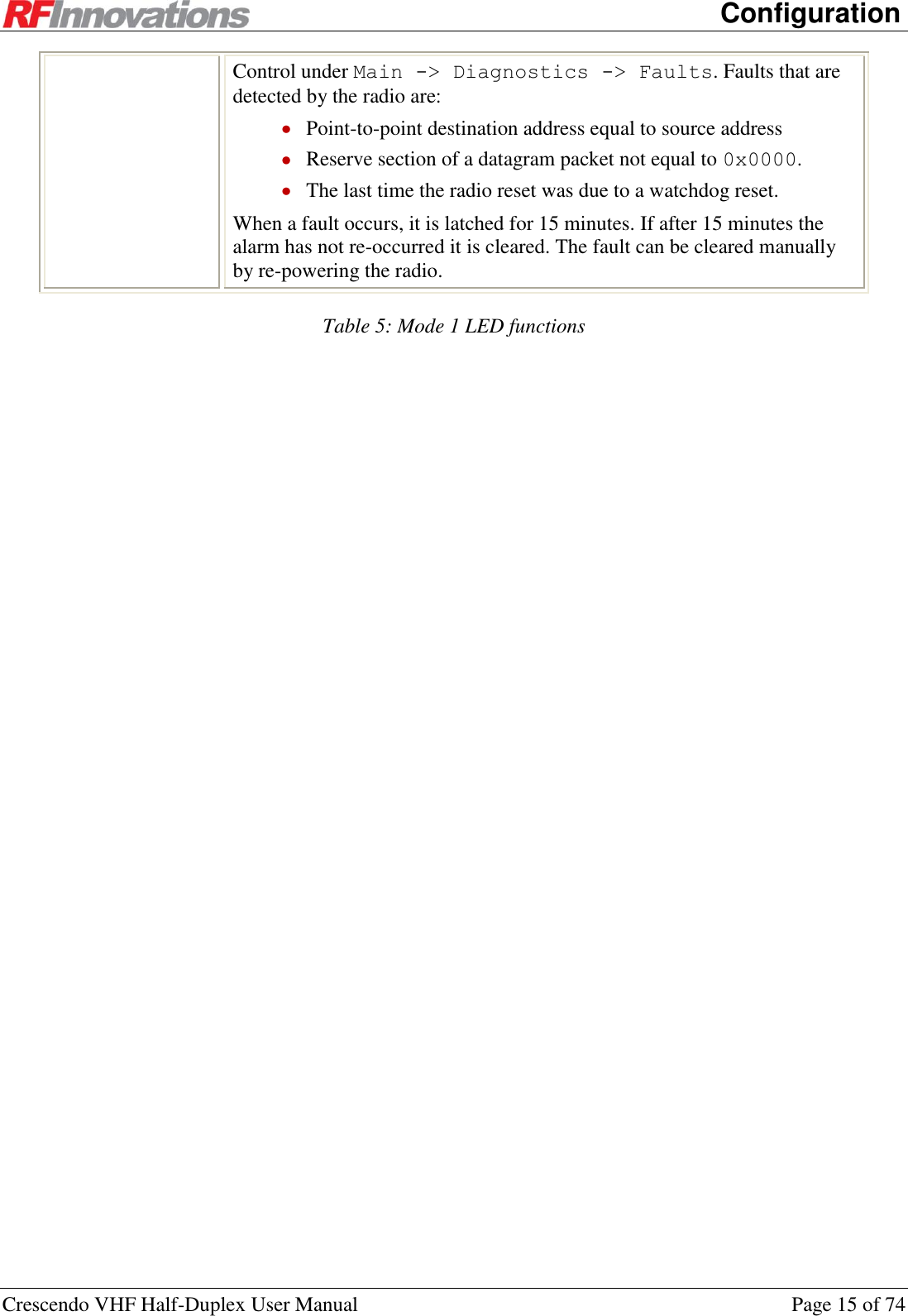
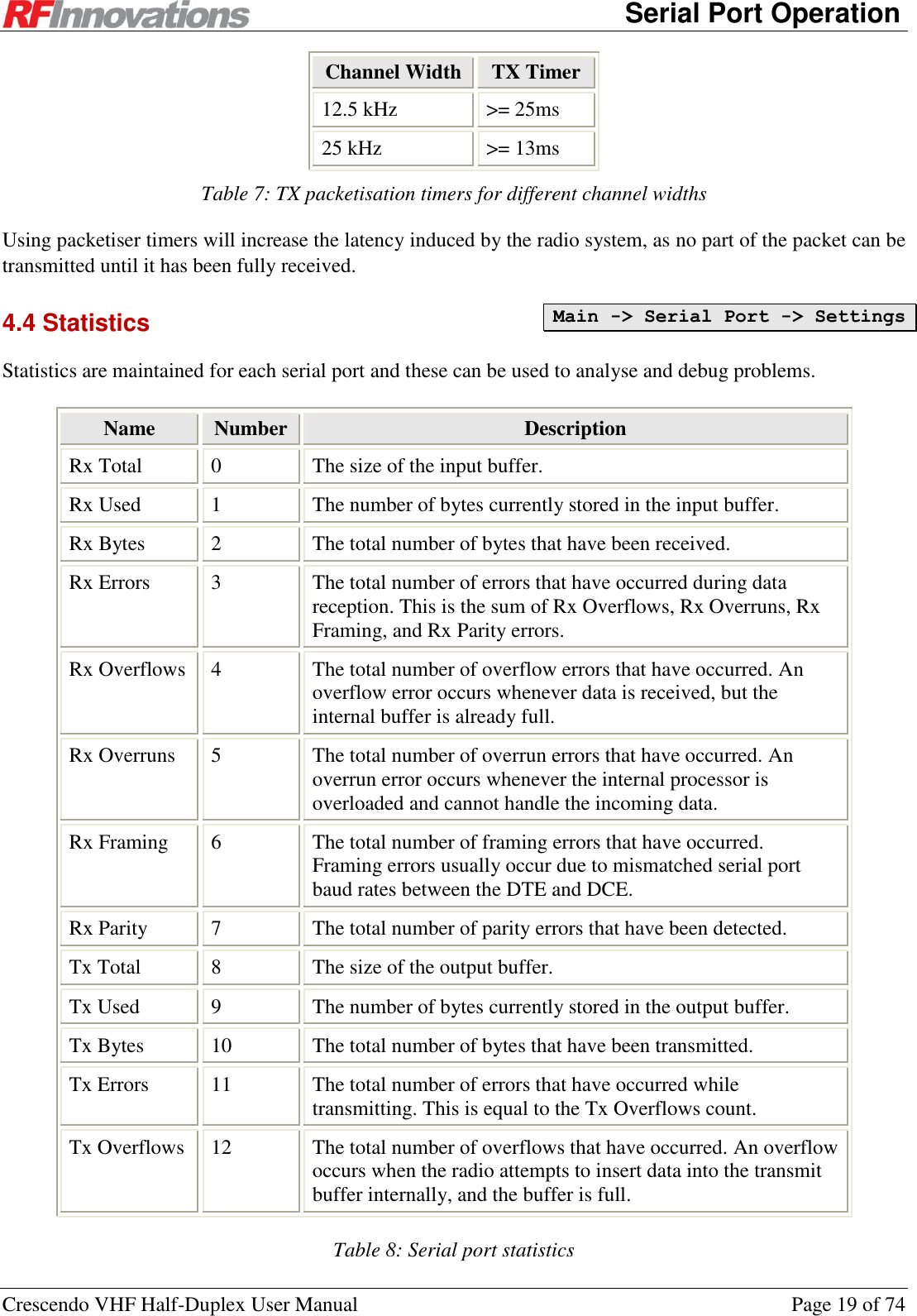
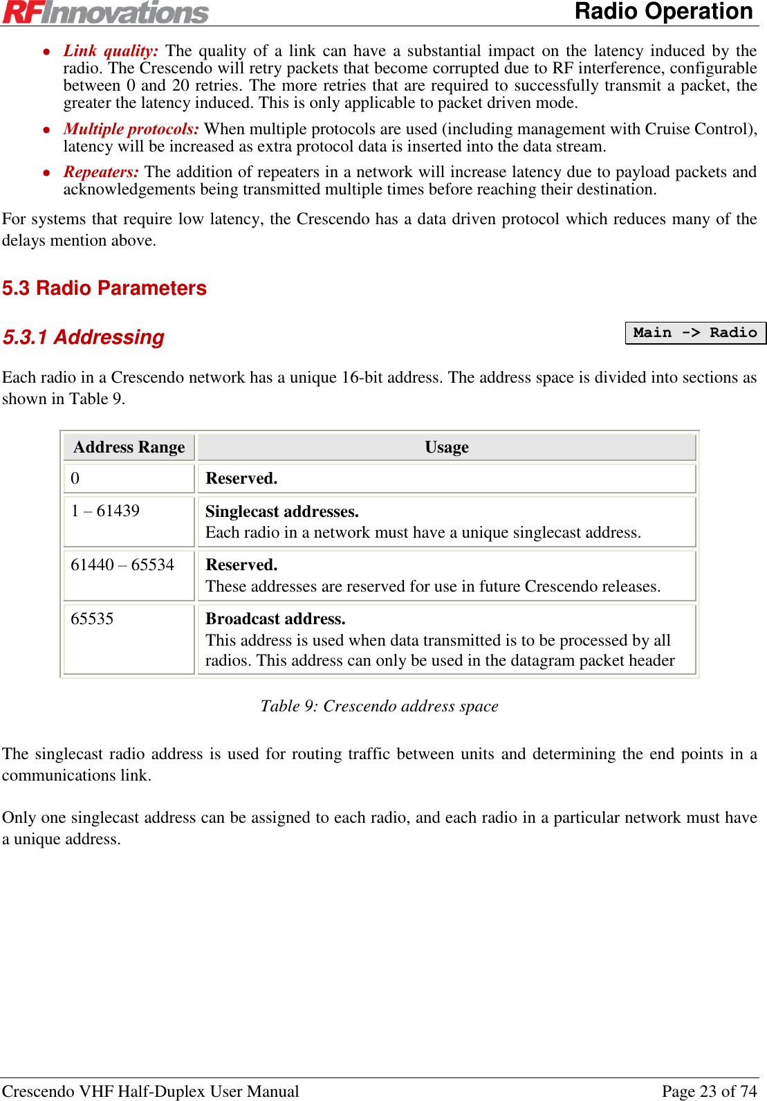
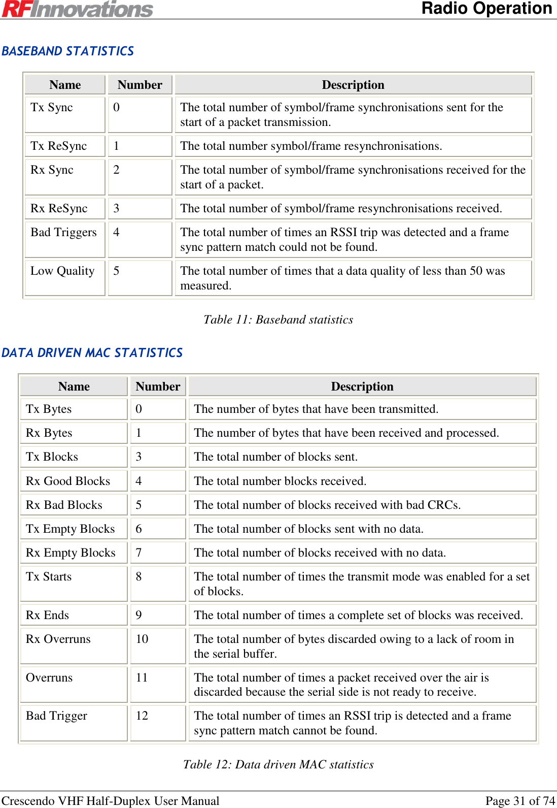
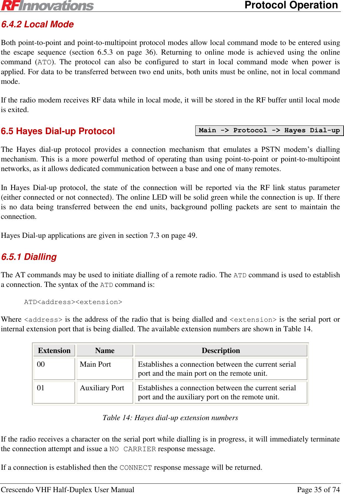
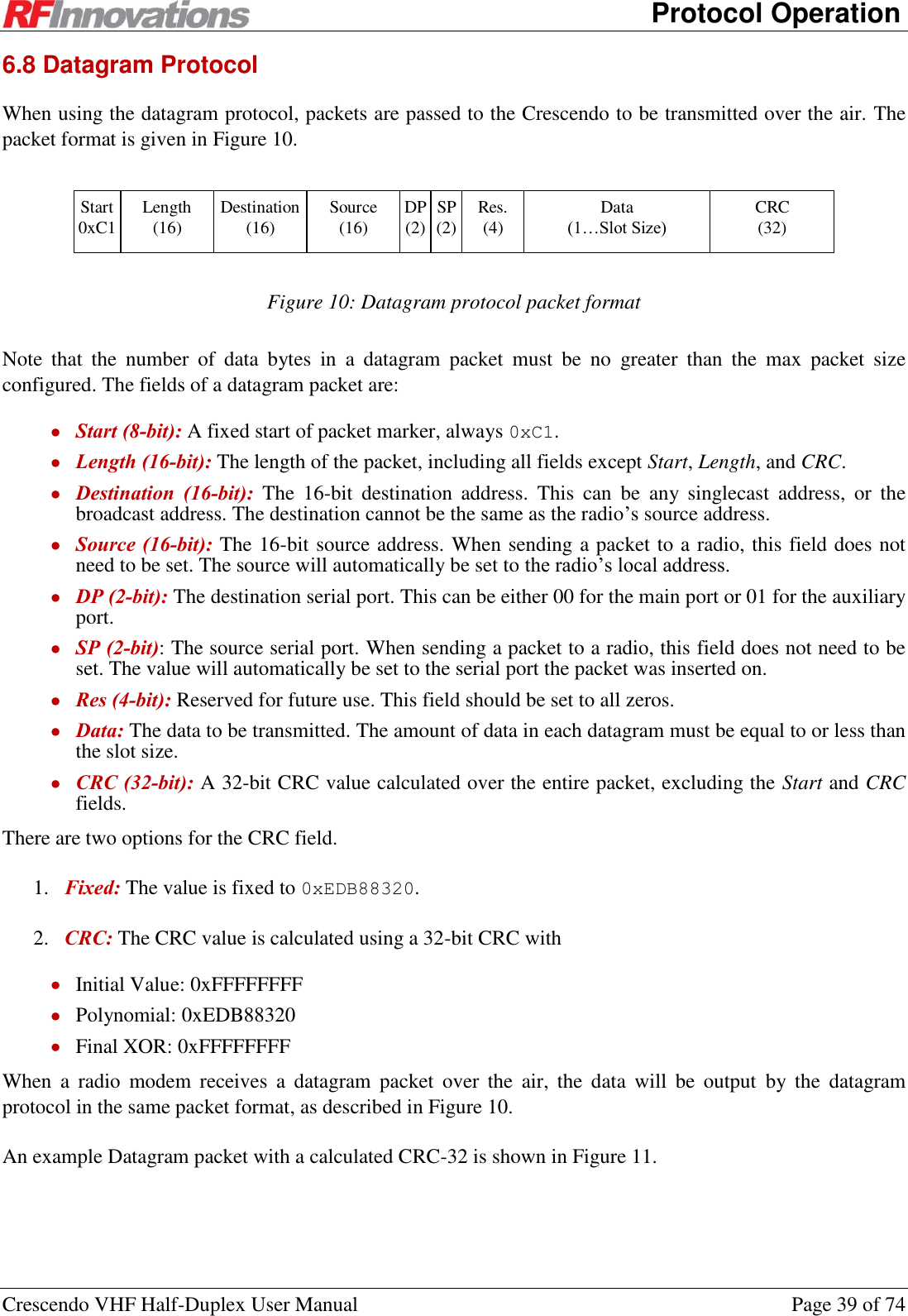
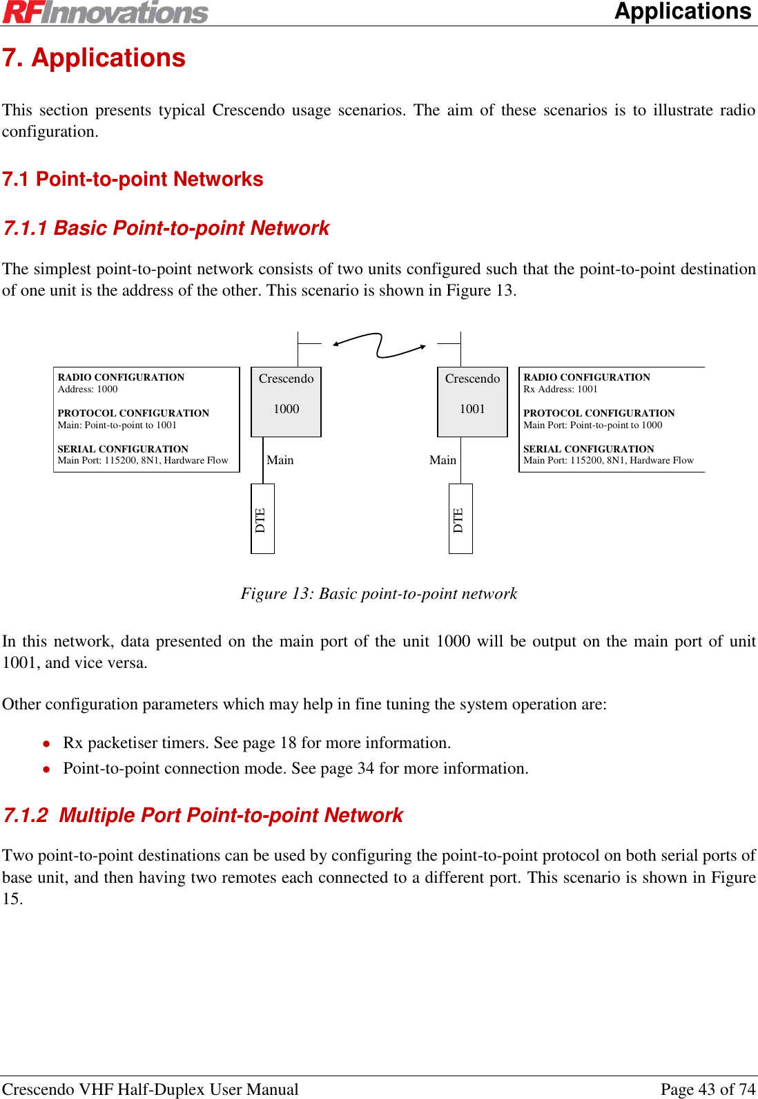
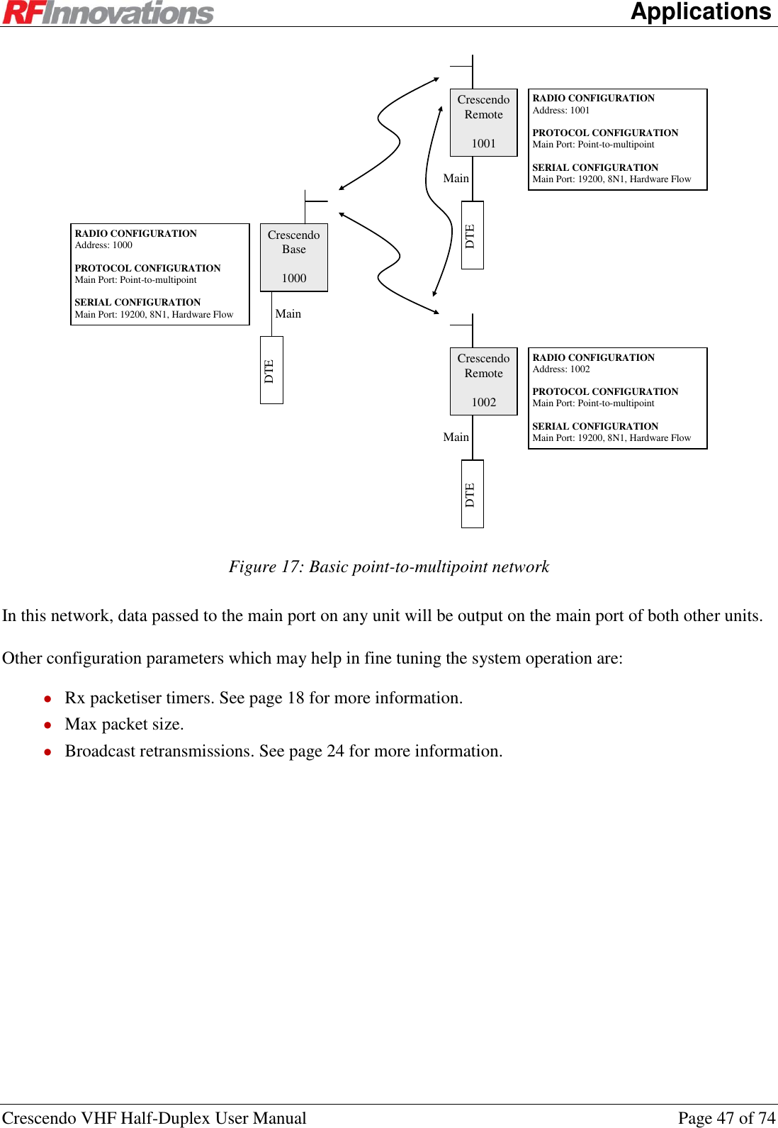
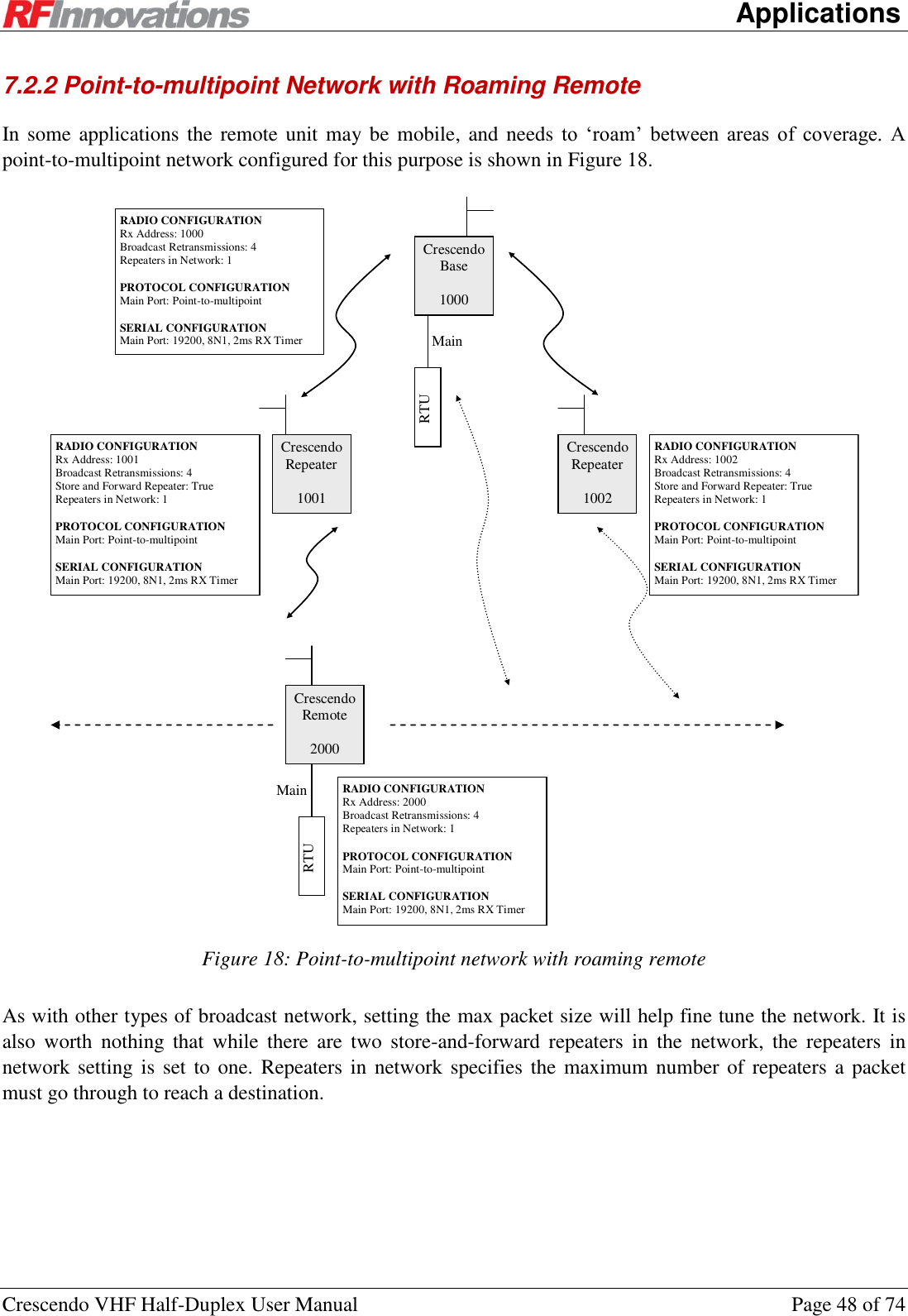
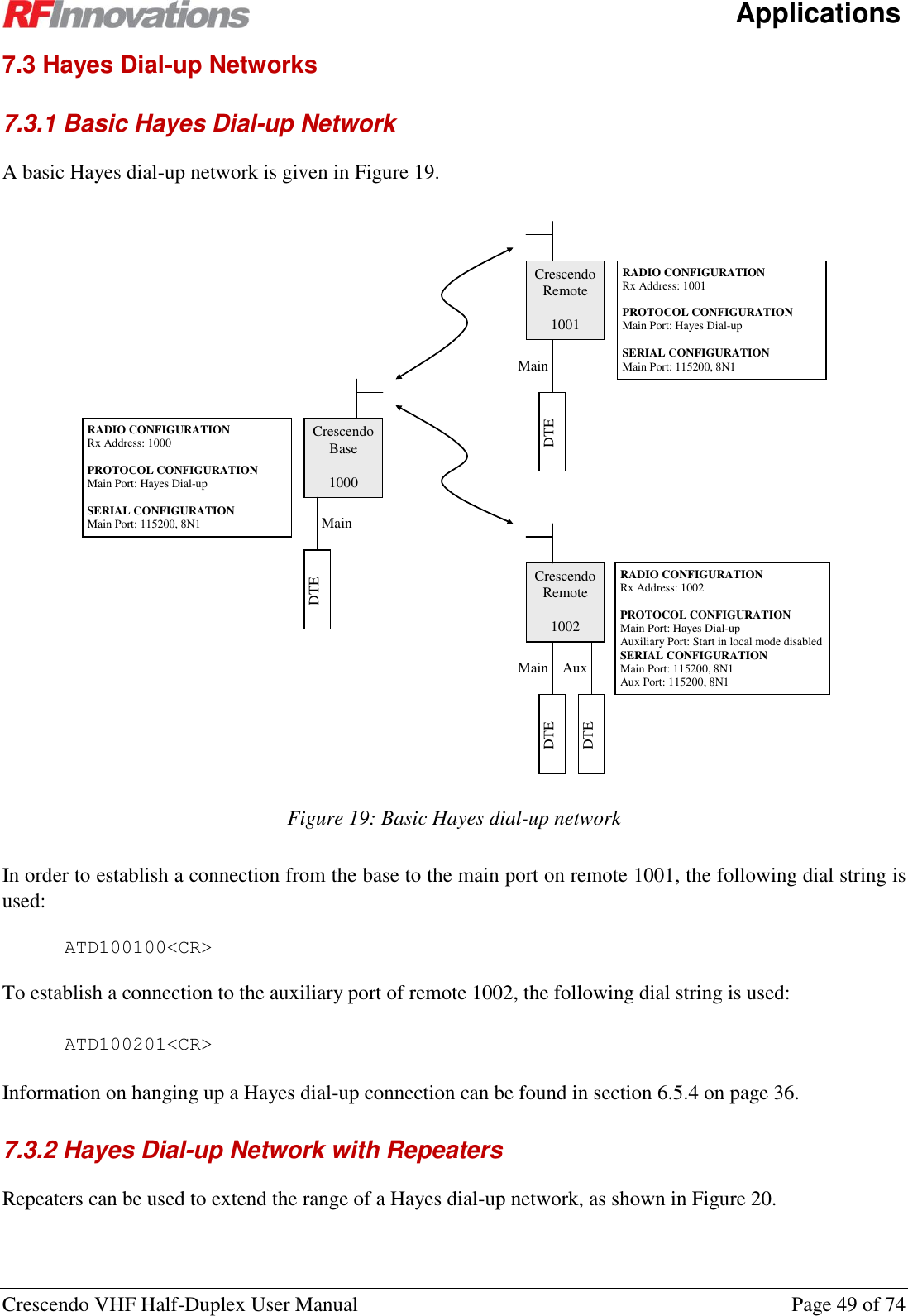
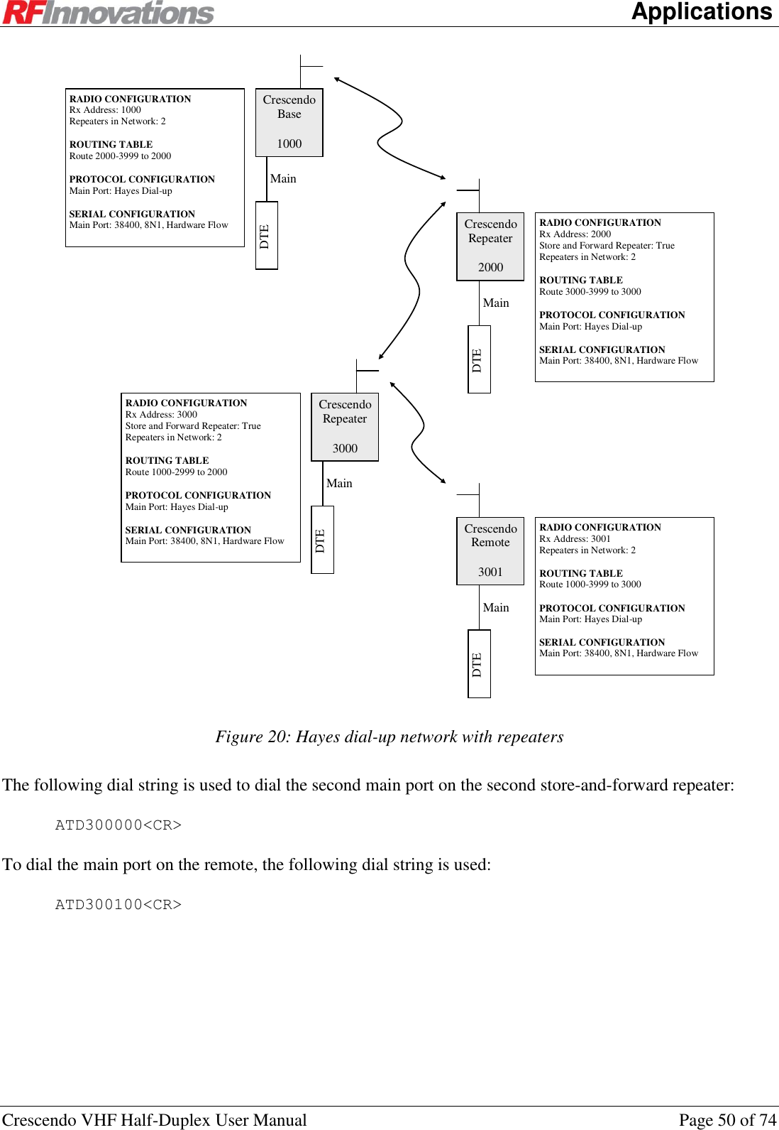
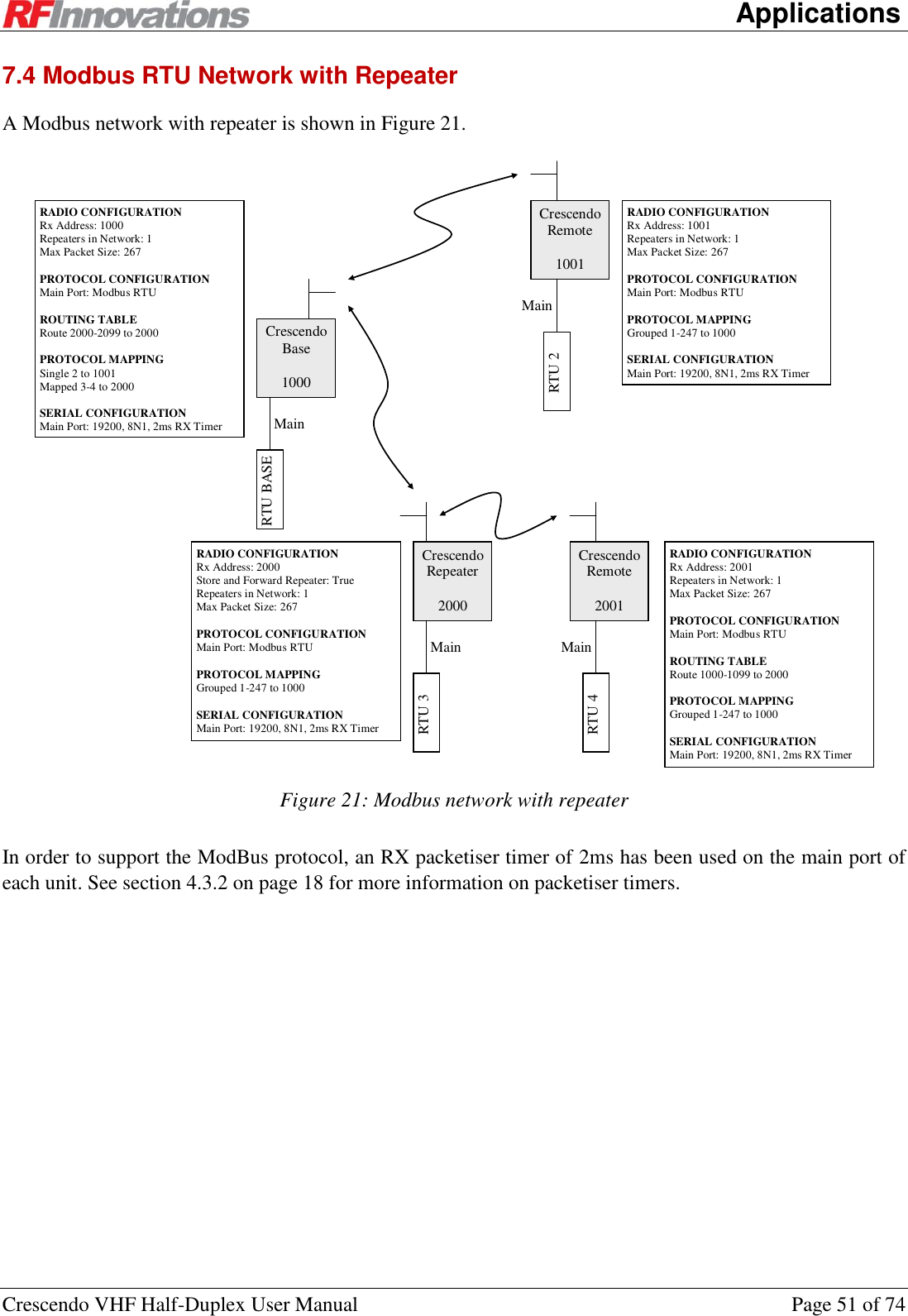
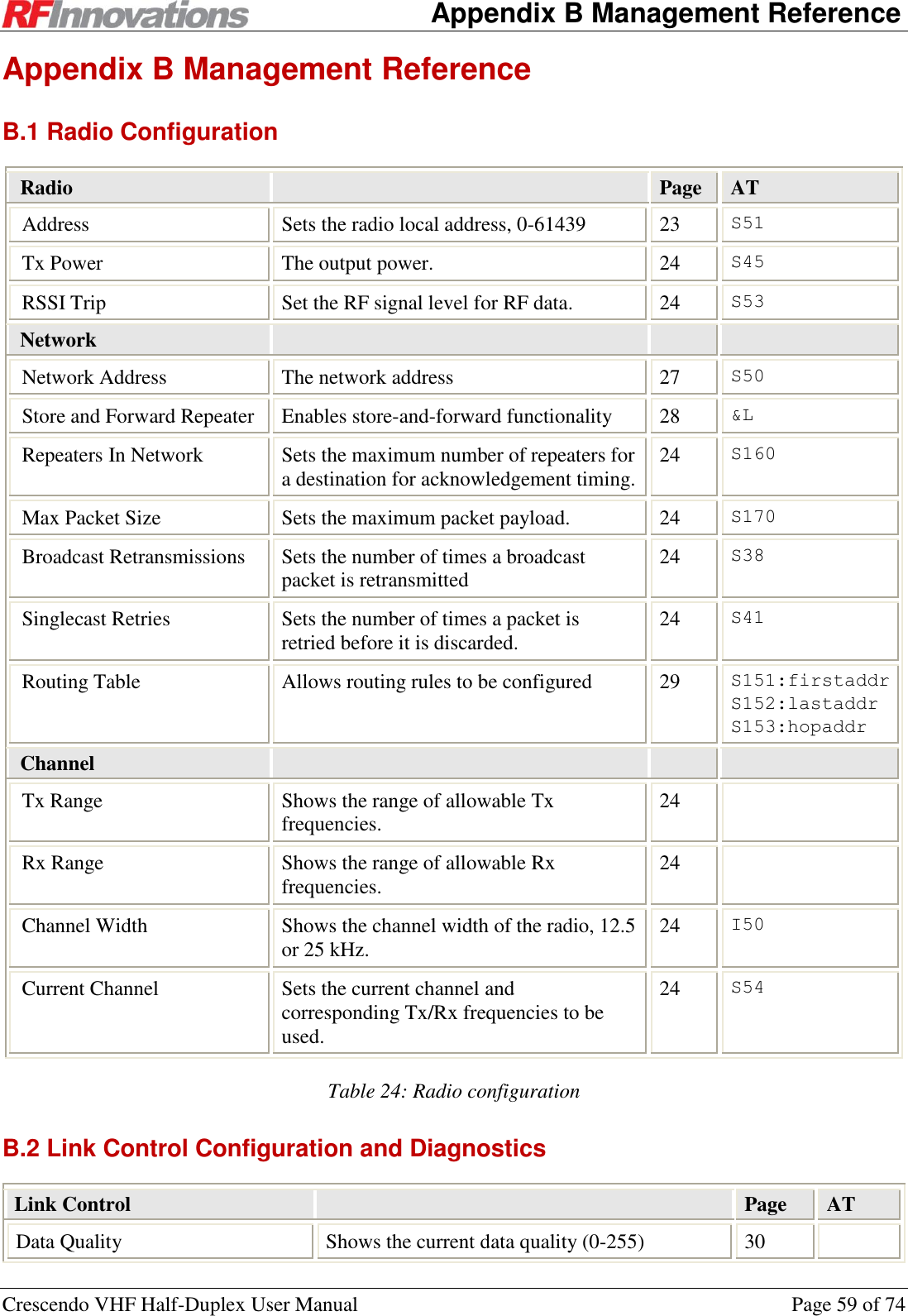
![Configuration Crescendo VHF Half-Duplex User Manual Page 12 of 74 3.4 Hayes AT Command Interface The Crescendo radio supports Hayes ATtention commands. These are used to query radio configuration and performance parameters, set radio configuration, and establish communication links between radios over the air. For a port to accept AT commands it must be first in local command mode. See section 6.5.3 on page 36 for information on enabling and disabling local command mode. The format for the query and configuration AT command is: ATxxx<[I1, I2, … In]><=value><TERM> Where: AT is the attention code. All AT commands must be prefixed with AT. This is case insensitive, so At, aT, or at can also be used. xxx is the actual command. The list of valid AT commands is given in 0 on page 62. <[I1, I2, … In]> is an optional section that allows the specification of an index. Indexes are used to access one of an array of similar items. For example, the Crescendo radio has two serial ports which can both have different configurations. The command ATS52[0]=1004 set the point-to-point destination on the main port, while the command ATS52[1]=1004 will set the point-to-point destination on the auxiliary port. <=value> is an optional section that is used to set the value of a configuration parameter. If this section is omitted, then the value of the configuration parameter will be displayed. <TERM> is the terminator for the AT command. A terminator can consist of a carriage return (ASCII value 13D) or a carriage return followed by a line feed (ASCII value 10D). For each AT command that is issued a response is generated. The list of responses to AT commands is shown in Table 1. Response Code Response Number Description OK 0 Returned whenever a command is entered that is executed correctly. CONNECT 1 Returned whenever a connection is established with a remote unit. RING 2 Returned whenever this unit is dialled by a remote unit. NO CARRIER 3 Returned whenever a connection fails to be established, or is dropped while it is operating. ERROR 4 Returned whenever a command is invalid or could not be executed. BUSY 7 Returned whenever an attempt is made to dial a remote unit and that unit already has a connection established, or an attempt is made to enable the menu via AT? but the menu system is already enabled on the other serial port. NO ANSWER 8 Returned whenever an attempt is made to dial a remote unit, and that unit fails to answer. Table 1: AT command response codes](https://usermanual.wiki/STI-Engineering/RFI150H.users-manual/User-Guide-1801278-Page-12.png)
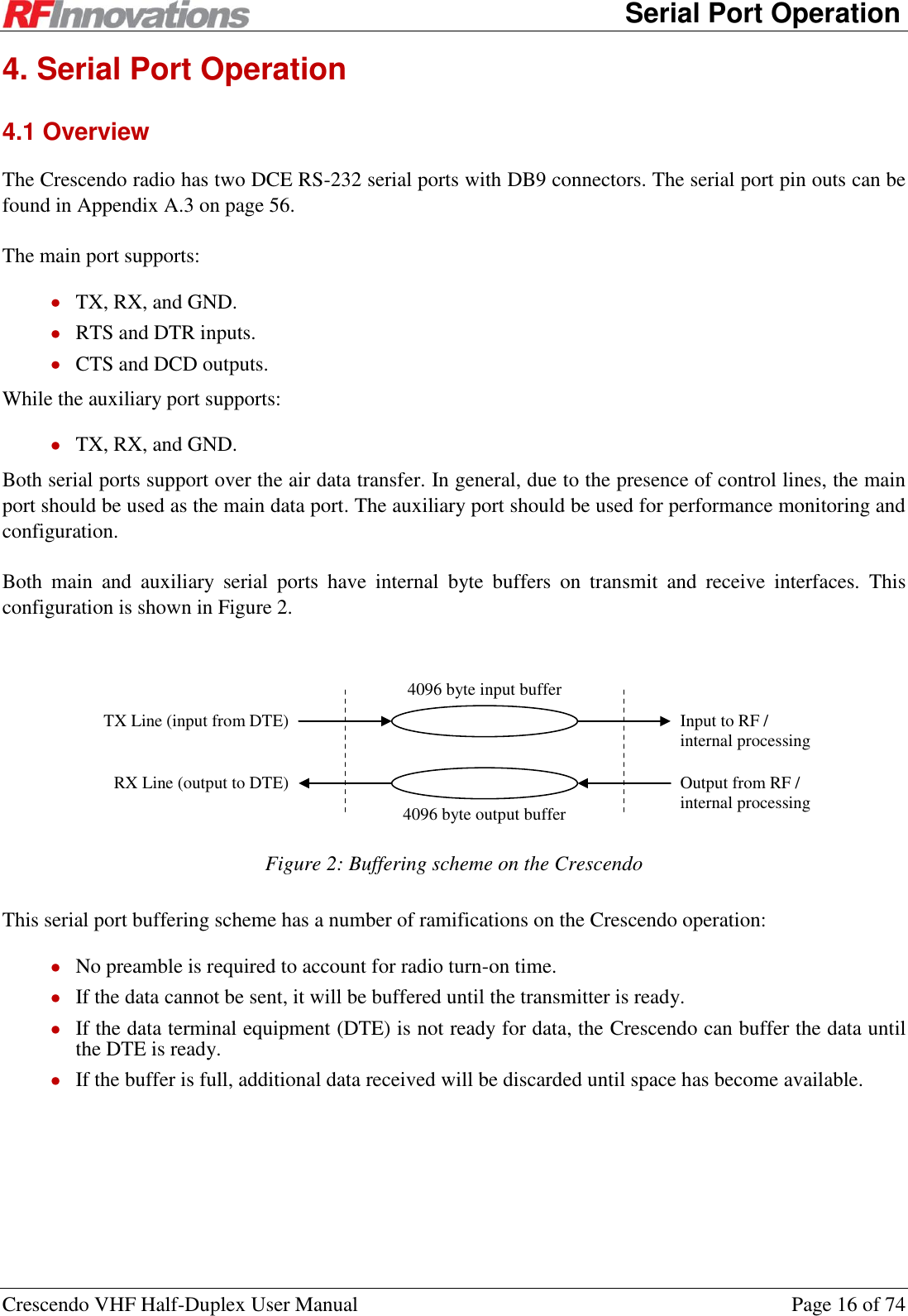
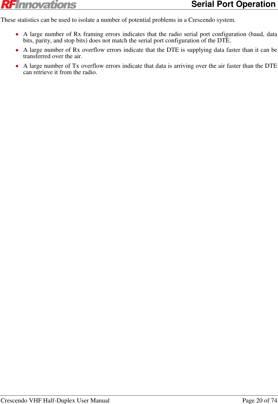
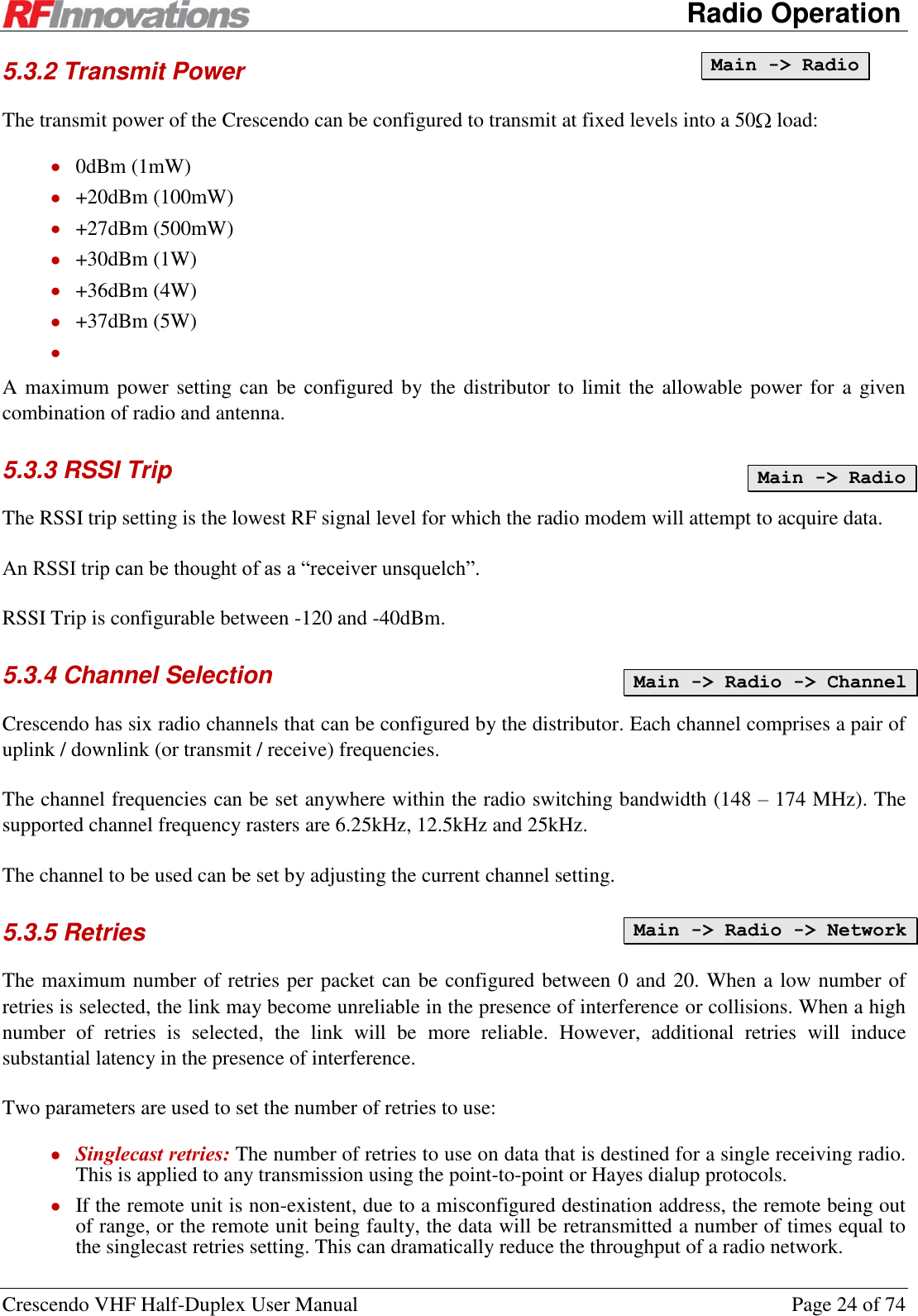
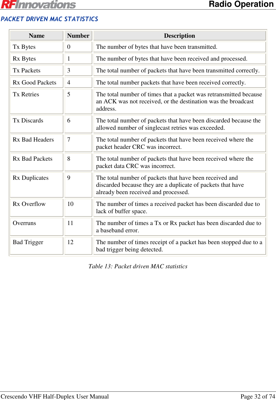
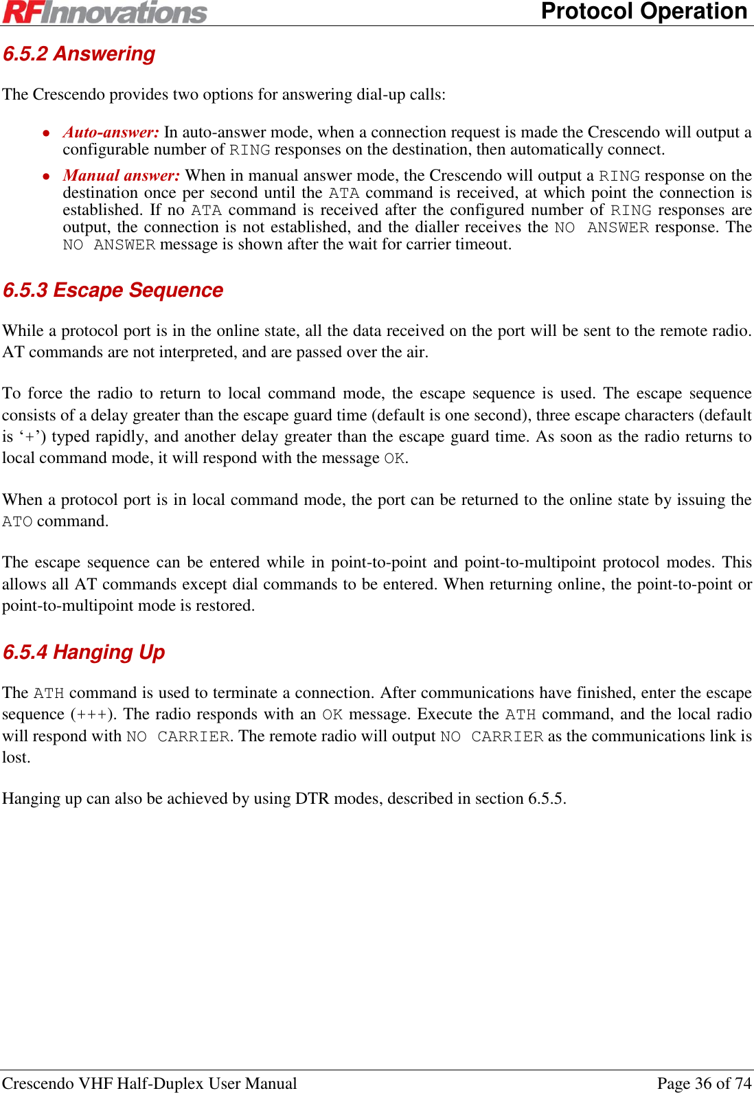
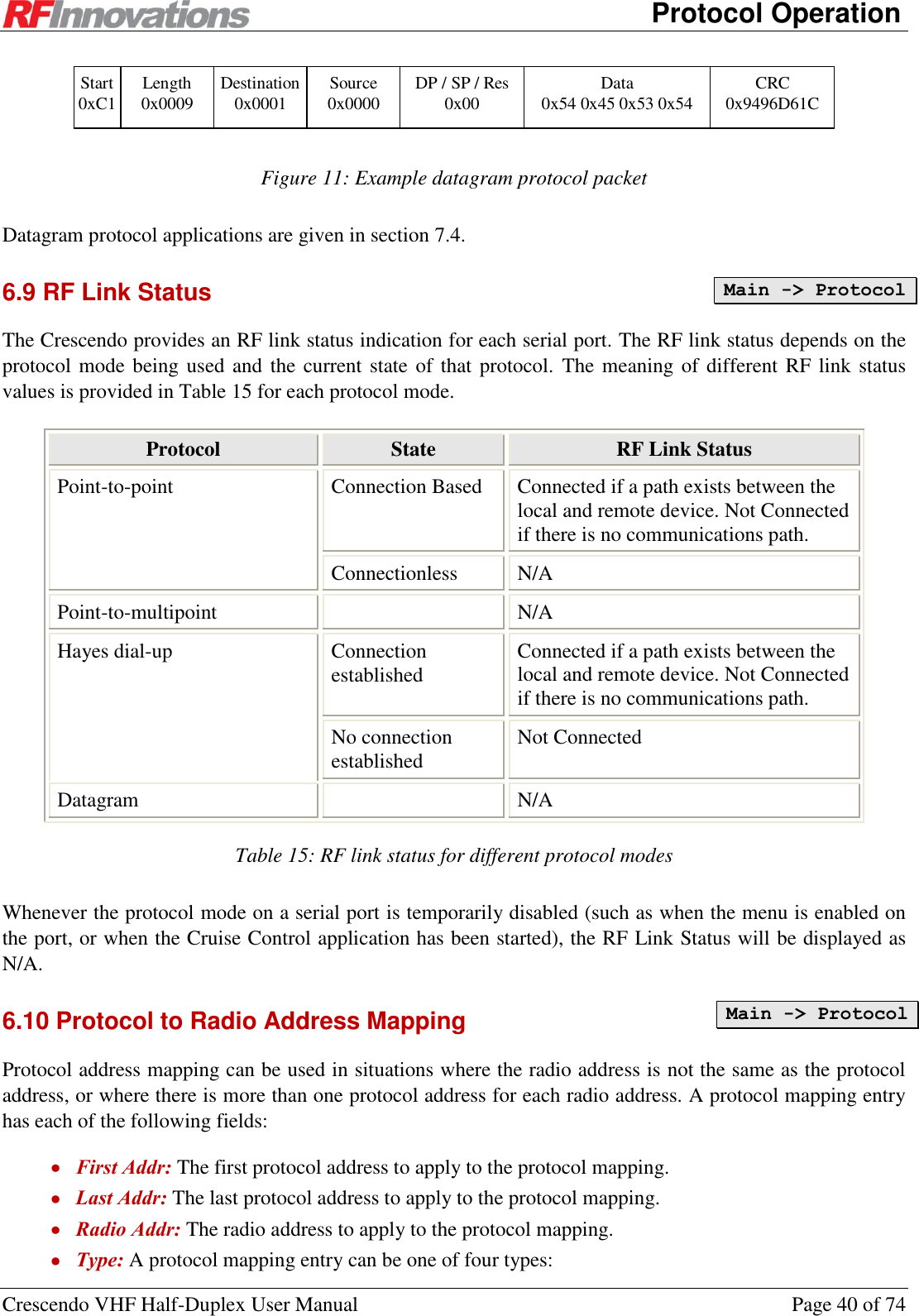
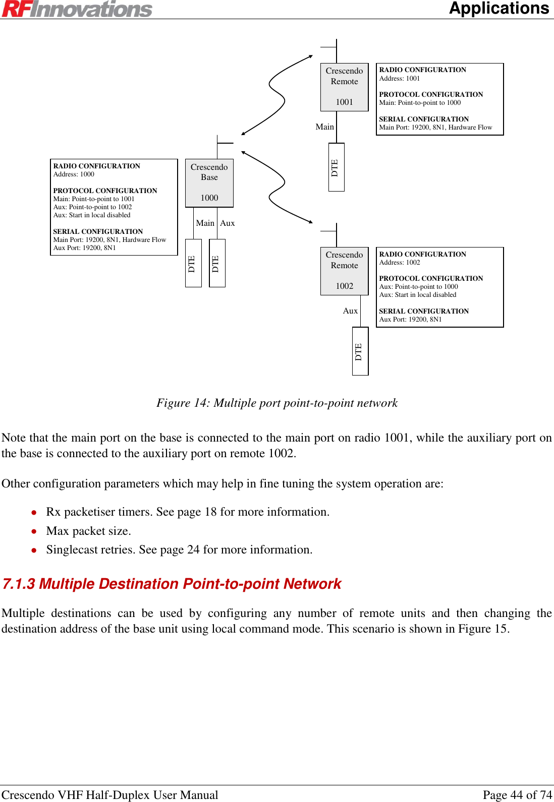
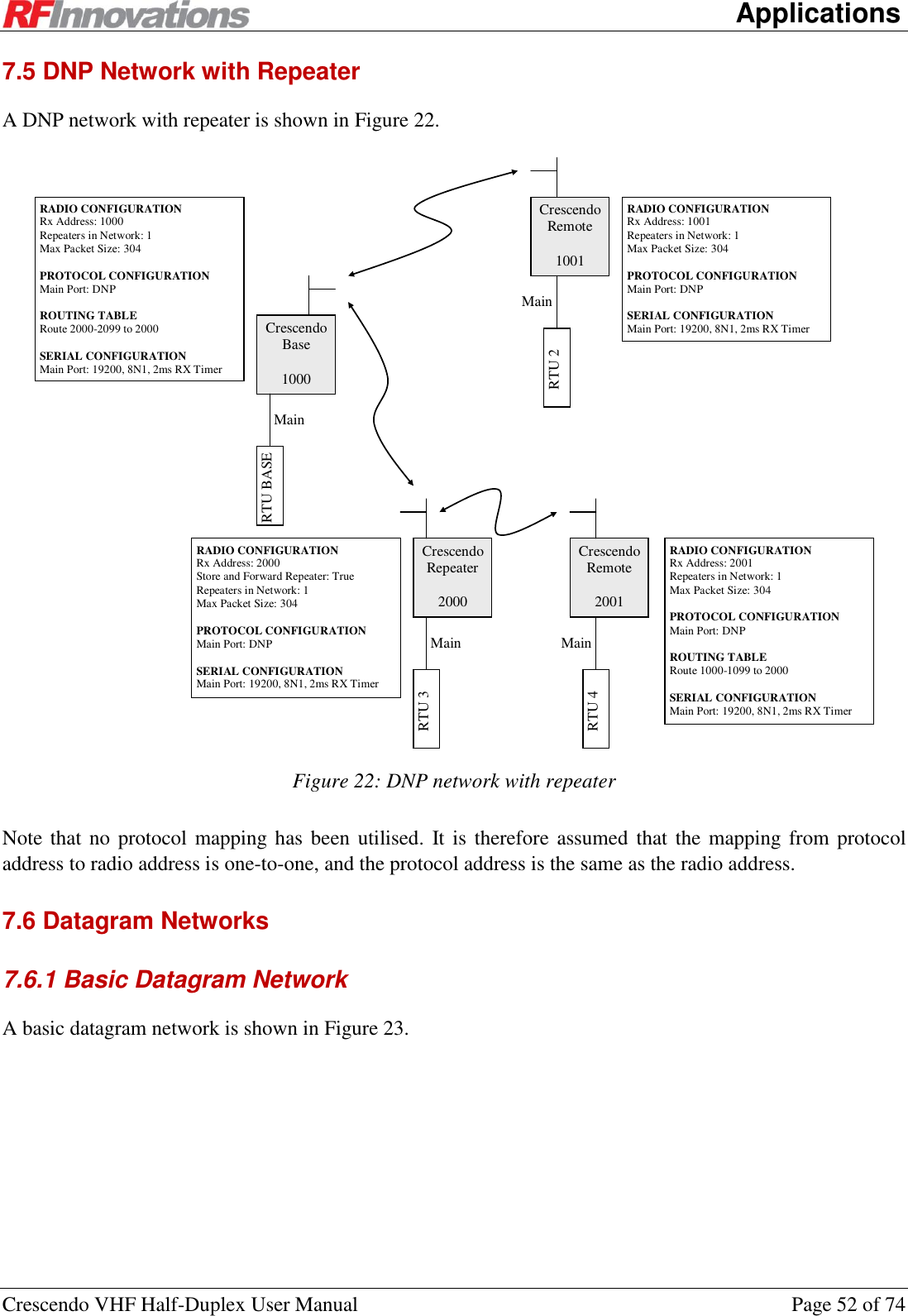
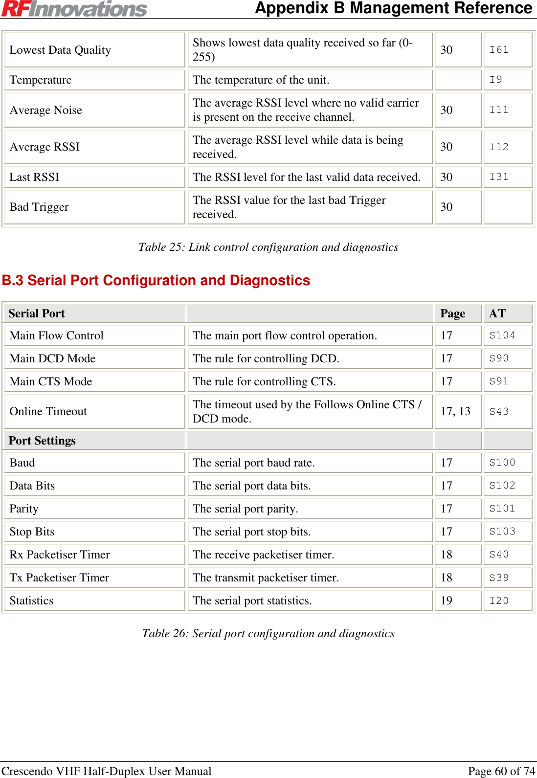
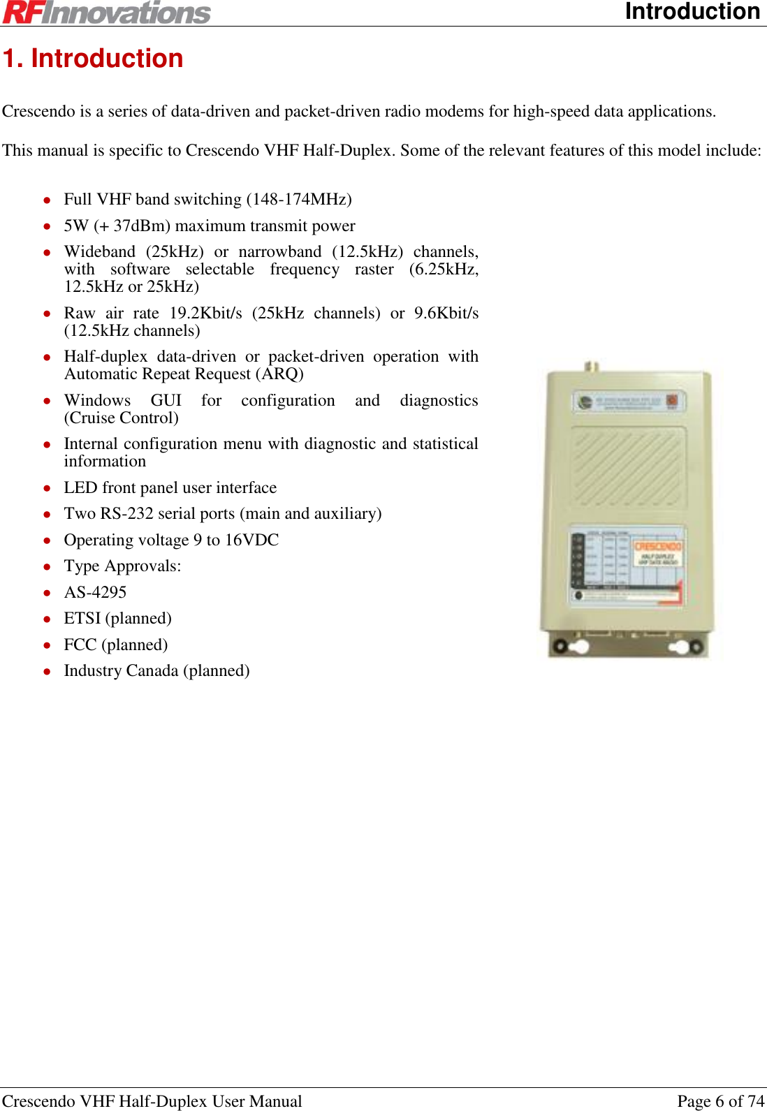
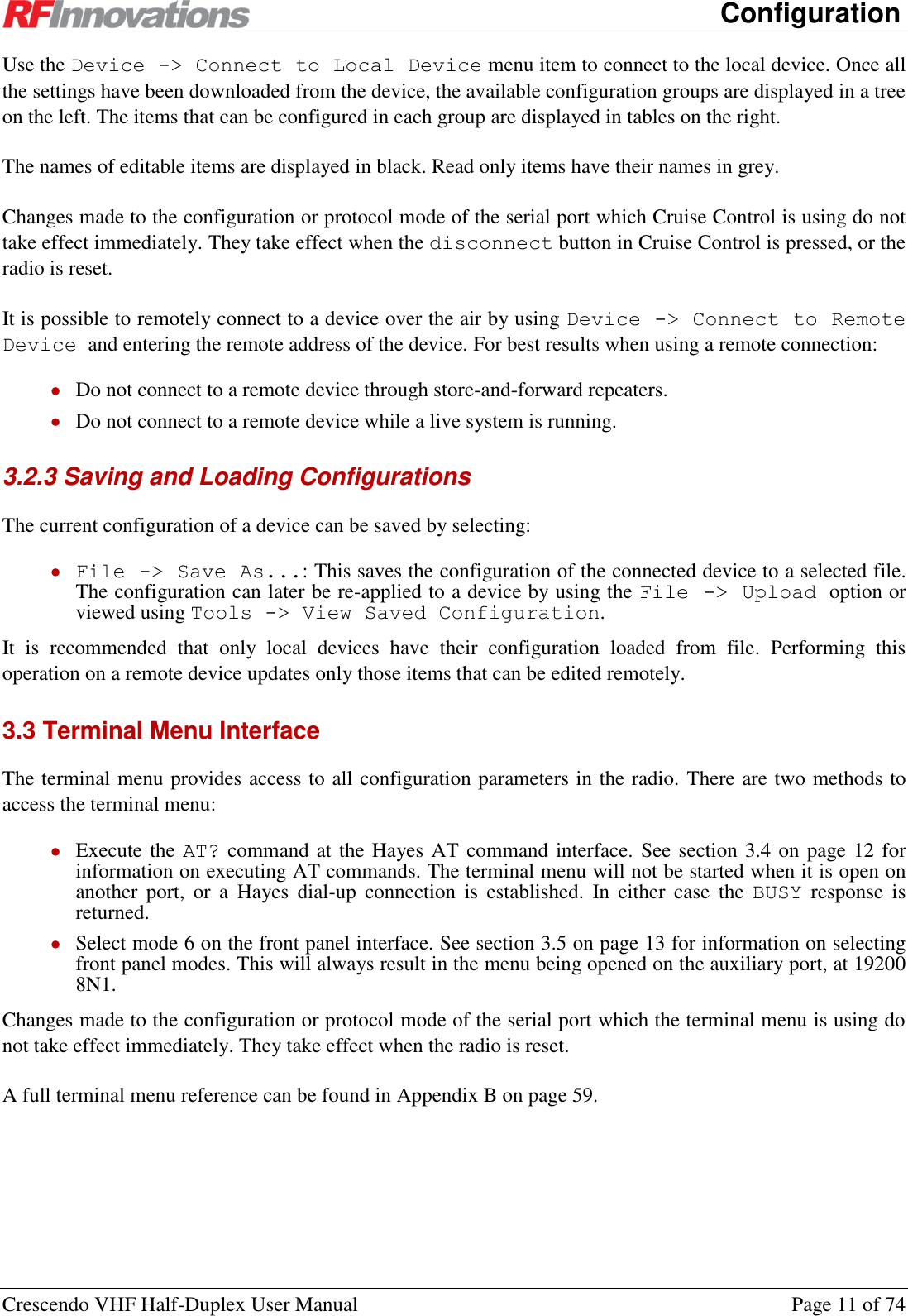
![Appendix B Management Reference Crescendo VHF Half-Duplex User Manual Page 61 of 74 B.4 Protocol Mode Configuration and Diagnostics Protocol Page AT Lead-in Count The number of lead-in bytes the radio will discard and not transmit over the air. 33 S73 Data timeout The period of serial silence the radio will wait before it stops transmitting. 33 S74 RF Link Status The state of the RF link for the port. 40, 34, 35 I16 Mode The selected protocol mode 33 S70 Point-to-point Destination Address The point-to-point partner radio address 34 S52 Start In Local Mode Enables local command mode on the port when the radio powers up. 35 S72 Point-to-Point Mode Connection or packet driven mode. 34 S71 Point-to-[multi]point Receive Mode The receive address mode (strict or relaxed). 34 S64 Hayes Dial-up Protocol Wait for Carrier Number of seconds to wait for a connection. 35 S7 Auto-Answer Whether to auto-answer dial requests. 36 S1 Rings Before Answer Number of rings to wait before auto-answering. 36 S0 DTR Mode Sets the action the radio takes on DTR settings. 37 &D Echo Whether to echo bytes in local command mode. 12 E Responses Enables or disables responses. 12 Q Verbal Responses Sets responses as either strings or numbers. 12 V Escape Guard Time Time to wait for the escape sequence. 35 S12 Escape Character The escape character. 35 S2 Allow Local Mode Enables usage of the escape sequence while in other protocol modes (excludes data driven). 35 S3 Datagram Protocol Footer Mode CRC-32 or fixed. 35 S140 Table 27: Protocol mode configuration and diagnostics](https://usermanual.wiki/STI-Engineering/RFI150H.users-manual/User-Guide-1801278-Page-61.png)
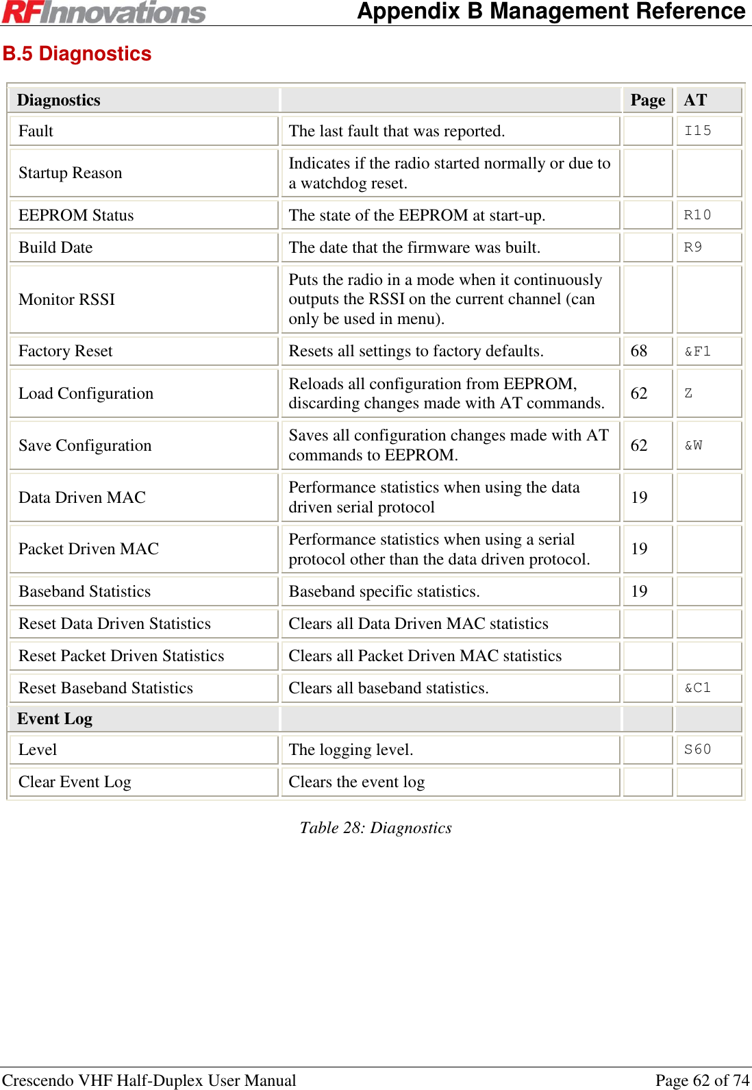
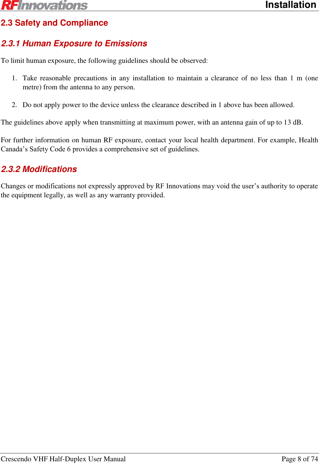
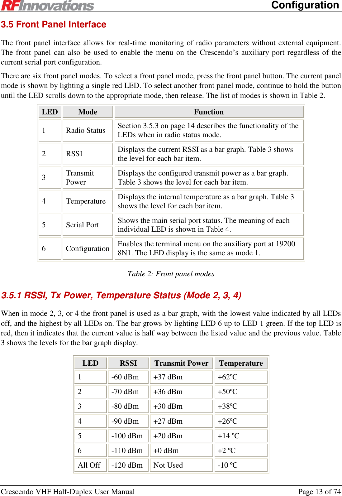
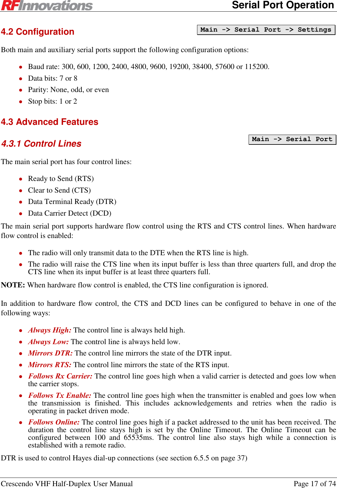
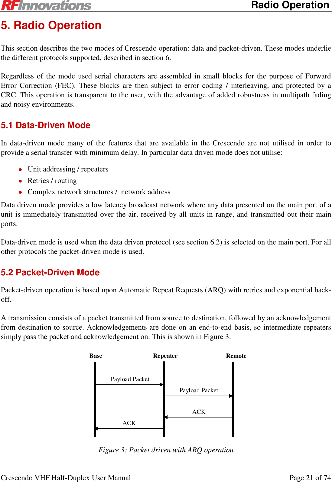
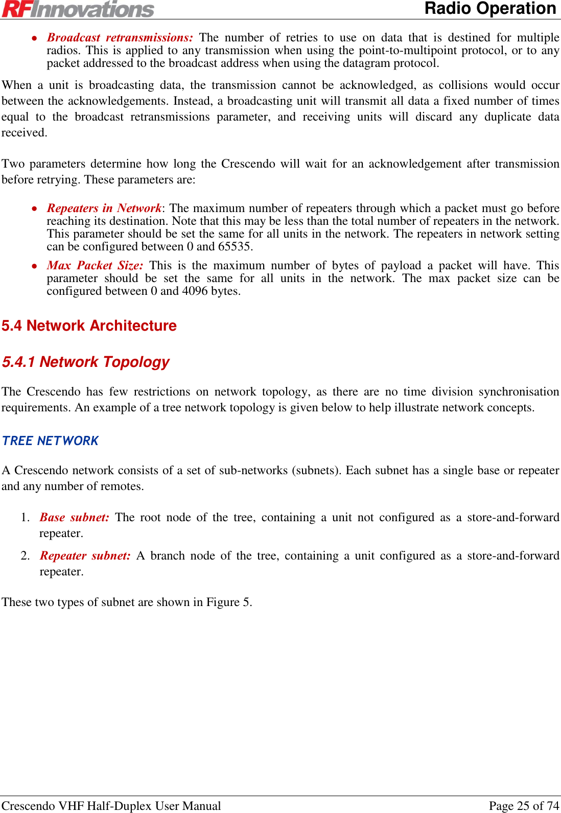
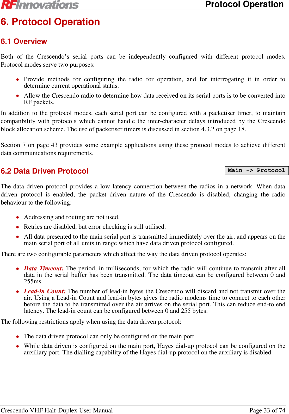
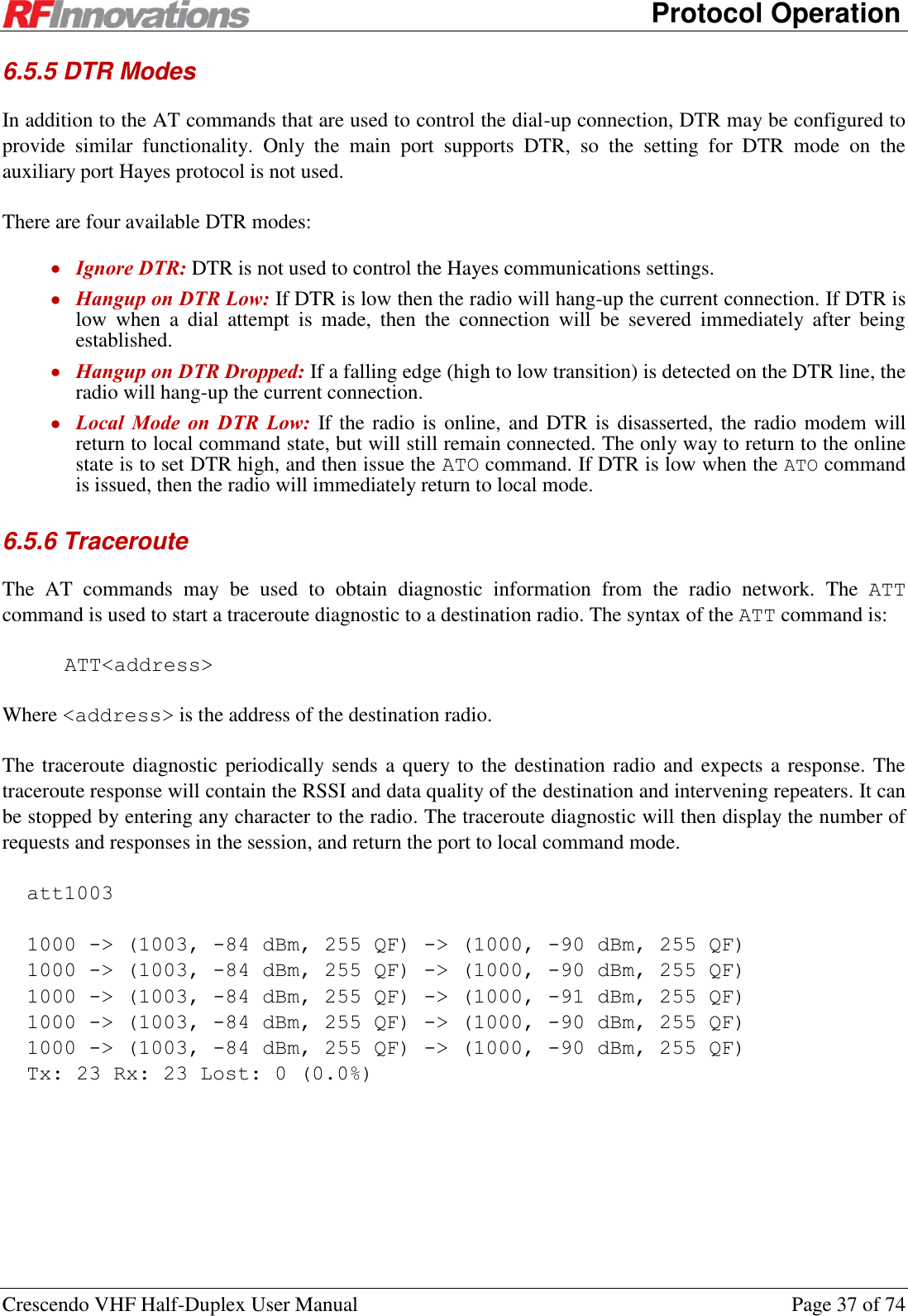
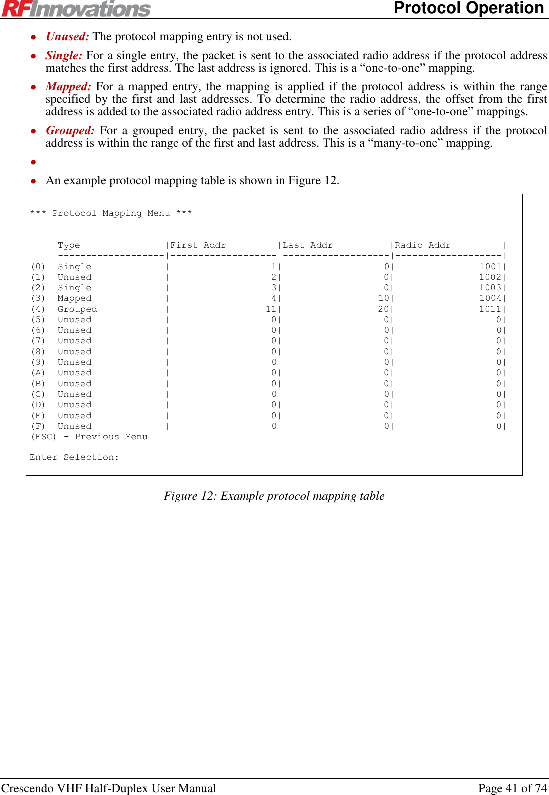
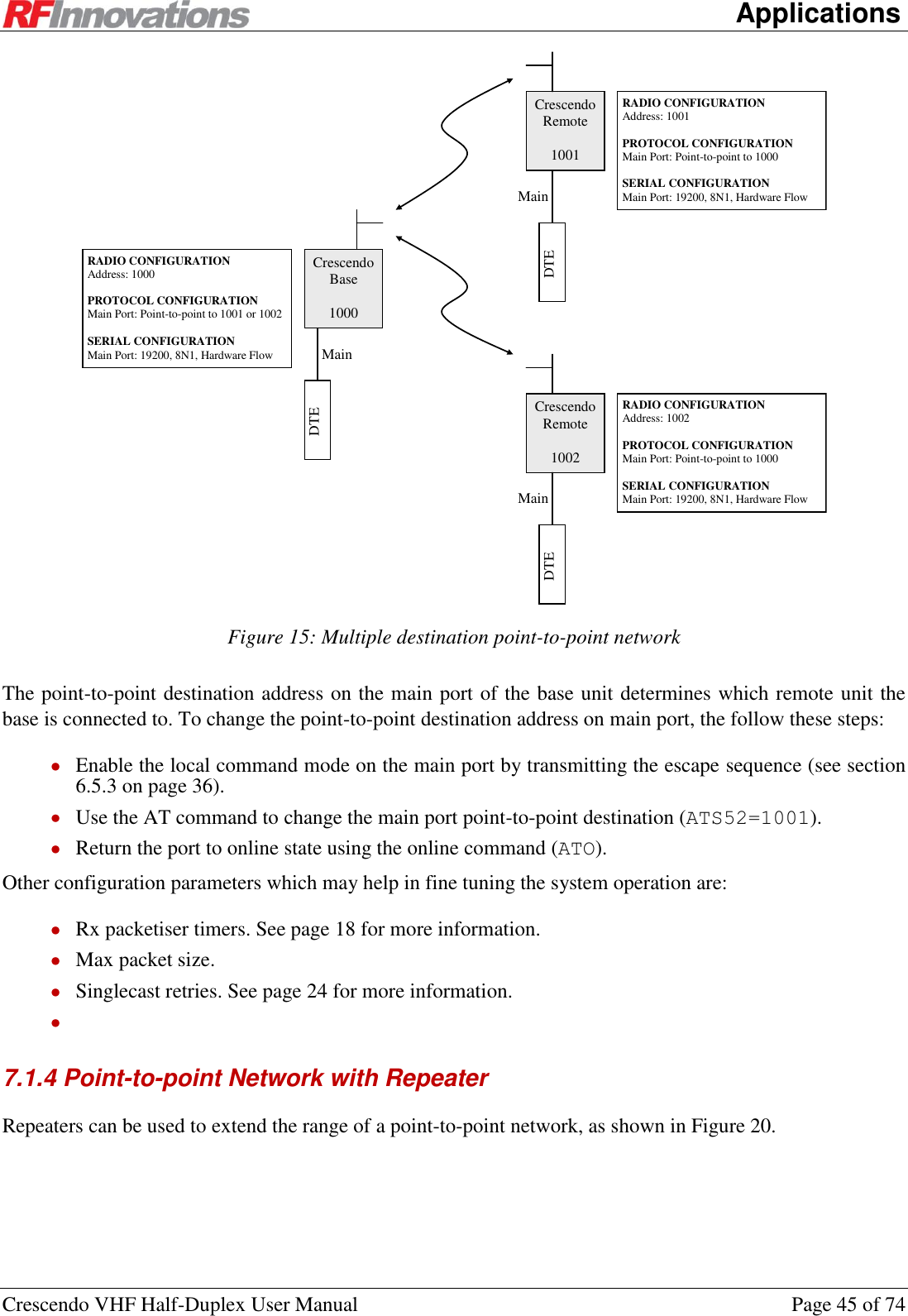
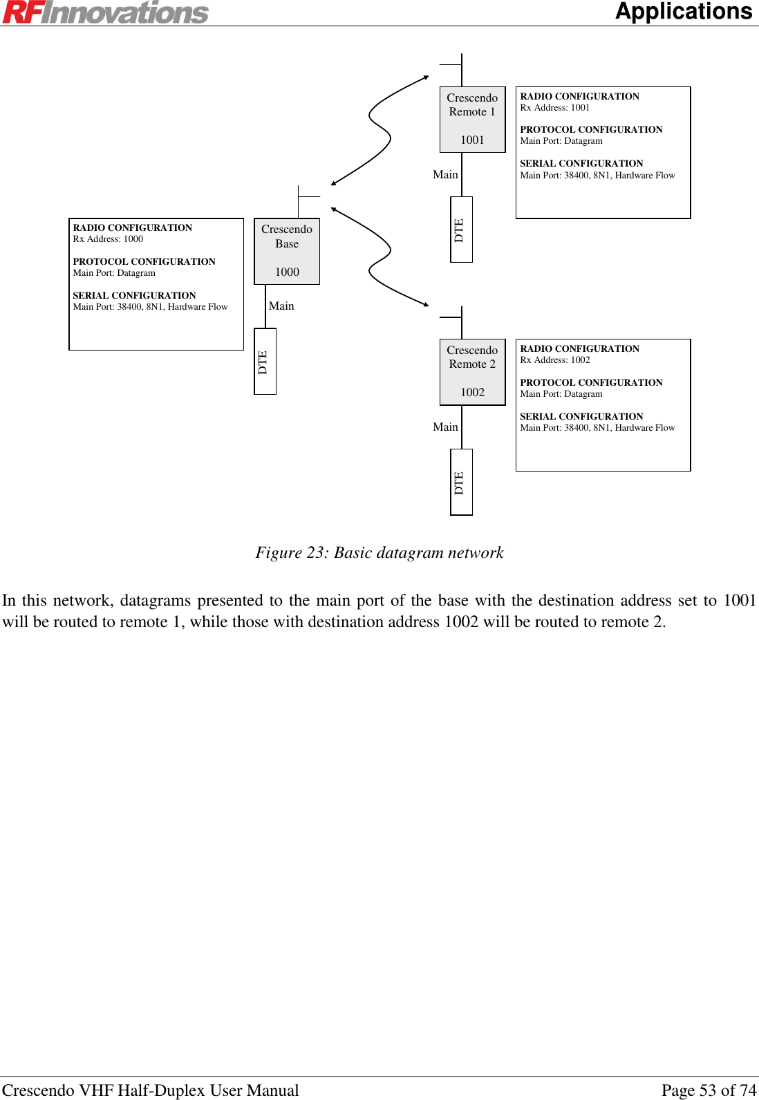
![Appendix C Hayes References Crescendo VHF Half-Duplex User Manual Page 64 of 74 AT&V1 View All I Registers AT&V2 View All S Registers AT&W Save Configuration Saves the current configuration to EEPROM. AT? Enable Menu AT%30 Enable Cruise Control Enables the Cruise Control on the serial port. Wait for 10 seconds after executing with no further data input to return to normal Hayes mode. Table 29: Hayes general commands C.2 Connection Management Commands Command Name Notes ATT Traceroute Starts a traceroute diagnostic to a destination radio. See section 6.5.6. ATD ATDT ATDP Dial ATA Answer ATH ATH0 Hangup ATO ATO0 Go Online Table 30: Hayes connection management commands C.3 I-Registers Command Name Notes ATI5 Manufacture Date ATI6 Serial Number ATI9 Temperature ATI11 Average RSSI ATI15 Fault ATI16[0] RF Link Status Returns the RF link status for the main port. ATI16[1] Returns the RF link status for the auxiliary port. ATI20[p, s] Serial Port Statistics](https://usermanual.wiki/STI-Engineering/RFI150H.users-manual/User-Guide-1801278-Page-64.png)
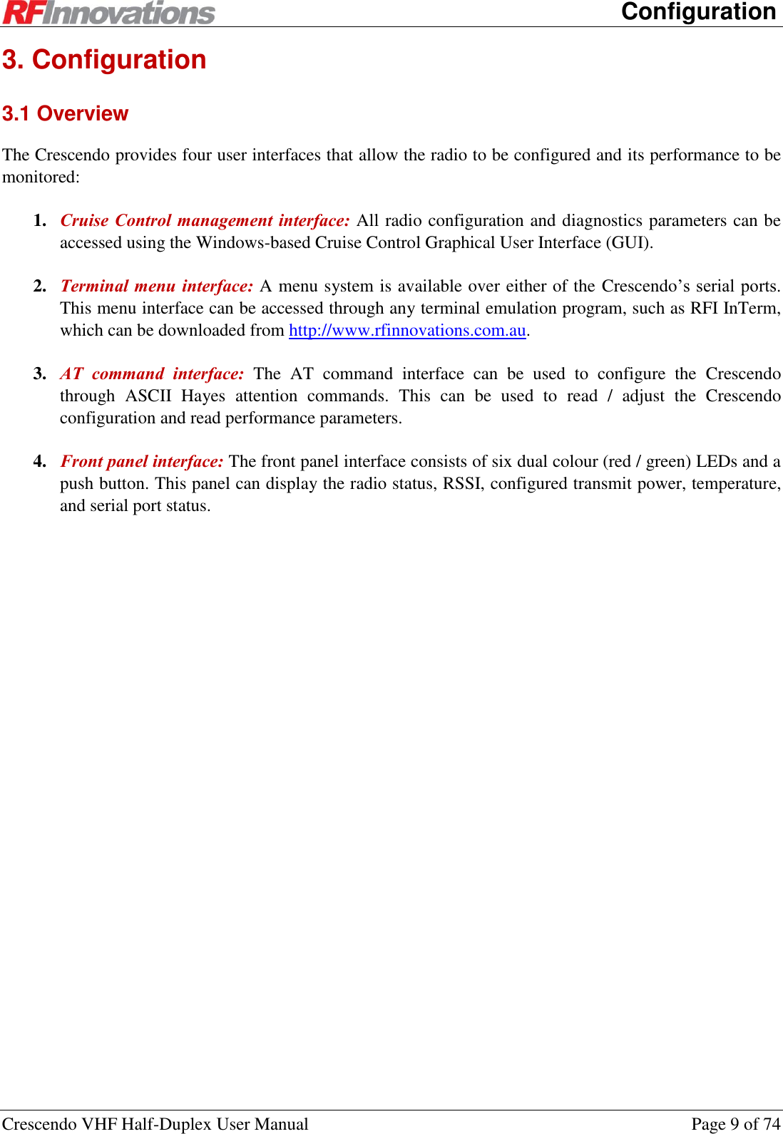
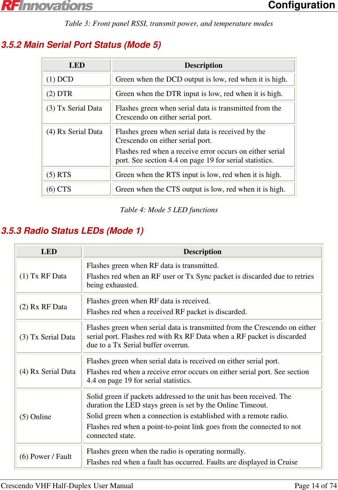
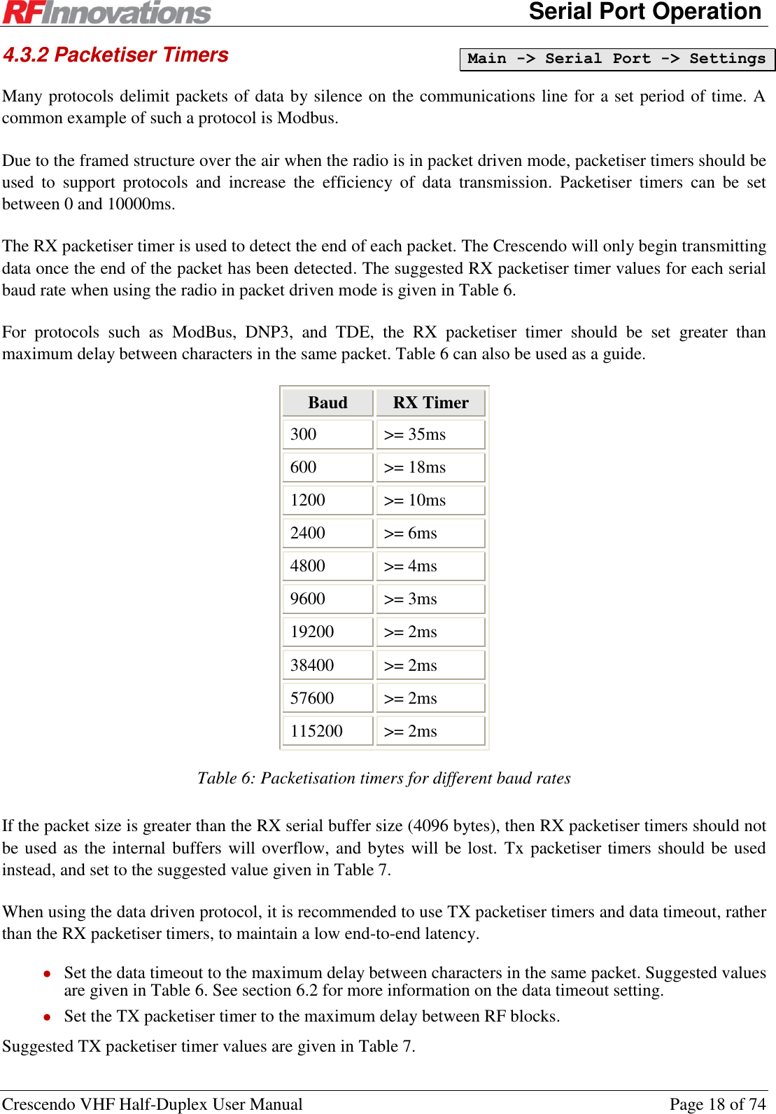
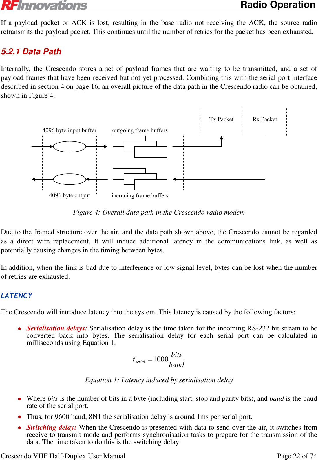
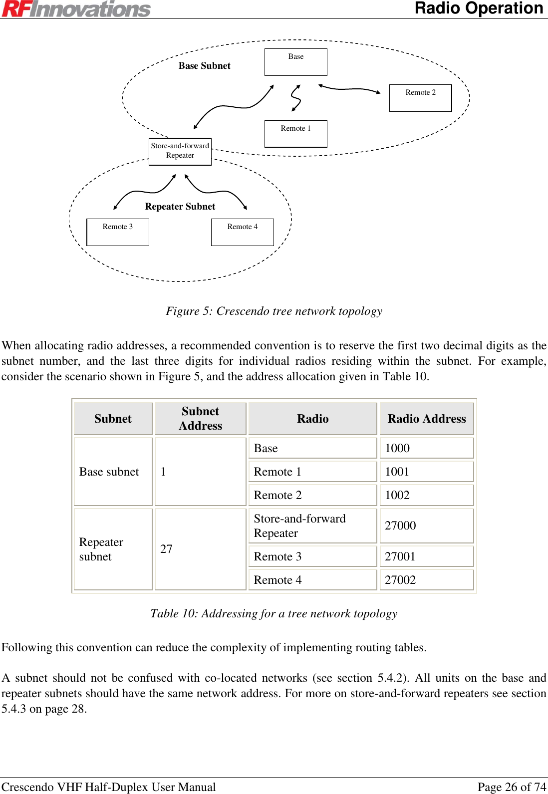
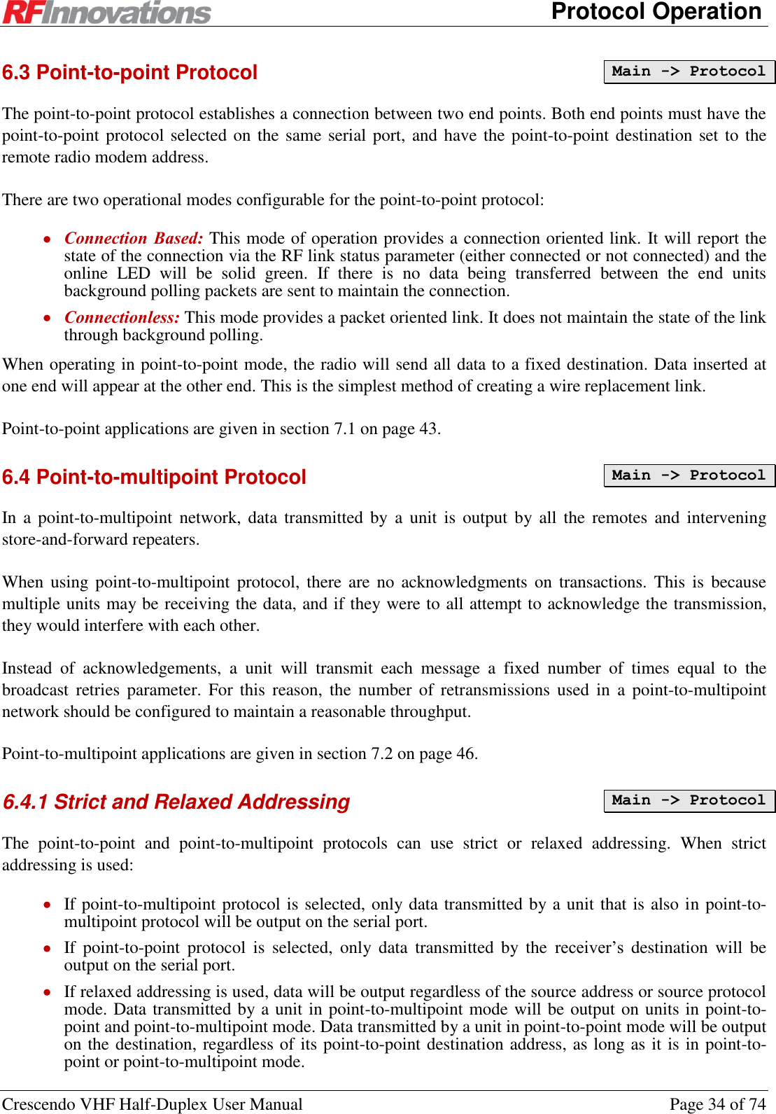
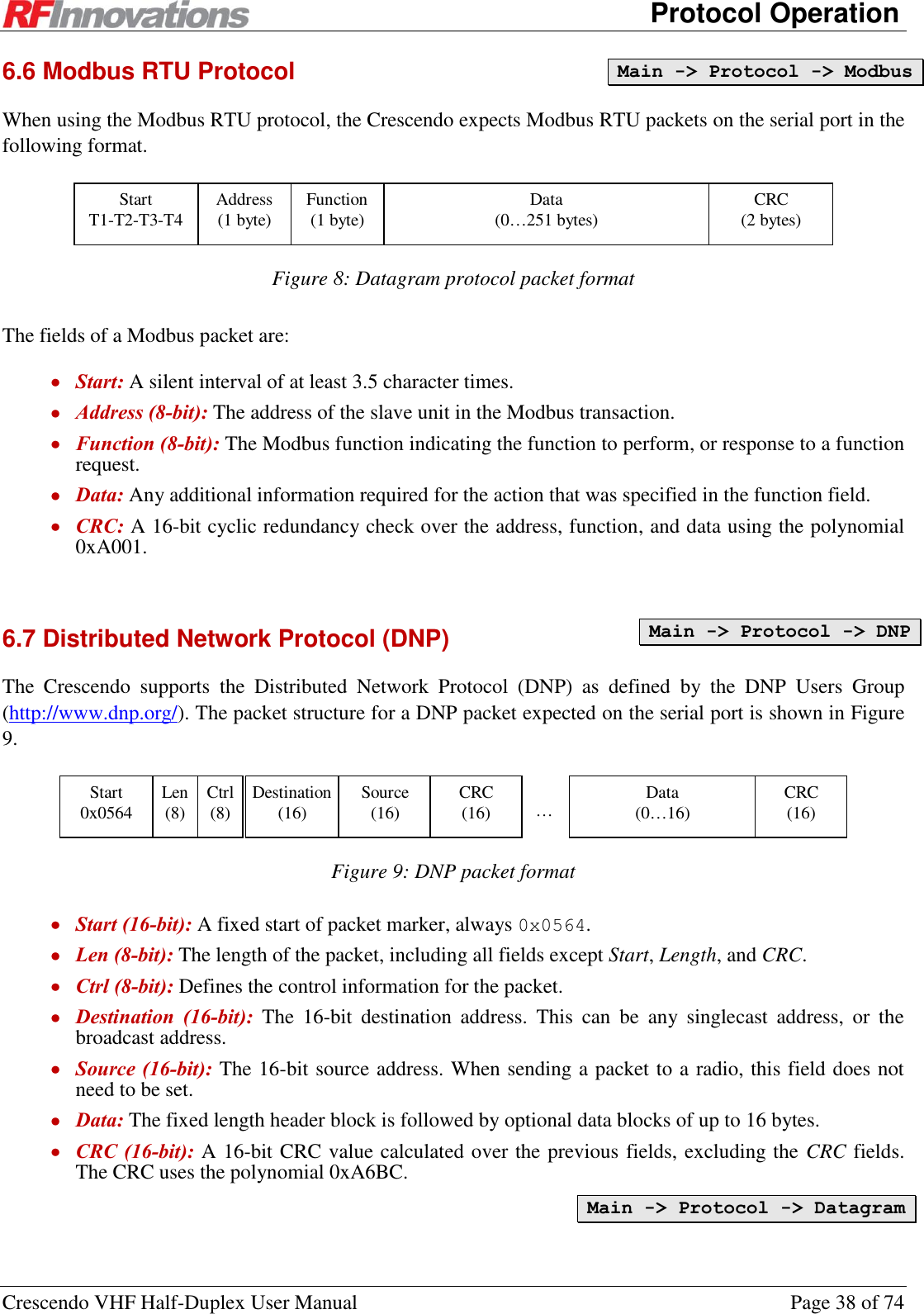
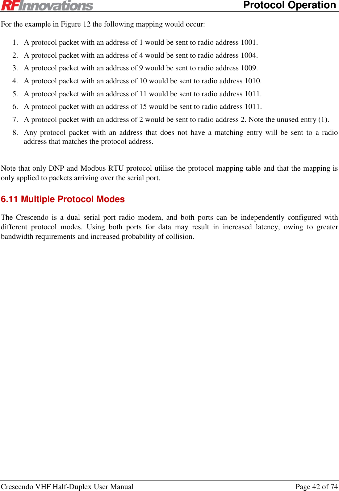
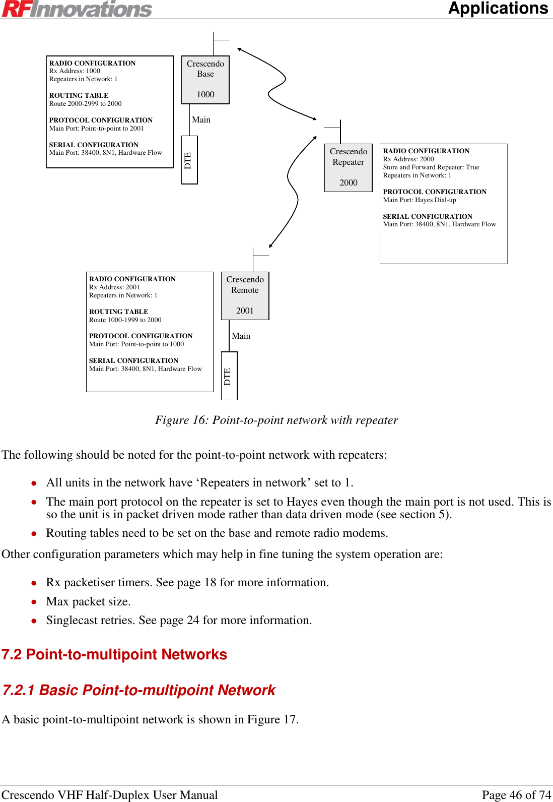
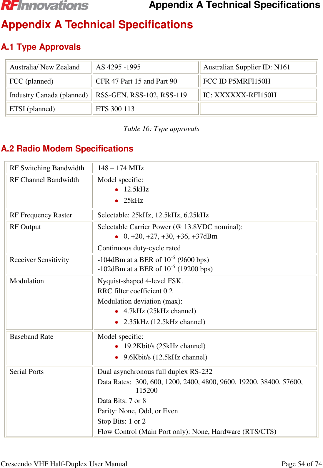
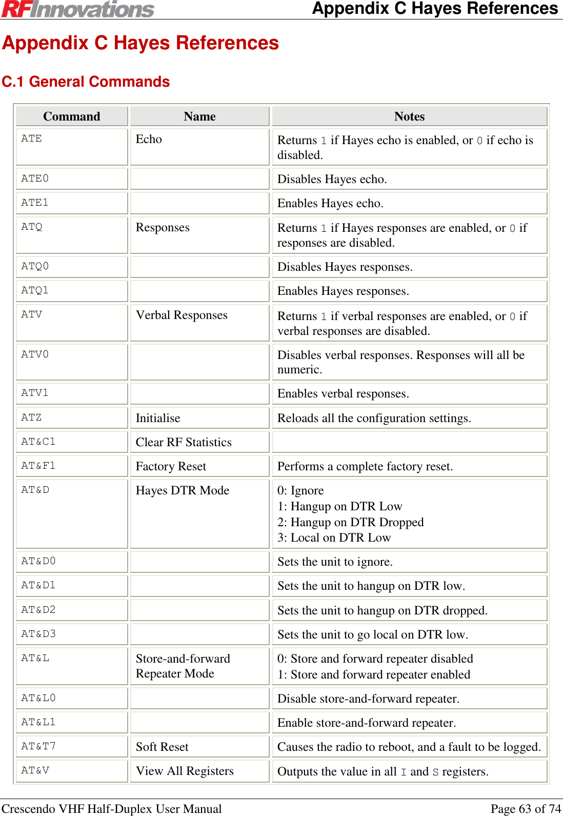
![Appendix C Hayes References Crescendo VHF Half-Duplex User Manual Page 65 of 74 ATI25[s] Get Baseband Statistic ATI26[s] Get Data Driven MAC Statistic ATI27[s] Get Packet Driven MAC Statistic ATI50 Channel Width Table 31: Hayes I-register commands C.4 S-Registers All serial port configuration and status commands can be executed on either the main port or auxiliary port. The parameter [p] that may be passed to each serial port AT command should be set to 0 for main, or 1 for auxiliary. Command Name Notes ATS0 Rings Before Answer Sets or returns the current number of rings before auto-answer. ATS1 Auto Answer 0: Disabled 1: Enabled ATS2 Escape Character Sets or returns the current escape character. ATS7 Wait for Carrier Sets or returns the number of seconds to wait for a carrier to be established. ATS12 Escape Guard Time Sets or returns the escape guard time in ms. ATS38 Broadcast Retransmissions ATS39 Tx Packetiser Timer ATS40 Rx Packetiser Timer ATS41 Singlecast Retries ATS45 Transmit Power 0: 0 dBm 1: +20 dBm 2: +27 dBm 3: +30 dBm 4: +36 dBm 5: +37 dBm ATS50 Network Address ATS51 Radio Address](https://usermanual.wiki/STI-Engineering/RFI150H.users-manual/User-Guide-1801278-Page-65.png)
![Appendix C Hayes References Crescendo VHF Half-Duplex User Manual Page 66 of 74 Command Name Notes ATS52 Point-to-point Destination Address ATS53 RSSI Trip ATS54 Current Channel ATS60 Log Filter 0: Faults 1: Warnings 2: Status 3: Information 4: Debugging ATS64 Point-to-[multi]point Receive Addressing 0: Strict 1: Relaxed ATS70 Protocol Mode 0: Point-to-point 1: Point-to-multipoint 2: Hayes Dial-up 3: Datagram 4: Log ATS71 Point-to-point Mode 0: Connectionless 1: Connection Based ATS90 Main Port DCD Mode This command cannot have a [p] port specifier. 0: Always High 1: Always Low 2: Mirrors DTR 3: Mirrors RTS 4: Follows Rx Carrier 5: Follows Tx Enable 6: Follows Online ATS91 Main Port CTS Mode This command cannot have a [p] port specifier. 0: Always High 1: Always Low 2: Mirrors DTR 3: Mirrors RTS 4: Follows Rx Carrier 5: Follows Tx Enable 6: Follows Online ATS92 Get Main Port DTR This command cannot have a [p] port specifier. 0: Line is not asserted. 1: Line is asserted.](https://usermanual.wiki/STI-Engineering/RFI150H.users-manual/User-Guide-1801278-Page-66.png)
![Appendix C Hayes References Crescendo VHF Half-Duplex User Manual Page 67 of 74 Command Name Notes ATS93 Get Main Port RTS Mode This command cannot have a [p] port specifier. 0: Line is not asserted. 1: Line is asserted. ATS100 Baud 0: 110 1: 300 2: 600 3: 1200 4: 2400 5: 4800 6: 9600 7: 14400 8: 19200 9: 38400 ATS101 Parity 0: None 1: Even 2: Odd ATS102 Data Bits 0: 7 1: 8 ATS103 Stop Bits 0: 1 1: 2 ATS104 Main Port Flow Control This command cannot have a [p] port specifier. 0: None 2: Hardware (RTS / CTS) ATS140 Datagram Footer Mode 0: Fixed 1: CRC-32 ATS151[a] Routing Table Entry First Address ATS152[a] Routing Table Entry Last Address ATS153[a] Routing Table Hop Address ATS160 Repeaters in Network ATS170 Max RF Packet Size Table 32: Hayes S-register commands](https://usermanual.wiki/STI-Engineering/RFI150H.users-manual/User-Guide-1801278-Page-67.png)
![Index Crescendo VHF Half-Duplex User Manual Page 73 of 74 Index Addressing.......................................................................... 23 Answering .......................................................................... 36 Applications ....................................................................... 43 AT Commands ................................................................... 12 Auto-answer ....................................................................... 36 Broadcast retransmissions .................................................. 25 Button ................................................................................. 13 Channel Selection ............................................................... 24 Configuration ....................................................................... 9 Connection Based ............................................................... 34 Connectionless ................................................................... 34 Cruise Control .................................................................... 10 Data timeout ....................................................................... 61 Datagram Protocol........................................................ 38, 39 Basic Network ............................................................... 52 Diagnostics ......................................................................... 62 Dialling ............................................................................... 35 DTR Modes ........................................................................ 37 Escape Sequence ................................................................ 36 Factory Defaults ................................................................. 69 Fault ................................................................................... 14 Front Panel ......................................................................... 13 Glossary.............................................................................. 72 GUI ..................................................................................... 10 Hanging Up ........................................................................ 36 Hayes AT Commands .................................................. 12, 63 Connections ................................................................... 64 General .......................................................................... 63 I-Registers ..................................................................... 64 R-Registers .................................................................... 68 S-Registers ..................................................................... 65 Hayes Dial-up Protocol ...................................................... 35 Basic Network ............................................................... 49 Repeater Network .................................................... 45, 49 Hopping Pattern ................................................................. 27 Installation ............................................................................ 7 Introduction .......................................................................... 6 Latency ............................................................................... 22 Lead-in Count ..................................................................... 61 LEDs .................................................................................. 13 Local Mode ........................................................................ 35 Main Serial Port Status ....................................................... 14 Management Reference Address .......................................................................... 59 Auto-Answer ................................................................. 61 Average Noise ............................................................... 60 Average RSSI ................................................................ 60 Bad Trigger ................................................................... 60 Baseband Statistics ........................................................ 62 Baud .............................................................................. 60 Broadcast Retransmissions ............................................ 59 Build Date ..................................................................... 62 Channel Width............................................................... 59 Clear Event Log ............................................................ 62 Current Channel ............................................................ 59 Data Bits ........................................................................ 60 Data Driven MAC ......................................................... 62 Data Quality ............................................................ 59, 60 DTR Mode .................................................................... 61 Echo............................................................................... 61 EEPROM Status ............................................................ 62 Escape Character ........................................................... 61 Escape Guard Time ....................................................... 61 Factory Reset ................................................................. 62 Fault............................................................................... 62 Footer Mode .................................................................. 61 Level .............................................................................. 62 Load Configuration ....................................................... 62 Main CTS Mode ............................................................ 60 Main DCD Mode ........................................................... 60 Main Flow Control ........................................................ 60 Max Packet Size ............................................................ 59 Mode ............................................................................. 61 Monitor RSSI ................................................................ 62 Network Address ........................................................... 59 Online Timeout ............................................................. 60 Packet Driven MAC ...................................................... 62 Parity ............................................................................. 60 Point-to-[multi]point Receive Mode ............................. 61 Point-to-point Destination Address ............................... 61 Point-to-Point Mode ...................................................... 61 Repeaters In Network .................................................... 59 Reset Baseband Statistics .............................................. 62 Reset Data Driven Statistics .......................................... 62 Reset Packet Driven Statistics ....................................... 62 Responses ...................................................................... 61 RF Link Status ............................................................... 61 Rings Before Answer .................................................... 61 Routing Table ................................................................ 59 RSSI Trip ...................................................................... 59 Rx Packetiser Timer ...................................................... 60 Rx Range ....................................................................... 59 Save Configuration ........................................................ 62 Singlecast Retries .......................................................... 59 Start In Local Mode ....................................................... 61 Startup Reason............................................................... 62 Statistics ........................................................................ 60 Stop Bits ........................................................................ 60 Store and Forward Repeater .......................................... 59 Temperature .................................................................. 60 Tx Packetiser Timer ...................................................... 60 Tx Power ....................................................................... 59 Tx Range ....................................................................... 59 Verbal Responses .......................................................... 61 Wait for Carrier ............................................................. 61](https://usermanual.wiki/STI-Engineering/RFI150H.users-manual/User-Guide-1801278-Page-73.png)