STMicroelectronicsS EVALST95HF RFID Reader User Manual UM1761 Rev2
STMicroelectronics RFID Reader UM1761 Rev2
User Manual
11 March 2015 DocID026283 Rev 2 1/19
UM1761
User manual
Evaluation board for ST95HF NFC transceiver
Introduction
The EVAL-ST95HF is a ready-to-use development kit used to evaluate functions and
performances of the RF transceiver ST95HF in Reader mode, Card emulation mode or Peer
to Peer Mode for standard contactless applications.
The EVAL-ST95HF kit supports:
•ISO/IEC 14443 Type A and B communication in Reader;
•ISO/IEC 15693 in Reader mode only;
•ISO/IEC 14443 Type A communication in Card emulations mode;
•ISO/IEC 18092 protocols in Reader modes.
The ST95HF also supports the detection, reading and writing of NFC Forum Type 1, 2, 3
and 4 tags.
The EVAL-ST95HF kit includes a ST95HF transceiver, a 4 turns 47 x 34 mm 13.56 MHz
inductive etched antenna and its associated tuning components, a STM32F103 32-bits
microcontroller with 1 Mbyte of Flash memory and a TFT LCD 2.4 inch and 240*230
resolution.
Table 1. Ordering information
Reference Order code
EVAL-ST95HF EVAL-ST95HF
www.st.com

Contents UM1761
2/19 DocID026283 Rev 2
Contents
1 Description . . . . . . . . . . . . . . . . . . . . . . . . . . . . . . . . . . . . . . . . . . . . . . . . . 5
2 Features . . . . . . . . . . . . . . . . . . . . . . . . . . . . . . . . . . . . . . . . . . . . . . . . . . . 6
3 Hardware and layout description . . . . . . . . . . . . . . . . . . . . . . . . . . . . . . . 7
3.1 Eval-ST95HF assembly drawing . . . . . . . . . . . . . . . . . . . . . . . . . . . . . . . . 7
3.2 Eval-ST95HF board powering and Startup . . . . . . . . . . . . . . . . . . . . . . . . . 8
3.3 Program/debug the RF transceiver demo board. . . . . . . . . . . . . . . . . . . . . 9
3.4 Electrical schematics . . . . . . . . . . . . . . . . . . . . . . . . . . . . . . . . . . . . . . . . . 9
4 Bill of material . . . . . . . . . . . . . . . . . . . . . . . . . . . . . . . . . . . . . . . . . . . . . 11
5 Federal Communications Commission (FCC) and
Industry Canada (IC) compliance statements . . . . . . . . . . . . . . . . . . . . 17
5.1 FCC Compliance Statement . . . . . . . . . . . . . . . . . . . . . . . . . . . . . . . . . . . 17
5.1.1 Part 15.19 . . . . . . . . . . . . . . . . . . . . . . . . . . . . . . . . . . . . . . . . . . . . . . . 17
5.1.2 Part 15.21 . . . . . . . . . . . . . . . . . . . . . . . . . . . . . . . . . . . . . . . . . . . . . . . 17
5.1.3 FCC ID . . . . . . . . . . . . . . . . . . . . . . . . . . . . . . . . . . . . . . . . . . . . . . . . . . 17
5.2 IC Compliance Statement . . . . . . . . . . . . . . . . . . . . . . . . . . . . . . . . . . . . . 17
5.2.1 Compliance Statement . . . . . . . . . . . . . . . . . . . . . . . . . . . . . . . . . . . . . . 17
5.2.2 Déclaration de conformité . . . . . . . . . . . . . . . . . . . . . . . . . . . . . . . . . . . 17
5.2.3 IC ID . . . . . . . . . . . . . . . . . . . . . . . . . . . . . . . . . . . . . . . . . . . . . . . . . . . . 17
6 Revision history . . . . . . . . . . . . . . . . . . . . . . . . . . . . . . . . . . . . . . . . . . . 18

DocID026283 Rev 2 3/19
UM1761 List of tables
3
List of tables
Table 1. Ordering information . . . . . . . . . . . . . . . . . . . . . . . . . . . . . . . . . . . . . . . . . . . . . . . . . . . . . . . 1
Table 2. Bill of materials . . . . . . . . . . . . . . . . . . . . . . . . . . . . . . . . . . . . . . . . . . . . . . . . . . . . . . . . . . 11
Table 3. Document revision history . . . . . . . . . . . . . . . . . . . . . . . . . . . . . . . . . . . . . . . . . . . . . . . . . 18

List of figures UM1761
4/19 DocID026283 Rev 2
List of figures
Figure 1. Functional block diagram . . . . . . . . . . . . . . . . . . . . . . . . . . . . . . . . . . . . . . . . . . . . . . . . . . . 5
Figure 2. Top assembly view . . . . . . . . . . . . . . . . . . . . . . . . . . . . . . . . . . . . . . . . . . . . . . . . . . . . . . . . 7
Figure 3. Bottom assembly view . . . . . . . . . . . . . . . . . . . . . . . . . . . . . . . . . . . . . . . . . . . . . . . . . . . . . 7
Figure 4. EVAL-ST95HF RF transceiver board top picture . . . . . . . . . . . . . . . . . . . . . . . . . . . . . . . . . 8
Figure 5. EVAL-ST95HF RF transceiver board back picture . . . . . . . . . . . . . . . . . . . . . . . . . . . . . . . . 8
Figure 6. Electric schematics diagram . . . . . . . . . . . . . . . . . . . . . . . . . . . . . . . . . . . . . . . . . . . . . . . . 10
DocID026283 Rev 2 5/19
UM1761 Description
18
1 Description
The EVAL-ST95HF board includes a ST95HF transceiver, a 4 turns 47 X 34 mm, 13.56 MHz
inductive etched antenna ant its associated tunings components, a STM32F103 32-bits
microcontroller with 1Mbytes of Flash memory and a TFT LCD 2.4 inch and 240*230
resolutions. The functional scheme is shown in Figure 1.
It is powered by USB cable. A SPI bus allows the microcontroller to communicate with the
ST95HF and LCD screen.
A 4 positions joystick is used to move in the menu.
Two other pushbuttons are placed on the board, one for the reset, the second to rotate the
LCD picture.
The download is possible through the JTAG connector.
The ST android application "ST95HF demo App" shows a proprietary IAP application. The
user can upload from the NFC reader (NFC Phone or RFID reader) the firmware of the
STM32F103 of the EVAL-ST95HF board and boot on it.
More information on the ST95HF evaluation kit and associated demonstration software can
be found at www.st.com.
Figure 1. Functional block diagram
069

Features UM1761
6/19 DocID026283 Rev 2
2 Features
•ST95HF, a 13.56-MHz multi-protocol contactless transceiver IC with SPI serial access
communication:
•Reader mode
– ISO/IEC 14443 Type A
– ISO/IEC 15693
– ISO/IEC 18092
•Card Emulation mode:
– ISO/IEC 14443 Type A
•ISO/IEC 14443 Type A in Peer To Peer mode.
•47 x 34 mm with 4 turn. 13.56 MHz inductive antenna etched on PCB and associated
tuning circuit.
•STM32F103RGT6 64LQFP 32-bits microcontroller, with 1Mbytes of Flash memory and
USB interface in a 64-pin LQFP package.
•KF33BDT, a 3.3V low dropout (LDO) voltage regulator
•USB mini B connector
•NX2016SA, a 27.12-MHz EXS00A-CS01188 crystal oscillator for ST95HF transceiver
•HC-49SD 8.000MHz 20pF/80ppm for STM32
•20-pin JTAG connector for STM32 programming and debugging
•2 push button (Reset & 180 degree rotation of the LCD screen)
•1 joystick 4 directions + select
•5 different color LEDs indicating the presence of RF field and protocol used for
communicating.
•JTAG connector for microcontroller firmware upgrade and debug.
•LCD color screen (320*200pixels).
•USB cable: Type A / mini B
DocID026283 Rev 2 7/19
UM1761 Hardware and layout description
18
3 Hardware and layout description
3.1 Eval-ST95HF assembly drawing
The top and bottom assembly views are shown in Figure 2 and Figure 3, respectively.
Figure 2. Top assembly view
Figure 3. Bottom assembly view
The corresponding pictures of the final board are shown in Figure 4 and Figure 5.
0+];7$/
WXUQV0+]
ORRSDQWHQQD
069
3URWRFROGHWHFWLRQ
/('V
SLQV
-7$*FRQQHFWRU
86%FRQQHFWRU
3RZHUVXSSO\
5HVHW
SXVKEXWWRQ
/&'VFUHHQ
SLFWXUHURWDWLRQ
SXVKEXWWRQ
-R\VWLFN *URXQGSUREH5)ILHOGGHWHFWLRQ/(' 67+),&
/&'VFUHHQ
0+]RVFLOODWRU
/'2UHJXODWRU
6705)*7
069
Hardware and layout description UM1761
8/19 DocID026283 Rev 2
Figure 4. EVAL-ST95HF RF transceiver board top picture
Figure 5. EVAL-ST95HF RF transceiver board back picture
3.2 Eval-ST95HF board powering and Startup
The EVAL-ST95HF board is powered by the USB bus via a Type A / mini B USB cable
connected to a PC.
When powered up, the ST95HF starts the firmware already downloaded in STM32 flash
memory. A general menu appears in which you can reach in various function of the
ST95HF: user can choose mainly between two modes, namely Card emulation mode or
NFC reader mode.
A push button is placed in order to choose the ST95HF LCD screen picture orientation
according to the board direction or in case of two ST95HF used “face to face”.

DocID026283 Rev 2 9/19
UM1761 Hardware and layout description
18
Please refer to the firmware user manual available on ST web site www.st.com to get more
detail.
3.3 Program/debug the RF transceiver demo board.
In order to flash or debug an STM32 microcontroller application on the EVAL-ST95HF
board, simply connect the 20-pin JTAG/SWD flat ribbon of the STLINK/V2 in-circuit
debugger and programmer to the RF transceiver demonstration board JTAG connector (J3),
then launch STLink.
For more information, documentation about the STLINK/V2 in-circuit debugger and
programmer, please visit www.st.com.
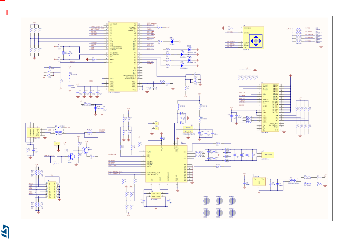
3.4 Electrical schematics
A detailed view of the electrical schemes for the EVAL-ST95HF board can be found in
Figure 6.
UM1761 Bill of material
DocID026283 Rev 2 11/19
4 Bill of material
The parts needed for the EVAL-ST95HF development kit are listed in Table 2.
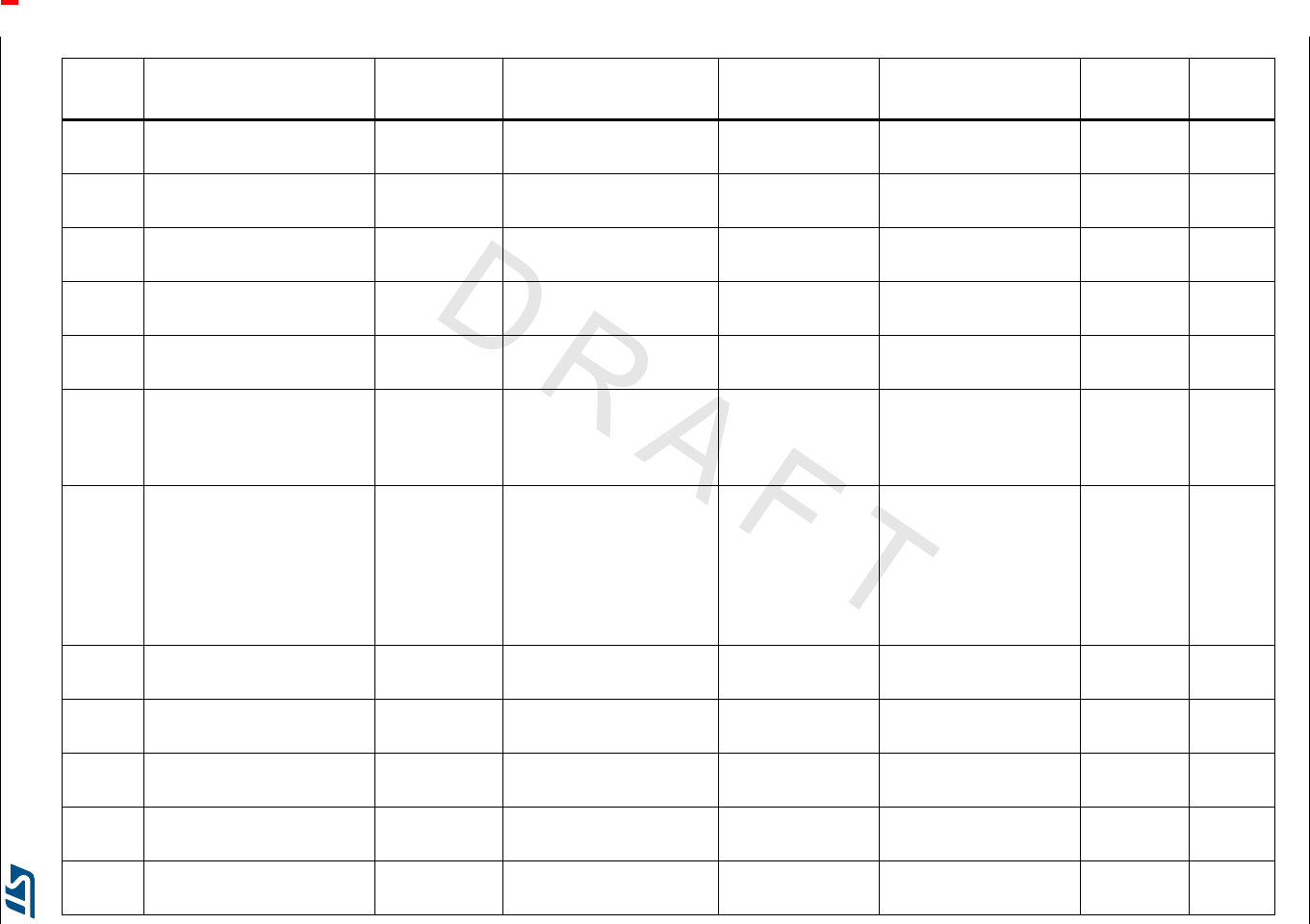
Table 2. Bill of materials
Quantity Description Reference Package Manufacturer Part number Distributor Order
code
1 ST95HFVMD5 ST95HF U1 VFQFPN32_5x5 STMicroelectronics ST95HF VMD5T - -
1MCU 32 BITS 1MB Flash
64LQFP STM32F103RGT6 U2 LQFP64_10x10 STMicroelectronics STM32F103RGT6 - -
13.3V Voltage regulator
KF33BDT U3 DPAK STMicroelectronics KF33BDT - -
1
Joystick
4 directions1 select
Wealth Metal Factory
MT008-A
U4 JOYSTICK_MT-008A Wealth Metal
Factory MT008-A - -
1 LCD Screen FRD24048 U5 SF-TC240T-48P-07 FRDA LCD FRD24048 - -
2
293D TANTAL SMD
POL CAP 1uF 16V 10%
Boitier A 1µF
C11, C17 293D-A - - Farnell 1754174
1
293D TANTAL SMD
POL CAP 2,2uF 35V 10%
Boitier C 2,2uF
C30 293D-C - - Farnell 1754228
1
293D TANTAL SMD
POL CAP 4,7uF 16V 10%
Boitier A 4.7µF
C33 293D-A - - Farnell 1754174
1
293D TANTAL SMD
POL CAP 10uF 35V 10%
boitier D 10uF
C19 293D-D - - Farnell 2112949
6CONDENSATEUR MLCC
0603 NP0 50V 2% NC(1)
C37, C38,
C40, C41, Cb,
Cc
0603 - - - -
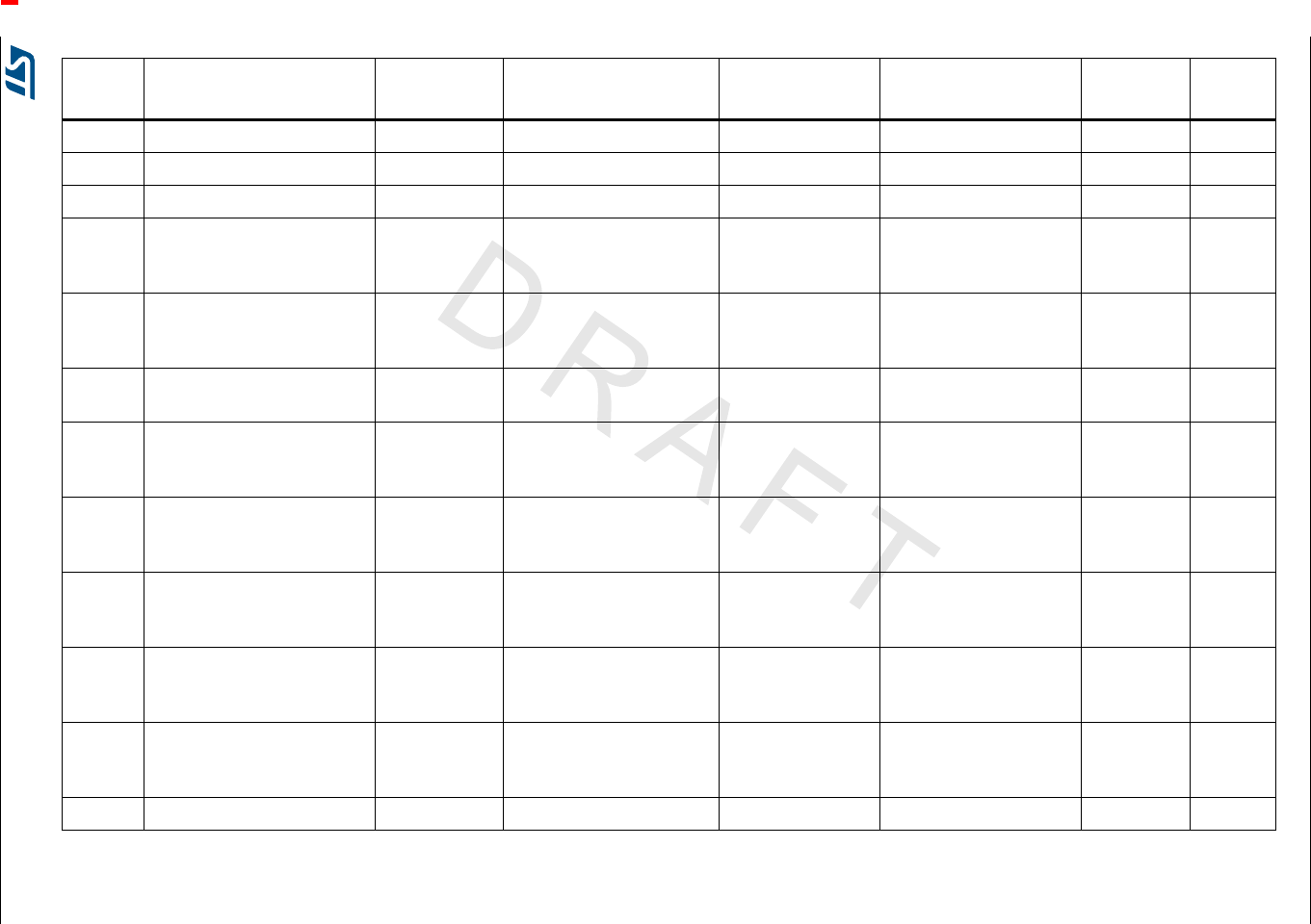
Bill of material UM1761
12/19 DocID026283 Rev 2
2CONDENSATEUR MLCC
0603 NP0 50V 2% 47pF C22, C25 0603 Murata(2) GRM1885C1H470GA01 - -
4CONDENSATEUR MLCC
0603 NP0 50V 2% 100pF
C23, C24,
C35, C36 0603 Murata(2) GRM1885C1H101GA01 - -
1CONDENSATEUR MLCC
0603 NP0 50V 2% 82pF Ca 0603 Murata(2) GRM1885C1H820GA01 - -
2CONDENSATEUR MLCC
0603 NP0 50V 5% 10pF C27, C28 0603 - - Farnell 1759053
2CONDENSATEUR MLCC
0603 NP0 50V 5% 20pF C1, C4 0603 - - Farnell 1844172
1CONDENSATEUR MLCC
0603 NP0 50V 5% 1nF C21 0603 - - Farnell 1759089
1CONDENSATEUR MLCC
0603 NP0 50V 5% 4,7nF C26 0603 - - Farnell 1833869
2CONDENSATEUR MLCC
0603 NP0 50V 5% 10nF C16, C18 0603 - - Farnell 1833871
18 CONDENSATEUR MLCC
0603 NP0 50V 5% 100nF
C2, C3, C5,
C6, C7, C8,
C9, C10, C12,
C13, C14,
C15, C20,
C29, C31,
C32, C34, C39
0603 - - Farnell 1740621
1
NOISE SUPPRESSOR
CMS 90OHM. 370MA
744232090
FL1 744232xxx WURTH
ELEKTRONIK(2) 744232090 Farnell 1636474
1
NOISE SUPPRESSOR
CMS 90OHM. 0.37A
DLW31SN900SQ2
FL2 744232xxx Murata(2) DLW31SN900SQ2 Radiospares 724-1687
Table 2. Bill of materials (continued)
Quantity Description Reference Package Manufacturer Part number Distributor Order
code
UM1761 Bill of material
DocID026283 Rev 2 13/19
1
FILTER SUPPRESSION,
0603, 1UF, 6.3VDC
NFM18PS105R0J3D
FL3 NFM18PS Murata(2) NFM18PS105R0J3D Farnell 1686506
5FERRITE CMS 600OHM.
0805 742792042
L1, L2, L3,
L8, L9 0805 WURTH
ELEKTRONIK(2) 742792042 Farnell 1635716
1FERRITE CMS 2200OHM.
0805 742792093 L10 0805 WURTH
ELEKTRONIK(2) 742792093 Farnell 1635726
1
FERRITE BEAD, 0.38OHM,
500MA, 0603
BLM18AG601SN1D
L4 0603 Murata(2) BLM18AG601SN1D Farnell 1515679
1FERRITE CMS 300OHM.
0603 742792641 L7 0603 WURTH
ELEKTRONIK(2) 742792641 Farnell 1635705
2Inductor SMD 0805,
LQM21NNR56K10D 560nH L5, L6 0805 Murata(2) LQM21NNR56K10D Radiospares 786-7087
12 Resistance CMS 0603 0,1W
5% NC(1)
R12, R16,
R29, R30,
R53, R56,
R58, R59,
R65, R67,
R69, Rq
0603 - - - -
16 Resistance CMS 0603 0,1W
5% 0
R13, R15,
R31, R32,
R37, R38,
R47, R61,
R62, R63,
R64, R66,
R68, R70,
R72, R73
0603 - - - -
3Resistance CMS 0603 0,1W
5% 10 R3, R20, R21 0603 - - - -
1Resistance CMS 0603 0,1W
5% 180 R46 0603 - - - -
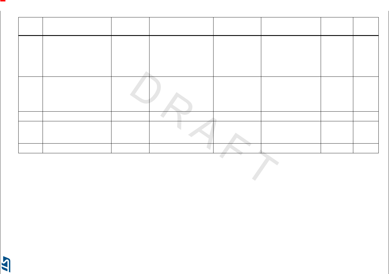
Table 2. Bill of materials (continued)
Quantity Description Reference Package Manufacturer Part number Distributor Order
code
Bill of material UM1761
14/19 DocID026283 Rev 2
2Resistance CMS 0603 0,1W
5% 330 Z-RX1, Z-RX2 0603 - - - -
1Resistance CMS 0603 0,1W
5% 560 R43 0603 - - - -
3Resistance CMS 0603 0,1W
5% 1k R2, R44, R45 0603 - - - -
1Resistance CMS 0603 0,1W
5% 1.5k R28 0603 - - - -
5Resistance CMS 0603 0,1W
5% 3.3k
R17, R18,
R19, R23, R24 0603 - - - -
10 Resistance CMS 0603 0,1W
5% 4.7k
R1, R48, R49,
R50, R51,
R52, R54,
R55, R57, R60
0603 - - - -
17 Resistance CMS 0603 0,1W
5% 10k
R5, R6, R7,
R8, R9, R10,
R11, R22,
R33, R34,
R35, R36,
R39, R40,
R41, R42, R71
0603 - - - -
1Resistance CMS 0603 0,1W
5% 36k R27 0603 - - - -
1Resistance CMS 0603 0,1W
5% 47k R25 0603 - - - -
2Resistance CMS 0603 0,1W
5% 1M R4, R26 0603 - - - -
1Mini USB
5075BMR-05-SM J2 5075BMR-05-SM Neltron Industrial 5075BMR-05-SM - -
1HEADER, RIGHT ANGLE,
20WAY J3 HE10_20PTS_M_COUDE MULTICOMP MC9A22-2034 Farnell 1099248
Table 2. Bill of materials (continued)
Quantity Description Reference Package Manufacturer Part number Distributor Order
code
UM1761 Bill of material
DocID026283 Rev 2 15/19
2 Connector 1PT, NC ST1, ST3 CON_1PTS FCI 77311-401-36LF Farnell 1097954
1 Connector 3PTS 2,54, NC(1) ST2 CON_3PTS_P2.54 FCI 77311-401-36LF Farnell 1097954
2 Push Button SW_BP_ST(1) SW1, SW2 FSM4JSMA ALCOSWITCH FSM4JSMA Farnell 3801305
1
LED, 1206, RED,
80MCD, 635NM
RED Led
LED1 LED-1206 DIALIGHT 598-8210107F Farnell 1850747
1
LED, 1206,YELLOW,
130MCD, 593NM YELLOW
Led
LED2 LED-1206 DIALIGHT 5988240107F Farnell 1465998
1LED, 1206, BLUE, 140MCD
BLUE Led LED3 LED-1206 DIALIGHT 5988291107F Farnell 1850752
1
LED, 1206, ORANGE,
110MCD, 610NM ORANGE
Led
LED4 LED-1206 DIALIGHT 5988230107F Farnell 1872396
1
LED, 1206, GREEN,
20MCD, 570NM
GREEN Led
LED5 LED-1206 DIALIGHT 5988270107F Farnell 1466000
2
BC817-16 - TRANSISTOR
NPN 0.5A 45V SOT23
BC817
Q1, Q2 SOT23 MULTICOMP BC817-16 Farnell 1798077
1
SMD CRYSTAL
OSCILLATOR,8M,20PF,20p
pm 8MHz
Y1 HC49SD FOX
ELECTRONICS(2) FOXSDLF/080-20 Farnell 2063972
1
NX2016SA 27.12MHz
EXS00A-CS01188
27.12MHz
Y2 NX2016 NDK(2) NX2016SA 27.12MHz
EXS00A-CS01188 --
1 NFC Antenna(1) ant1 ANT_90DEG - - - -
Table 2. Bill of materials (continued)
Quantity Description Reference Package Manufacturer Part number Distributor Order
code
Bill of material UM1761
16/19 DocID026283 Rev 2
6 PCB MIRE(1)
MIRE1,
MIRE2,
MIRE3,
MIRE4,
MIRE5,
MIRE6
MIRE - - - -
1
PCB(3)
150mmx60mmx1.6mm
(FR4, dual side,
components on both sides,
green color)
-- - ---
5 Bumpon protective product - 3M SJ5306 - - -
1
Five_way switch button hat,
PB-504/PB-MT008A (Cyan),
along, AKG004, for U4
-- - ---
1 Carton box(1) -- - ---
1. Not fitted
2. No double source allowed
3. Version B
Table 2. Bill of materials (continued)
Quantity Description Reference Package Manufacturer Part number Distributor Order
code

DocID026283 Rev 2 17/19
UM1761 Federal Communications Commission (FCC) and Industry Canada (IC) compliance state-
18
5 Federal Communications Commission (FCC) and
Industry Canada (IC) compliance statements
5.1 FCC Compliance Statement
5.1.1 Part 15.19
This device complies with Part 15 of the FCC Rules. Operation is subject to the following
two conditions: (1) this device may not cause harmful interference, and (2) this device must
accept any interference received, including interference that may cause undesired
operation.
5.1.2 Part 15.21
Any changes or modifications to this equipment not expressly approved by
STMicroelectronics may cause harmful interference and void the user’s authority to operate
this equipment.
5.1.3 FCC ID
FCC ID: YCPEVALST95HF
5.2 IC Compliance Statement
5.2.1 Compliance Statement
This device complies with Industry Canada licence-exempt RSS standard(s). Operation is
subject to the following two conditions: (1) this device may not cause interference, and (2)
this device must accept any interference, including interference that may cause undesired
operation.
5.2.2 Déclaration de conformité
Le présent appareil est conforme aux CNR d’Industrie Canada applicables aux appareils
radio exempts de licence. L’exploitation est autorisée aux deux conditions suivantes: (1)
l’appareil ne doit pas produire de brouillage, et (2) l’utilisateur de l’appareil doit accepter tout
brouillage radioélectrique subi, même si le brouillage est susceptible d’en compromettre le
fonctionnement.
5.2.3 IC ID
IC ID: 8976A-EVALST95HF

DocID026283 Rev 2 19/19
UM1761
19
IMPORTANT NOTICE – PLEASE READ CAREFULLY
STMicroelectronics NV and its subsidiaries (“ST”) reserve the right to make changes, corrections, enhancements, modifications, and
improvements to ST products and/or to this document at any time without notice. Purchasers should obtain the latest relevant information on
ST products before placing orders. ST products are sold pursuant to ST’s terms and conditions of sale in place at the time of order
acknowledgement.
Purchasers are solely responsible for the choice, selection, and use of ST products and ST assumes no liability for application assistance or
the design of Purchasers’ products.
No license, express or implied, to any intellectual property right is granted by ST herein.
Resale of ST products with provisions different from the information set forth herein shall void any warranty granted by ST for such product.
ST and the ST logo are trademarks of ST. All other product or service names are the property of their respective owners.
Information in this document supersedes and replaces information previously supplied in any prior versions of this document.
© 2015 STMicroelectronics – All rights reserved