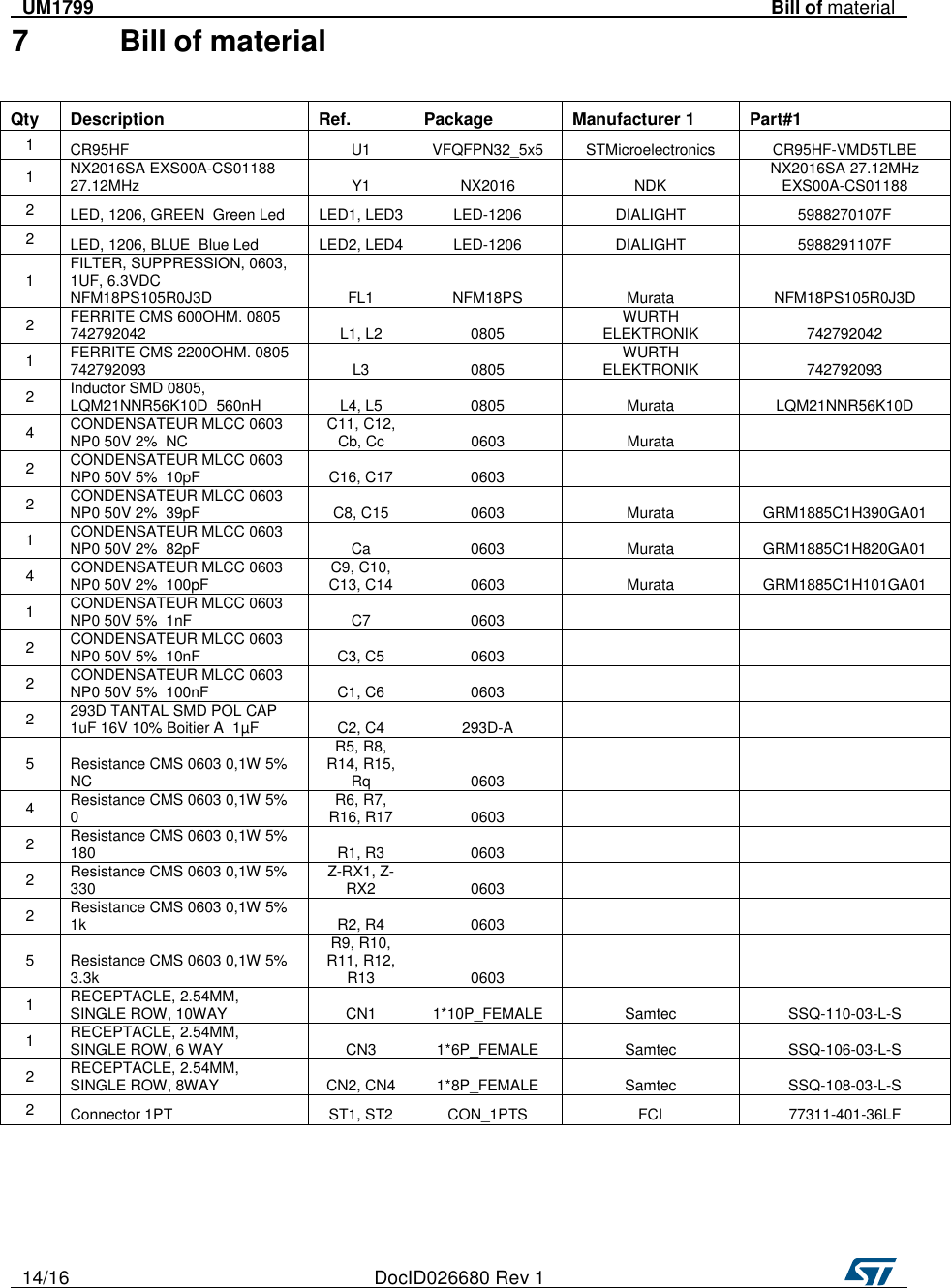
STMicroelectronicsS NFC03A1 NFC card reader board User Manual Users manual NFC03A1

STMicroelectronics NFC card reader board Users manual NFC03A1

User Manual

UM1799 User manual  Getting started with X-NUCLEO-NFC03A1 NFC card reader board based on CR95HF IC for STM32 Nucleo     Introduction The X-NUCLEO-NFC03A1 is an NFC card reader evaluation board based on CR95HF integrated circuit to allow expansion of the STM32 Nucleo boards. The CR95HF is card reader IC for contact-less application that provides the 13.56MHz air interface, frame coding and decoding for standard application such as Near Field Communication (NFC) and that communicates with the Host through UART or SPI interface. X-NUCLEO-NFC03A1 is compatible with the Arduino UNO R3 connector assignment.  This expansion board can be plugged into the Arduino UNO R3 connectors of any STM32 Nucleo board. The different expansion boards can be easily stacked to allow evaluation of different devices with NFC card reader.  The board has the following features:  • On-board NFC card reader IC: CR95HF • 47 x 34 mm, 4 turns, single layer 13.56 MHz inductive antenna etched on PCB and associated tuning circuit. • 4 general purpose LEDs   Figure 1: NFC card reader board based on CR95HF IC                                  March 2016  DocID026680 Rev 1  1/16    www.st.com
  2/16  DocID026680 Rev 1     Contents  UM1799   Contents 1  Getting started ................................................................................ 3 1.1  Hardware requirements .................................................................... 3 1.2  System requirements ....................................................................... 4 1.3  Setting up the board ......................................................................... 4 2  Hardware description ..................................................................... 5 2.1  X-NUCLEO-NFC03A1 board ............................................................ 5 2.2  Host interface and GPIO connection ................................................ 6 2.3  X-NUCLEO-NFC03A1 component placement .................................. 7 3  Component description.................................................................. 8 3.1  CR95HF integrated circuit ................................................................ 8 4  Formal notices required by the U.S. Federal Communications Commission ("FCC")  .............................................................................. 9 5  Formal notices required by the Industry Canada ("IC") ............. 10 6  Hardware schematic diagrams .................................................... 11 7  Bill of material ............................................................................... 13 8  Revision history ............................................................................ 15
   DocID026680 Rev 1  3/16      UM1799  Getting started     1 Getting started  This section describes the hardware requirements for the X-NUCLEO-NFC03A1 evaluation board.  1.1  Hardware requirements  The X-NUCLEO-NFC03A1 is an expansion board for use with STM32 Nucleo boards. To function correctly, the X-NUCLEO-IDB05A1 must be connected to the STM32 Nucleo board as shown in Figure 2: "X-NUCLEO-NFC03A1 plugged into an STM32 Nucleo board through the Arduino UNO R3 connector" below.  The STM32 Nucleo firmware and related documentation is available at http://www.st.com/stm32nucleo      Figure 2: X-NUCLEO-NFC03A1 plugged into an STM32 Nucleo board through the Arduino UNO R3 connector
  4/16  DocID026680 Rev 1          The interconnection between the STM32 Nucleo and the X-NUCLEO-NFC03A1 has been designed to permit the use of any STM32 Nucleo board, although complete testing has been performed using the NUCLEO-F401RE hosting the dynamic efficiency STM32.  1.2  System requirements  Using the Nucleo boards with the X-NUCLEO-NFC03A1 expansion board requires the following software and hardware:  • Windows PC (XP, Vista, 7, 8) to install the firmware package • USB type A to Mini-B USB cable to connect the Nucleo board to the PC   Installation of the board firmware package (order code: X-CUBE-NFC3) on the user's PC requires the following: • 128 MB of RAM • 40 MB of hard disk space  The X-CUBE-NFC3 firmware and related documentation is available on www.st.com  1.3  Setting up the board  To set up the board, perform the following steps:   1. Connect the X-NUCLEO-NFC03A1 on the Nucleo board from the top as shown in Figure 2: "X-NUCLEO-IDB05A1 plugged into an STM32 Nucleo board through the Arduino UNO R3 connector" 2. Power the Nucleo board using the Mini-B USB cable delivered with the board. 3. Program the firmware in the STM32 on the Nucleo board using the provided firmware example  4. Reset the MCU board using the reset button available on the Nucleo board 5. The evaluation kit is ready to be used
   DocID026680 Rev 1  5/16    expansion board   UM1799  Hardware description   2 Hardware description  This section describes the X-NUCLEO-NFC3A1 features and provides information which could be useful to understand the board schematic diagrams.  2.1  X-NUCLEO-NFC03A1 board  The board allows the user to test the functionality of the CR95HF integrated circuit. The CR95HF supports reader/writer mode and supports following communication protocols: ISO/IEC 14443 Type A and B, ISO/IEC 15693, ISO IEC18092, MIFARE ® Classic.  Its functionality can be exploited using the firmware package contained in the X-CUBE- NFC3. It is fundamental to program the microcontroller on the STM32 Nucleo board. Please refer to user manuals UM1724 and UM1725, available on www.st.com.  The CR95HF integrated circuit module and the STM32 Nucleo board are connected through connectors CN5, CN6, CN8 and CN9 (see Table 1: "Interconnection between STM32 Nucleo board and X-NUCLEO-NFC03A1 left-side connectors" for details).    Table 1: Interconnection between STM32 Nucleo board and X-NUCLEO-NFC03A1 left-side connectors    Signal Name  NC  IOREF  RESET  3V3  5V  GND  GND  VIN   A0  A1  A2  A3  A4  A5  Left connector   Connector   Name   CN6 Power    CN8 Analog    Pin#  1  2  3  4  5  6  7  8   1  2  3  4  5  6   NUCLEO-L053R8 (MCU Port)           PA0  PA1  PA4  PB0  PC1/ PB9  PC0/ PB8   X-NUCLEO-NFC03A1  3V3   3V3   GND  GND
  6/16  DocID026680 Rev 1     Hardware description  UM1799   Table 2: Interconnection between STM32 Nucleo board and X-NUCLEO- NFC03A1 right-side connectors   Signal Name  D15  D14  AREF  GND  D13  D12  D11  D10  D9  D8   D7  D6  D5  D4  D3  D2  D1  D0   Right connector  Connector Name   CN5 Digital    CN9 Digital  Pin#  10  9  8  7  6  5  4  3  2  1   8  7  6  5  4  3  2  1  NUCLEO-L053R8 (MCU Port)  PB8  PB9    PA5  PA6  PA7  PB6  PC7  PA9   PA8  PB10  PB4  PB5  PB3  PA10  PA2  PA3  X-NUCLEO-NFC03A1 expansion board     GND  SPI_CLK   SPI_MISO  SPI_MOSI  SPI_CS_NFC  Interface_Pin  UART_TX/IRQ_IN      MCU_LED1 MCU_LED2 MCU_LED2 MCU_LED2   UART_RX/IRQ_OUT        2.2  Host interface and GPIO connection   The X-NUCLEO-NFC03A1 board contains the CR95HF-VMD5T chip and is powered by STM32 Nucleo Board. Chip is driven by the microcontroller either via the SPI link or the UART link, selection is ensured by microcontroller at CR95HF reset. Four LEDS connected to microcontroller GPIOs are general purpose.
   DocID026680 Rev 1  7/16      UM1799  Hardware description      2.3  X-NUCLEO-NFC03A1 component placement  The following diagram shows the component placement on the X-NUCLEO-NFC03A1 board.  Figure 3: X-NUCLEO-NFC03A1 component placement details General Purpose LEDs CR95HF-VMD5T chip Matching circuitry 47*34 mm 4 turns antenna
  8/16  DocID026680 Rev 1     Component description  UM1799   3 Component description  The board has the following devices.  3.1  CR95HF integrated circuit  The CR95HF-VMD5T is an integrated transceiver IC for contactless application. It is manages frame coding and decoding in Reader mode for application such as near field communication (NFC) proximity and vicinity standards and embeds an analog front end to provide the 13.56MHz air interface and supports ISO/IEC 14443 Type A and Type B, ISO/IEC 15693 (single or double subcarrier) and ISO/IEC 18092 communication protocols.   The part numbers used to develop this application are shown in Table 4: "SPBTLE-RF details".  Table 4: CR95HF details  Feature Description Sales type  CR95HF-VMD5T Package  32-lead, 5*5 VFQFPN Operating voltage                               2.7 to 5.5V
   DocID026680 Rev 1  9/16     UM1799  Formal notices required by the U.S. Federal    Communications Commission ("FCC")   4 Formal notices required by the U.S. Federal Communications Commission ("FCC")  4.1. FCC Compliance Statement   4.1.1.  Part 15.19  This device complies with Part 15 of the FCC Rules. Operation is subject to the following two conditions: (1) this device may not cause harmful interference, and (2) this device must accept any interference received, including interference that may cause undesired operation.  4.1.2.  Part 15.19  Any changes or modifications to this equipment not expressly approved by STMicroelectronics may cause harmful interference and void the user’s authority to operate this equipment.  4.1.3.  Part 15.19  FCC ID: YCPNFC03A1
  10/16  DocID026680 Rev 1   Formal notices required by the Industry Canada UM1799   ("IC")    5 Formal notices required by the Industry Canada ("IC")  5.1. Compliance Statement    This device complies with Industry Canada licence-exempt RSS standard(s). Operation is subject to the following two conditions: (1) this device may not cause interference, and (2) this device must accept any interference, including interference that may cause undesired operation.   5.2. Declaration de Conformité    Le présent appareil est conforme aux CNR d’Industrie Canada applicables aux appareils radio exempts de licence. L’exploitation est autorisée aux deux conditions suivantes : (1) l’appareil ne doit pas produire de brouillage, et (2) l’utilisateur de l’appareil doit accepter tout brouillage radioélectrique subi, même si le brouillage est susceptible d’en compromettre le fonctionnement.  5.3. IC ID    Le présent appareil est conforme aux CNR d’Industrie Canada applicables aux appareils radio exempts de licence. L’exploitation est autorisée aux deux conditions suivantes : (1) l’appareil ne doit pas produire de brouillage, et (2) l’utilisateur de l’appareil doit accepter tout brouillage radioélectrique subi, même si le brouillage est susceptible d’en compromettre le fonctionnement.  IC ID: 8976A-NFC03A1
DocID026680 Rev 1 13/16    UM1799  Hardware schematic diagrams   6 Hardware schematic diagrams  Figure 4: Nucleo connectors
12/16 DocID028033 Rev 1     Figure 5: CR95HF
DocID026680 Rev 1 13/16    Hardware schematic diagrams  UM1799   Figure 6: General Purpose LEDs
  14/16  DocID026680 Rev 1     UM1799  Bill of material   7 Bill of material     Qty  Description  Ref.  Package  Manufacturer 1  Part#1 1  CR95HF  U1  VFQFPN32_5x5  STMicroelectronics  CR95HF-VMD5TLBE 1  NX2016SA EXS00A-CS01188  27.12MHz  Y1  NX2016  NDK  NX2016SA 27.12MHz EXS00A-CS01188 2  LED, 1206, GREEN  Green Led  LED1, LED3  LED-1206  DIALIGHT  5988270107F 2  LED, 1206, BLUE  Blue Led  LED2, LED4  LED-1206  DIALIGHT  5988291107F 1  FILTER, SUPPRESSION, 0603, 1UF, 6.3VDC  NFM18PS105R0J3D  FL1  NFM18PS  Murata  NFM18PS105R0J3D 2  FERRITE CMS 600OHM. 0805  742792042  L1, L2  0805  WURTH ELEKTRONIK  742792042 1  FERRITE CMS 2200OHM. 0805  742792093  L3  0805  WURTH ELEKTRONIK  742792093 2  Inductor SMD 0805, LQM21NNR56K10D  560nH  L4, L5  0805  Murata  LQM21NNR56K10D 4  CONDENSATEUR MLCC 0603 NP0 50V 2%  NC  C11, C12, Cb, Cc  0603  Murata   2  CONDENSATEUR MLCC 0603 NP0 50V 5%  10pF  C16, C17  0603     2  CONDENSATEUR MLCC 0603 NP0 50V 2%  39pF  C8, C15  0603  Murata  GRM1885C1H390GA01 1  CONDENSATEUR MLCC 0603 NP0 50V 2%  82pF  Ca  0603  Murata  GRM1885C1H820GA01 4  CONDENSATEUR MLCC 0603 NP0 50V 2%  100pF  C9, C10, C13, C14  0603  Murata  GRM1885C1H101GA01 1  CONDENSATEUR MLCC 0603 NP0 50V 5%  1nF  C7  0603     2  CONDENSATEUR MLCC 0603 NP0 50V 5%  10nF  C3, C5  0603     2  CONDENSATEUR MLCC 0603 NP0 50V 5%  100nF  C1, C6  0603     2  293D TANTAL SMD POL CAP 1uF 16V 10% Boitier A  1µF  C2, C4  293D-A     5  Resistance CMS 0603 0,1W 5%  NC R5, R8, R14, R15, Rq  0603     4  Resistance CMS 0603 0,1W 5%  0  R6, R7, R16, R17  0603     2  Resistance CMS 0603 0,1W 5%  180  R1, R3  0603     2  Resistance CMS 0603 0,1W 5%  330  Z-RX1, Z-RX2  0603     2  Resistance CMS 0603 0,1W 5%  1k  R2, R4  0603     5  Resistance CMS 0603 0,1W 5%  3.3k R9, R10, R11, R12, R13  0603     1  RECEPTACLE, 2.54MM, SINGLE ROW, 10WAY    CN1  1*10P_FEMALE  Samtec  SSQ-110-03-L-S 1  RECEPTACLE, 2.54MM, SINGLE ROW, 6 WAY    CN3  1*6P_FEMALE  Samtec  SSQ-106-03-L-S 2  RECEPTACLE, 2.54MM, SINGLE ROW, 8WAY    CN2, CN4  1*8P_FEMALE  Samtec  SSQ-108-03-L-S 2  Connector 1PT    ST1, ST2  CON_1PTS  FCI  77311-401-36LF
   DocID026680 Rev 1  15/16      UM1799  Revision history   8 Revision history  Table 8: Document revision history  Date Revision Changes 03-Apr-2016  1  First draft
  16/16  DocID026680 Rev 1      UM1799        IMPORTANT NOTICE – PLEASE READ CAREFULLY   STMicroelectronics NV and its subsidiaries (“ST”) reserve the right to make changes, corrections, enhancements, modifications, and improvements to ST products and/or to this document at any time without notice. Purchasers should obtain the latest relevant information on ST products before placing orders. ST products are sold pursuant to ST’s terms and conditions of sale in place at the time of order acknowledgement.   Purchasers are solely responsible for the choice, selection, and use of ST products and ST assumes no liability for application assistance or the design of Purchasers’ products.   No license, express or implied, to any intellectual property right is granted by ST herein.   Resale of ST products with provisions different from the information set forth herein shall void any warranty granted by ST for such product.   ST and the ST logo are trademarks of ST. All other product or service names are the property of their respective owners.   Information in this document supersedes and replaces information previously supplied in any prior versions of this document.   © 2015 STMicroelectronics – All rights reserved

Navigation menu