STMicroelectronicsS STM32WLCDL RF Control Kit User Manual
STMicroelectronics RF Control Kit Users Manual
Users Manual

February 2011 Doc ID 18433 Rev 1 1/8
UM1050
User manual
STM32W-RFCKIT
Low-cost RF control kit for STM32W108xx microcontrollers
1 Introduction
The STM32W-RFCKIT low-cost RF control kit is an easy-to-use tool for STM32W108xx RF
microcontrollers. This family of microcontrollers integrates a 32-bit ARM® Cortex™-M3
microprocessor and a 2.4 GHz, IEEE 802.15.4-compliant transceiver. The kit demonstrates
plug and play 2.4GHz RF point-to-point communications targeting general-purpose wireless
control systems.
The STM32W-RFCKIT RF control kit provides demonstration applications and
documentation which serve as a reference for creating your own applications and re-
programming the STM32W108xx microcontroller.
You can run the STM32W-RFCKIT RF control kit in several ways using the dedicated
software libraries (Simplified MAC, ZigBee RF4CE and ZigBee PRO). This kit provides
access to a set of straightforward HAL APIs enabling application engineers to easily develop
RF control capabilities such as LEDs, serial communication channels (virtual COM through
USB), MEM enabled pointers, etc. Moreover, thanks to the flexibility of STM32W
microcontrollers, developers will also be able to use the kit with other available protocol
network libraries: MAC based, RF4CE, ZigBee PRO or 6LowPan.
This manual provides information about:
■STM32W-RFCKIT RF control kit components
■How to install the related hardware, software and documentation trees
■How to run the preprogrammed demonstration applications
Note: For more information, visit the STM32W 32-bit RF microcontroller webpages at
www.st.com/stm32w_rfcontrol
These webpages provide full access to all STM32W108xx resources (kits, software
packages and documents).
www.st.com

Contents UM1050
2/8 Doc ID 18433 Rev 1
Contents
1 Introduction . . . . . . . . . . . . . . . . . . . . . . . . . . . . . . . . . . . . . . . . . . . . . . . . 1
2 Getting started . . . . . . . . . . . . . . . . . . . . . . . . . . . . . . . . . . . . . . . . . . . . . . 3
2.1 Kit description . . . . . . . . . . . . . . . . . . . . . . . . . . . . . . . . . . . . . . . . . . . . . . . 3
2.1.1 Hardware . . . . . . . . . . . . . . . . . . . . . . . . . . . . . . . . . . . . . . . . . . . . . . . . . 3
2.1.2 Software . . . . . . . . . . . . . . . . . . . . . . . . . . . . . . . . . . . . . . . . . . . . . . . . . . 3
2.1.3 Documentation . . . . . . . . . . . . . . . . . . . . . . . . . . . . . . . . . . . . . . . . . . . . . 3
2.2 Software libraries and demonstration applications . . . . . . . . . . . . . . . . . . . 4
2.3 Kit setup . . . . . . . . . . . . . . . . . . . . . . . . . . . . . . . . . . . . . . . . . . . . . . . . . . . 4
2.3.1 Powering on the boards . . . . . . . . . . . . . . . . . . . . . . . . . . . . . . . . . . . . . . 4
2.3.2 Installing the ST Virtual COM port driver USB drive . . . . . . . . . . . . . . . . 4
2.3.3 Setting up the application serial communication channel . . . . . . . . . . . . 4
3 Running the STM32W-RFCKIT RF control kit . . . . . . . . . . . . . . . . . . . . . 5
3.1 Installing the STM32W-RFCKIT RF control kit software tree . . . . . . . . . . . 5
3.1.1 Building and download the Simple MAC talk demonstration application . 5
3.1.2 Basic RF communication using the talk demonstration application . . . . . 6
4 STM32W-RFCKIT utilities and software tools . . . . . . . . . . . . . . . . . . . . . 7
4.1 stm32w_flasher utility . . . . . . . . . . . . . . . . . . . . . . . . . . . . . . . . . . . . . . . . . 7
5 List of acronyms . . . . . . . . . . . . . . . . . . . . . . . . . . . . . . . . . . . . . . . . . . . . 7
6 Revision history . . . . . . . . . . . . . . . . . . . . . . . . . . . . . . . . . . . . . . . . . . . . 7
UM1050 Getting started
Doc ID 18433 Rev 1 3/8
2 Getting started
This section provides a complete description of the STM32W-RFCKIT RF control kit's
hardware and software.
2.1 Kit description
2.1.1 Hardware
The STM32W-RFCKIT RF control kit's package contains the following hardware
components:
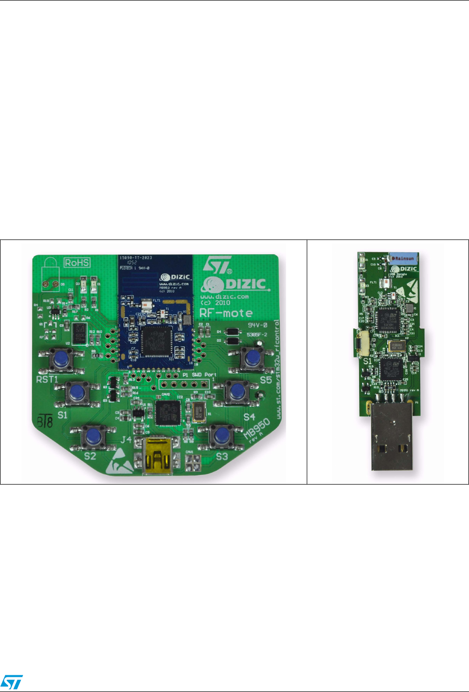
●One STM32W108xx MB950 remote application board
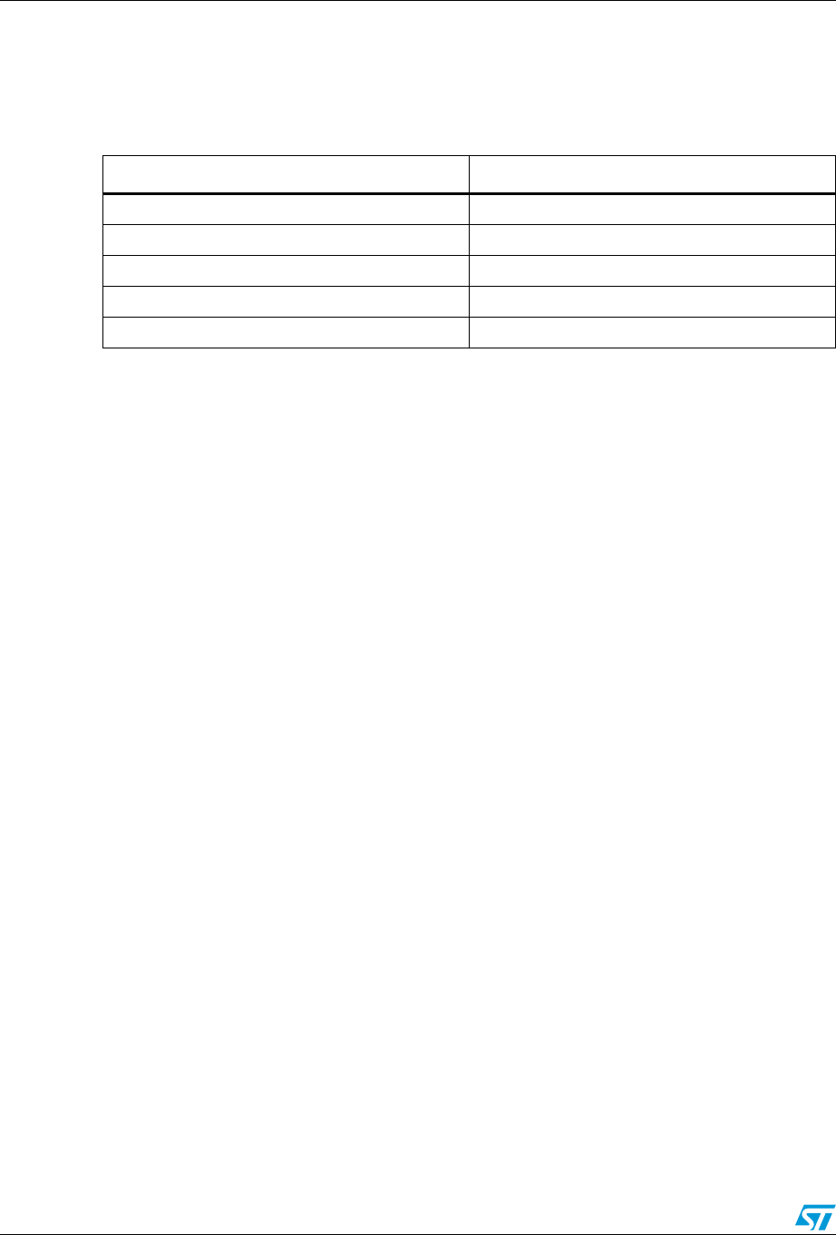
●One STM32W108xx MB951 USB dongle
Note: For information concerning the STM32W108xx MB950 and MB951 boards, refer to the
documentation included with all available software and the documentation tree installer file
(see Section 2.2: Software libraries and demonstration applications).
2.1.2 Software
The STM32W-RFCKIT RF control kit does not contain any CD-ROMs.
2.1.3 Documentation
The STM32W-RFCKIT RF control kit contains a welcome letter which briefly describes its
components and targeted applications.
Figure 1. MB950 remote application board Figure 2. MB951 USB dongle

Getting started UM1050
4/8 Doc ID 18433 Rev 1
2.2 Software libraries and demonstration applications
The following installer files are available on the STM32W 32-bit RF microcontroller
webpages:
●ST Simple MAC-1.0.2.0-STM32W108: installer file which provides the STM32W108
Simple MAC software library and demonstration applications targeting point-to-point
communication scenarios based on the IEEE 802.15.4 protocol.
●ST ZigBee RF4CE-1.2.0.0-STM32W108: installer file which provides the STM32W108
ZigBee RF4CE software library and demonstration applications for controlling an
RF4CE-compliant TV using an RF4CE-compliant remote control.
●EmberZNet-4.3.0.0-STM32W108: installer file which provides the EmberZNet™ 4.3.0
GA software libraries and demonstration applications targeting the mesh network
scenarios based on the ZigBee PRO protocol stack.
Note: 1 For a detailed description of software and documentation trees, refer to the related
documentation (starting from the HTML index file, that comes with each installer file).
2 Each installer file also provides a set of prebuilt binary images (applications and utilities).
3 For the most recent installer file versions, visit the STM32W 32-bit RF microcontroller
webpages at www.st.com/stm32w_rfcontrol
2.3 Kit setup
2.3.1 Powering on the boards
The MB950 application board can be powered as follows:
●Via batteries
●Via USB
To power on the MB951 USB dongle, simply plug it into a PC USB port.
2.3.2 Installing the ST Virtual COM port driver USB drive
To use the serial communication channel on the kit application boards, a Virtual COM port
driver for STM32F103xx must be installed. This driver can be directly downloaded from the
ST website at http://www.st.com/internet/com/SOFTWARE_RESOURCES/
SW_COMPONENT/SW_DRIVER/vcpdriver_v1.zip
2.3.3 Setting up the application serial communication channel
To setup a serial communication channel for the kit application boards, follow these steps:
1. On the MB950 application board, connect a mini-USB cable between the board’s mini-
USB connector and a PC USB port.
2. Plug the MB951 USB dongle into a PC USB port.
3. Using the mouse, right-click on My Computer, select Manage, Device Manager, and
open Ports (COM & LPT) to display the related USB COMx ports.
4. Open a Hyper Terminal on the corresponding USB virtual COMx ports with the
following configuration:
Bit rate: 115200; Data bits: 8; Parity: None; Stop bits: 1; Flow control: None

UM1050 Running the STM32W-RFCKIT RF control kit
Doc ID 18433 Rev 1 5/8
3 Running the STM32W-RFCKIT RF control kit
In the STM32W-RFCKIT RF control kit, the Simple MAC talk application is preprogrammed
on both kit boards.
The Simple MAC talk demonstration application is a simple application that demonstrates
point-to-point IEEE 802.15.4 wireless communications using the STM32W108xx MCU.
It allows basic RF control of the USB dongle LEDs by pushing the application board's
buttons. Further, it can be used as a wireless RS-232 cable replacement. For example, all
data received on the serial port will be sent wirelessly to the other board and all the data
received wirelessly will be sent to the serial port.
3.1 Installing the STM32W-RFCKIT RF control kit software tree
To install the specific kit software and documentation tree, download the related installer file
from the STM32W 32-bit RF microcontroller webpages, then start the installation process
on your destination folder.
3.1.1 Building and download the Simple MAC talk demonstration application
The Simple MAC talk demonstration application runs on all STM32W-RFCKIT RF control kit
boards.
Using the prebuilt talk binary image
To download and run the prebuilt talk binary image on the kit's board, use the
stm32w_flasher utility with the prebuilt talk.s37 binary file. For information on how to use the
stm32w_flasher utility, refer to Section 4.1: stm32w_flasher utility.
Using the talk IAR project
An IAR workspace is also provided for building the Simple MAC talk demonstration
application.
Follow these steps to build the talk demonstration application image talk.s37.
1. Open the IAR toolset.
2. From the File, Open, Workspace menu, open the talk.eww IAR project.
3. From the Project menu, select Rebuild All. A binary file talk.s37 is built in the specific
demonstration application directory under the selected installation path.
Note: For the talk application, two workspaces are provided:
1. STM32W108 used to build a binary image with no IAP bootloader support.
2. STM32W108-btl used to build a binary image supporting the IAP bootloader (file
iap_bootloader.s37 in the prebuilt folder).
Running the STM32W-RFCKIT RF control kit UM1050
6/8 Doc ID 18433 Rev 1
3.1.2 Basic RF communication using the talk demonstration application
Once the talk application has been loaded on the kit's board, different RF communication
scenarios can be targeted as described in the table below.
Note: 1 When pressing a button on the application board, LED D1 is turned on, indicating a packet
is going to be sent.
2 When pressing a button on the application board, if something is wrong with the current RF
communication (packet transmission failed or no acknowledgment received from the USB
dongle), the application board LEDs D1 and D3 start blinking for few seconds.
For setting a “chat communication”, it is requested to setup a serial communication channel
on both kit's boards by following the steps described in Section 2.3.3: Setting up the
application serial communication channel.
Once the serial communication channels of the kit's boards are correctly configured, the two
talk demonstration applications can communicate by typing the “chat text” on the
corresponding HyperTerminal.
The above example application shows how an RS-232 cable connection between two
devices can be replaced with a wireless system using STM32W108xx microcontrollers.
Table 1. Supported talk RF control scenarios through application board buttons
Application board USB dongle
Press button S1 LED D1 toggles
Press button S2 LED D3 toggles
Press button S3 LED D1, D3 both toggle
Press button S4 LED D1 blinks for few seconds
Press button S5 LED D3 blinks for few seconds
UM1050 STM32W-RFCKIT utilities and software tools
Doc ID 18433 Rev 1 7/8
4 STM32W-RFCKIT utilities and software tools
4.1 stm32w_flasher utility
The stm32w_flasher utility allows you to download a binary file into the STM32W-RFCKIT
RF control kit's boards. This utility comes with the Simple MAC software installer file.
To download a binary image, follow these steps:
1. Connect the kit board to a PC USB port.
2. Using the mouse, right-click on My Computer, select Manage, Device Manager, and
open Ports (COM & LPT) to display the related USB COMx port.
3. Open a DOS Window on your PC and go to the utilities folder which is created after the
installation process.
4. Type the following command:
stm32w_flasher -p <COMx> -r -f <file_name.bin/.s37>
where COMx is the virtual COM related to the connected application board, and
file_name.bin/.s37 is the application image to be downloaded.
5 List of acronyms
6 Revision history
Table 2. List of acronyms
Term Meaning
API Application programming interfaces
CERC Consumer electronic remote control
GA General availability
HAL Hardware abstraction layer
IDE Integrated development tool
MAC Media access control
RC Remote control
RF Radio frequency communication
USB Universal serial bus
Table 3. Document revision history
Date Revision Changes
14-Feb-2011 1 Initial release.

UM1050
8/8 Doc ID 18433 Rev 1
Please Read Carefully:
Information in this document is provided solely in connection with ST products. STMicroelectronics NV and its subsidiaries (“ST”) reserve the
right to make changes, corrections, modifications or improvements, to this document, and the products and services described herein at any
time, without notice.
All ST products are sold pursuant to ST’s terms and conditions of sale.
Purchasers are solely responsible for the choice, selection and use of the ST products and services described herein, and ST assumes no
liability whatsoever relating to the choice, selection or use of the ST products and services described herein.
No license, express or implied, by estoppel or otherwise, to any intellectual property rights is granted under this document. If any part of this
document refers to any third party products or services it shall not be deemed a license grant by ST for the use of such third party products
or services, or any intellectual property contained therein or considered as a warranty covering the use in any manner whatsoever of such
third party products or services or any intellectual property contained therein.
UNLESS OTHERWISE SET FORTH IN ST’S TERMS AND CONDITIONS OF SALE ST DISCLAIMS ANY EXPRESS OR IMPLIED
WARRANTY WITH RESPECT TO THE USE AND/OR SALE OF ST PRODUCTS INCLUDING WITHOUT LIMITATION IMPLIED
WARRANTIES OF MERCHANTABILITY, FITNESS FOR A PARTICULAR PURPOSE (AND THEIR EQUIVALENTS UNDER THE LAWS
OF ANY JURISDICTION), OR INFRINGEMENT OF ANY PATENT, COPYRIGHT OR OTHER INTELLECTUAL PROPERTY RIGHT.
UNLESS EXPRESSLY APPROVED IN WRITING BY AN AUTHORIZED ST REPRESENTATIVE, ST PRODUCTS ARE NOT
RECOMMENDED, AUTHORIZED OR WARRANTED FOR USE IN MILITARY, AIR CRAFT, SPACE, LIFE SAVING, OR LIFE SUSTAINING
APPLICATIONS, NOR IN PRODUCTS OR SYSTEMS WHERE FAILURE OR MALFUNCTION MAY RESULT IN PERSONAL INJURY,
DEATH, OR SEVERE PROPERTY OR ENVIRONMENTAL DAMAGE. ST PRODUCTS WHICH ARE NOT SPECIFIED AS "AUTOMOTIVE
GRADE" MAY ONLY BE USED IN AUTOMOTIVE APPLICATIONS AT USER’S OWN RISK.
Resale of ST products with provisions different from the statements and/or technical features set forth in this document shall immediately void
any warranty granted by ST for the ST product or service described herein and shall not create or extend in any manner whatsoever, any
liability of ST.
ST and the ST logo are trademarks or registered trademarks of ST in various countries.
Information in this document supersedes and replaces all information previously supplied.
The ST logo is a registered trademark of STMicroelectronics. All other names are the property of their respective owners.
© 2011 STMicroelectronics - All rights reserved
STMicroelectronics group of companies
Australia - Belgium - Brazil - Canada - China - Czech Republic - Finland - France - Germany - Hong Kong - India - Israel - Italy - Japan -
Malaysia - Malta - Morocco - Philippines - Singapore - Spain - Sweden - Switzerland - United Kingdom - United States of America
www.st.com
This equipment complies with FCC and IC radiation exposure limits set forth for an uncontrolled environment. End users must follow the specific
operating instructions for satisfying RF exposure compliance.
This transmitter must not be co-located or operating in conjunction with any other antenna or transmitter.
The RF Control Kit must be installed and operated at a distance no closer then 8 inches (20 cm) from the user.
FCC: 15.21 “Changes or modifications are not expressly approved by the manufacturer could void the user's authority to operate the equipment.”
This device complies with part 15 of the FCC Rules. Operation is subject to the following two conditions: (1)This device may not cause harmful
interference, and (2) this device must accept any interference received,including interference that may cause undesired operation
This equipment has been tested and found to comply with the limits for a Class B digital device, pursuant to Part 15 of the FCC Rules. These limits are
designed to provide reasonable protection against harmful interference in a residential installation. This equipment generates, uses and can radiate
radio frequency energy and, if not installed and used in accordance with the instructions, may cause harmful interference to radio communications.
However, there is no guarantee that interference will not occur in a particular installation. If this equipment does cause harmful interference to radio or
television reception,which can be determined by turning the equipment off and on, the user is encouraged to try to correct the interference by one or
more of the following measures:
-- Reorient or relocate the receiving antenna.
-- Increase the separation between the equipment and receiver.
-- Connect the equipment into an outlet on a circuit different from that to which the receiver is connected.
-- Consult the dealer or an experienced radio/TV technician for help.
IC: "Operation is subject to the following two conditions: (1) this device may not cause interference, and (2) this device must accept any interference,
including interference that may cause undesired operation of the device."