SUNCAST Building Manual L0907179
User Manual: SUNCAST SUNCAST Building Manual SUNCAST Building Owner's Manual, SUNCAST Building installation guides
Open the PDF directly: View PDF ![]() .
.
Page Count: 32
OWNER'S MANUAL 7 1/2' x 3' Mini Storage Building
• Consult your local authorities for any permits required to construct shed.
Prior to the construction of your shed, check with the local building code official to review any required
permits or building limitations.
•A level and sturdy foundation is required before shed construction can begin.
Foundation recommendations and options are available in this manual.
•Read instructions thoroughly prior to assembly.
This kit contains parts that can be damaged if assembled incorrectly or in the wrong sequence.
•Please follow instructions.
Suncast is not responsible for replacing parts lost or damaged due to incorrect assembly.
•Check for all parts before you begin.
Using the provided parts check list on page 3, verify that you have all the parts required to construct your
shed model. COMPLETE SITE PREPARATION AND FOUNDATION CONSTRUCTION BEFORE
UNPACKING ALL PARTS.
•Assistance is required.
Due to the size of the parts, at least two people are required to handle, fit and secure shed components.
• Shed not intended for use in extreme weather conditions.
• Shed not intended for storage of flammable or caustic chemicals.
• Store heavy items near the bottom of shed.
• Shed not intended for use by children.
• Do not stand, sit, or store items on storage shed roof.
• Treat carefully in extreme temperatures.
• Repair or replace broken parts immediately.
• Suncast is not responsible for damage caused by weather or misuse.
• At regular intervals inspect your shed to make sure that assembly integrity has been maintained.
• Periodically check that the location you have chosen to set your shed is still level.
° This kit contains parts with metal edges. Please be careful when handling.
© 2007 Suncast Corporation, Batavia, IL 10361003A
• Wash shed with garden hose or mild detergent solution and soft cloth. Do not use a stiff brush or abrasive cleaner
as that could damage shed.
• Hot items, such as recently used grills, blowtorches, etc., must not be stored in the shed.
• Heavy articles should not be leaned against the walls, as this may cause panel distortion and permanent damage.
• Keep roof clean of snow and leaves.
• Flat blade screwdriver
• Phillips head screwdriver
• Small rubber mallet
• Adjustable wrench
• Ladder
• Eye protection
• Level
• Light duty work gloves
•Complete site preparation and foundation construction before unpacking
parts and beginning assembly.
•Do not attempt to assemble on a day with strong winds.
•Do not attempt to assemble on days when temperature is below 32 degrees.
• Set aside appropriate amount of time to completely assemble shed.
•Make sure you have assistance nearby to lift and secure parts in place.
•Wear light duty work gloves while assembling shed.
•If you have questions on assembly, please call 800-846-2345.
NOTE: This product contains parts that are used in different orientations to construct the shed.
Please take note of the orientation of the parts shown throughout this instruction manual. Failure to
follow instructions could result in damage to parts. Suncast is not responsible for replacing parts lost
or damaged due to incorrect assembly.
2
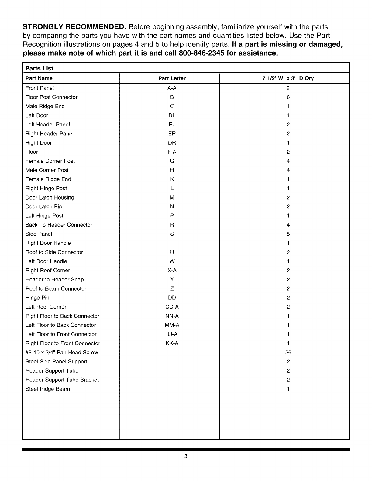
STRONGLY RECOMMENDED: Before beginning assembly, familiarize yourself with the parts
by comparing the parts you have with the part names and quantities listed below. Use the Part
Recognition illustrations on pages 4 and 5 to help identify parts. If a part is missing or damaged,
please make note of which part it is and call 800-846-2345 for assistance.
Parts List
Part Name
Front Panel
Floor Post Connector
Male Ridge End
Left Door
Left Header Panel
Right Header Panel
Right Door
Floor
Female Corner Post
Male Corner Post
Female Ridge End
Right Hinge Post
Door Latch Housing
Door Latch Pin
Left Hinge Post
Back To Header Connector
Side Panel
Right Door Handle
Roof to Side Connector
Left Door Handle
Right Roof Corner
Header to Header Snap
Roof to Beam Connector
Hinge Pin
Left Roof Corner
Right Floor to Back Connector
Left Floor to Back Connector
Left Floor to Front Connector
Right Floor to Front Connector
#8-10 x 3/4" Pan Head Screw
Steel Side Panel Support
Header Support Tube
Header Support Tube Bracket
Steel Ridge Beam
Part Letter
A-A
B
C
DL
EL
ER
DR
F-A
G
H
K
L
M
N
P
R
S
T
U
W
X-A
Y
Z
DD
CC-A
NN-A
MM-A
JJ-A
KK-A
71/2' Wx3' DQty
2
6
1
1
2
2
1
2
4
4
1
1
2
2
1
4
5
1
2
1
2
2
2
2
2
1
1
1
1
26
2
2
2
1
3
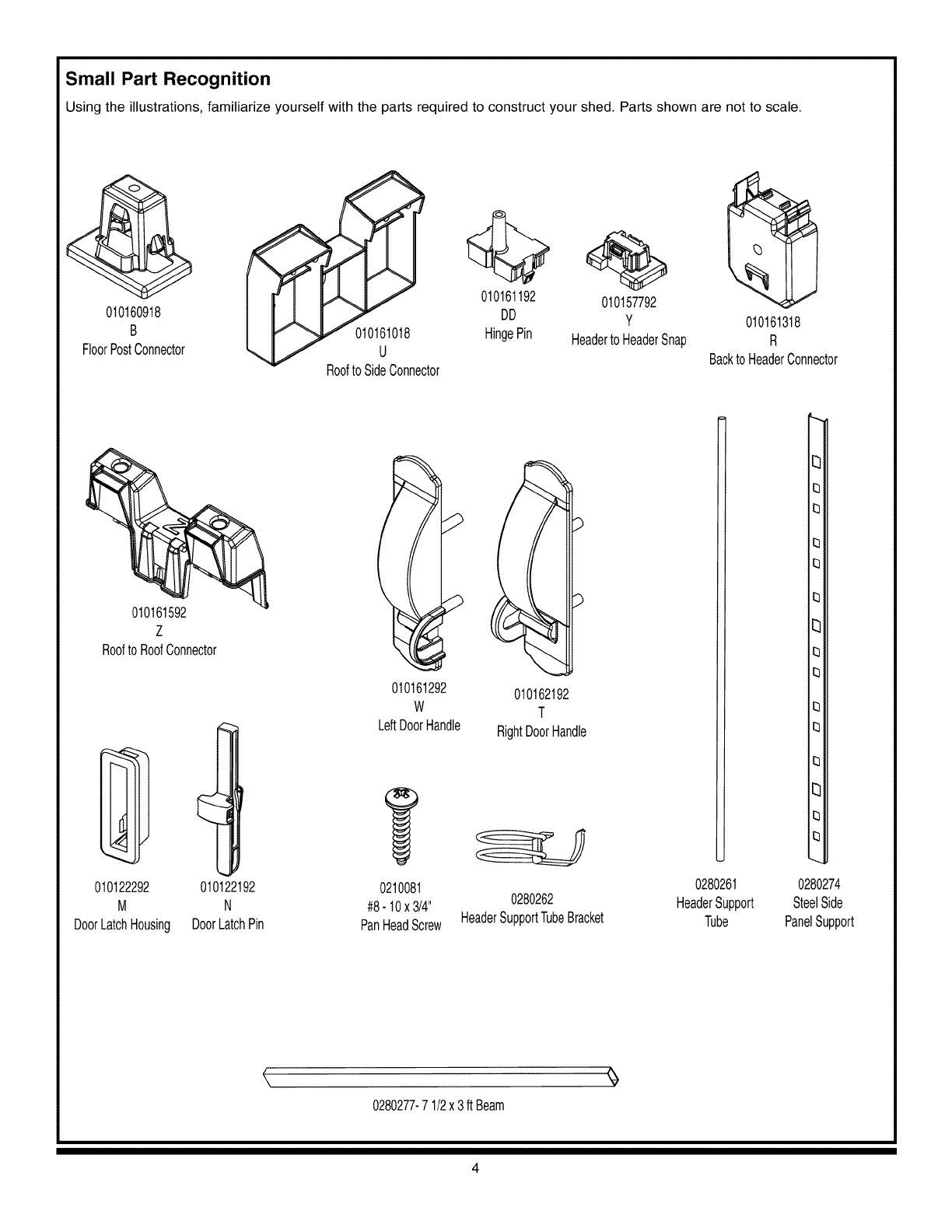
Small Part Recognition
Using the illustrations, familiarize yourself with the parts required to construct your shed. Parts shown are not to scale.
01o7918I
FloorPostConnector
l
8
RooftoSideConnector
010161192 010157792
DD y 010161318
HingePin Headerto HeaderSnap R
BacktoHeaderConnector
010161592
Z
RooftoRoofConnector
010122292 010122192
M N
DoorLatchHousing DoorLatchPin
010161292 010162192
W T
LeftDoorHandle RightDoorHandle
0210081
#8- 10x 3/4" 0280262
PanHeadScrew HeaderSupportTubeBracket
0280261
HeaderSupport
Tube
[3
13
13
13
13
13
[3
13
13
13
13
13
[3
13
13
0280274
SteelSide
PanelSupport
<,
0280277-71/2x 3ft Beam
4
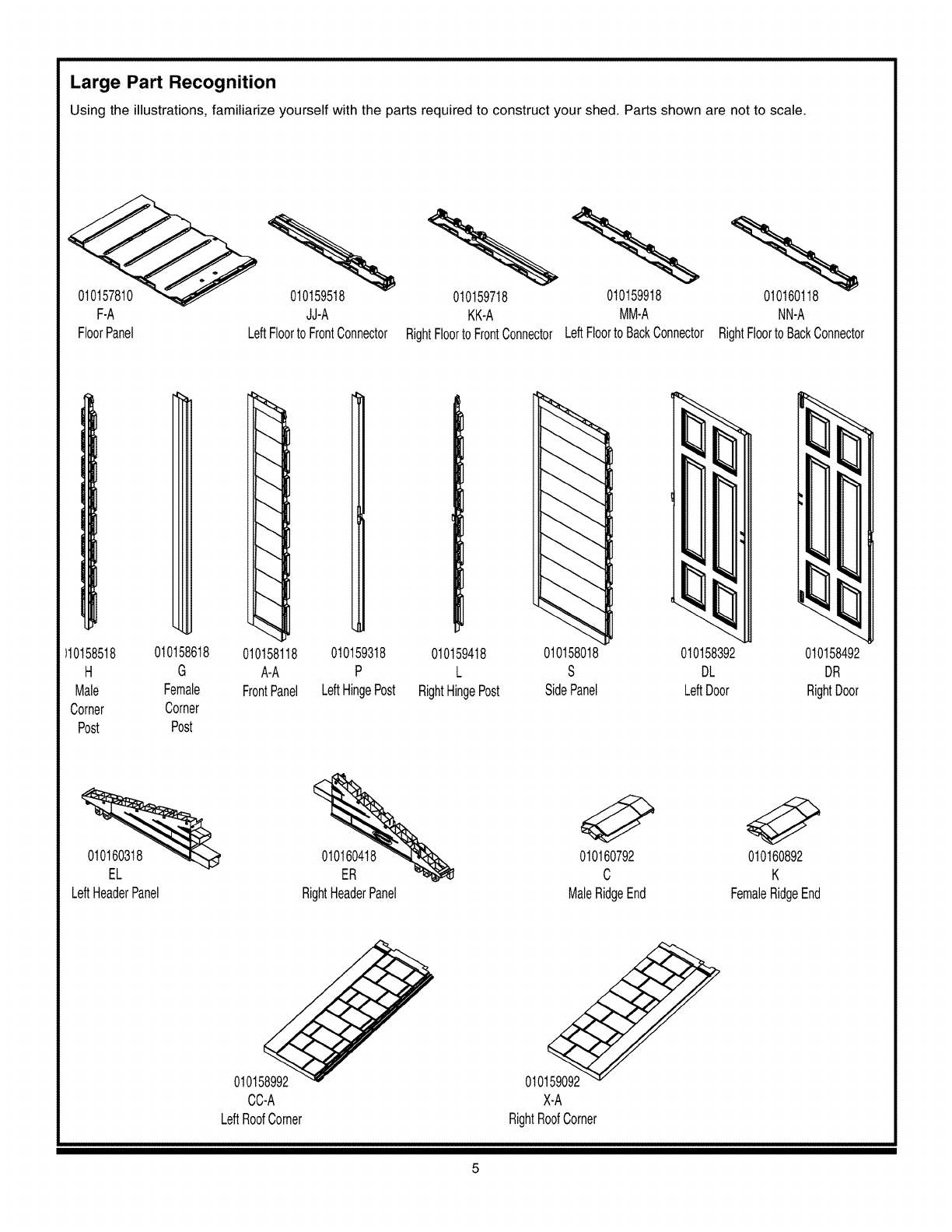
Large Part Recognition
Using the illustrations, familiarize yourself withthe parts required to construct your shed. Parts shown are not to scale,
F-A JJ-A
FloorPanel LeftFloortoFrontConnector
010159718 010159918 010160118
KK-A MM-A NN-A
RightFloortoFrontConnectorLeftFloortoBackConnector RightFloortoBackConnector
)10158518 010158618 010159318
H G P
Male Female LeftHingePost
Corner Corner
Post Post
010158118
A-A
FrontPanel
010159418 010158392 010158492
L DL DR
RightHingePost LeftDoor RightDoor
010158018
S
SidePanel
010160318 010160418
EL ER
LeftHeaderPanel RightHeaderPanel
010160792 010160892
C K
MaleRidgeEnd FemaleRidgeEnd
o
CC-A
LeftRoofCorner
010159092
X-A
RightRoofCorner
5
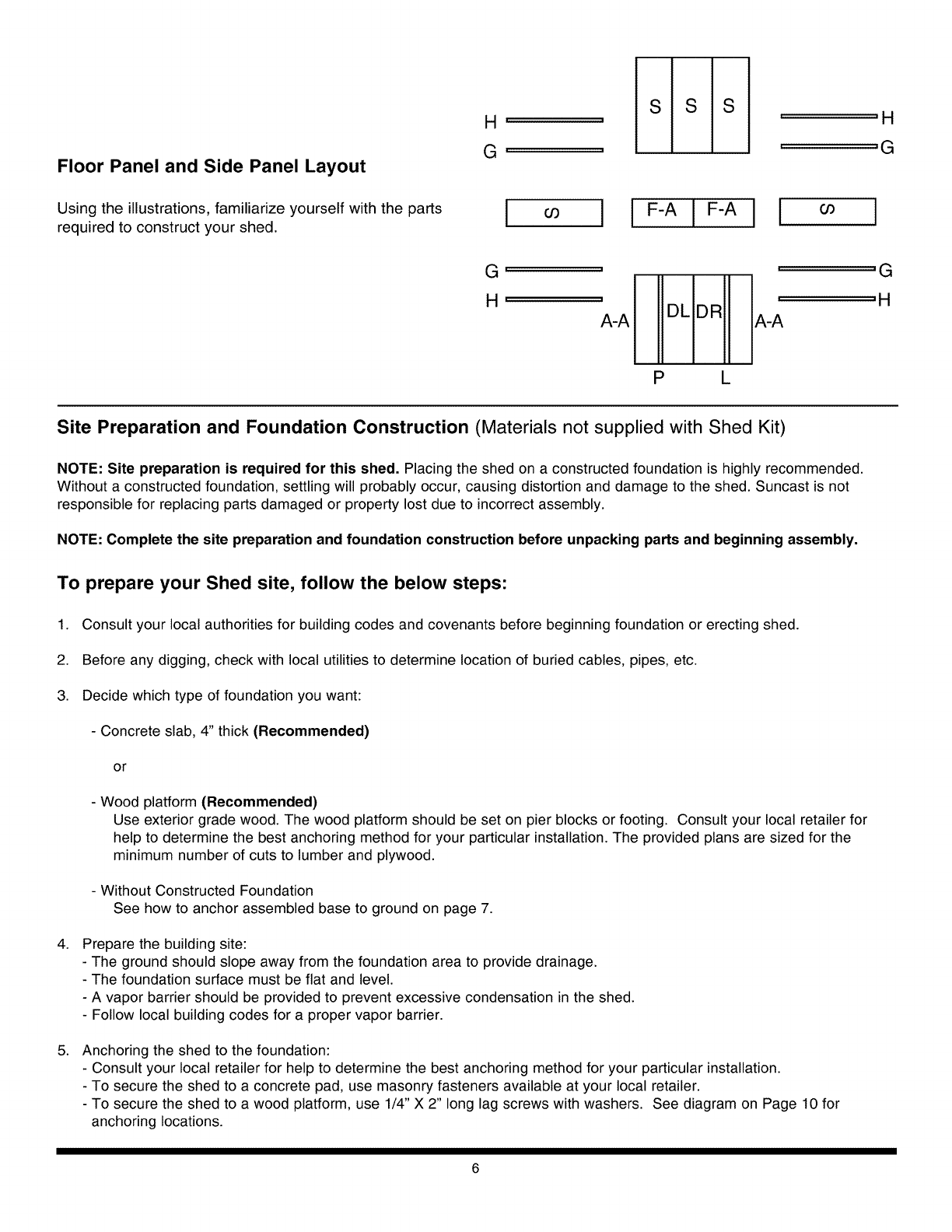
Floor Panel and Side Panel Layout
Using the illustrations, familiarize yourself with the parts
required to construct your shed. !IIF-AIFAII I
G,
H'
A-A
''G
' 'H
A-A
P L
Site Preparation and Foundation Construction (Materials not supplied with Shed Kit)
NOTE: Site preparation is required for this shed. Placing the shed on a constructed foundation is highly recommended.
Without a constructed foundation, settling will probably occur, causing distortion and damage to the shed. Suncast is not
responsible for replacing parts damaged or property lost due to incorrect assembly.
NOTE: Complete the site preparation and foundation construction before unpacking parts and beginning assembly.
To prepare your Shed site, follow the below steps:
1. Consult your local authorities for building codes and covenants before beginning foundation or erecting shed.
2. Before any digging, check with local utilities to determine location of buried cables, pipes, etc.
3. Decide which type of foundation you want:
- Concrete slab, 4" thick (Recommended)
or
4,
5.
- Wood platform (Recommended)
Use exterior grade wood. The wood platform should be set on pier blocks or footing. Consult your local retailer for
help to determine the best anchoring method for your particular installation. The provided plans are sized for the
minimum number of cuts to lumber and plywood.
- Without Constructed Foundation
See how to anchor assembled base to ground on page 7.
Prepare the building site:
- The ground should slope away from the foundation area to provide drainage.
- The foundation surface must be flat and level.
- A vapor barrier should be provided to prevent excessive condensation in the shed.
- Follow local building codes for a proper vapor barrier.
Anchoring the shed to the foundation:
- Consult your local retailer for help to determine the best anchoring method for your particular installation.
- To secure the shed to a concrete pad, use masonry fasteners available at your local retailer.
- To secure the shed to a wood platform, use 1/4" X 2" long lag screws with washers. See diagram on Page 10 for
anchoring locations.
6
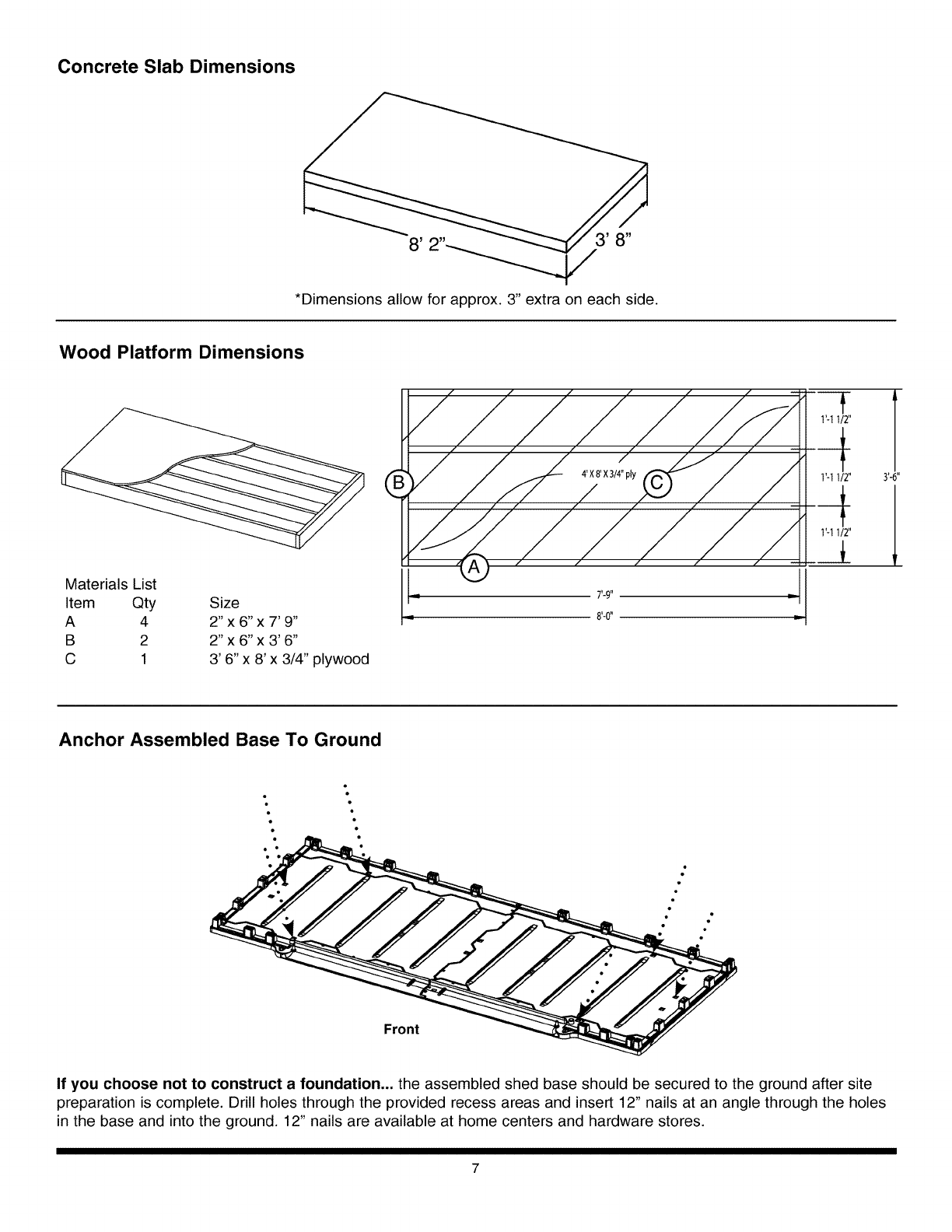
Concrete Slab Dimensions
*Dimensions allow for approx. 3" extra on each side.
Wood Platform Dimensions
II f f [ fff_ T
iate rials _4t_ S,1,_6,,x 7, 9,' L__////// z///z_/z__ _
B 2 2" x 6" x 3' 6"
C 1 3' 6"x 8' x 3/4" plywood
Anchor Assembled Base To Ground
-:
.- ....
If you choose not to construct a foundation.., the assembled shed base should be secured to the ground after site
preparation is complete. Drill holes through the provided recess areas and insert 12" nails at an angle through the holes
in the base and into the ground. 12" nails are available at home centers and hardware stores.
7
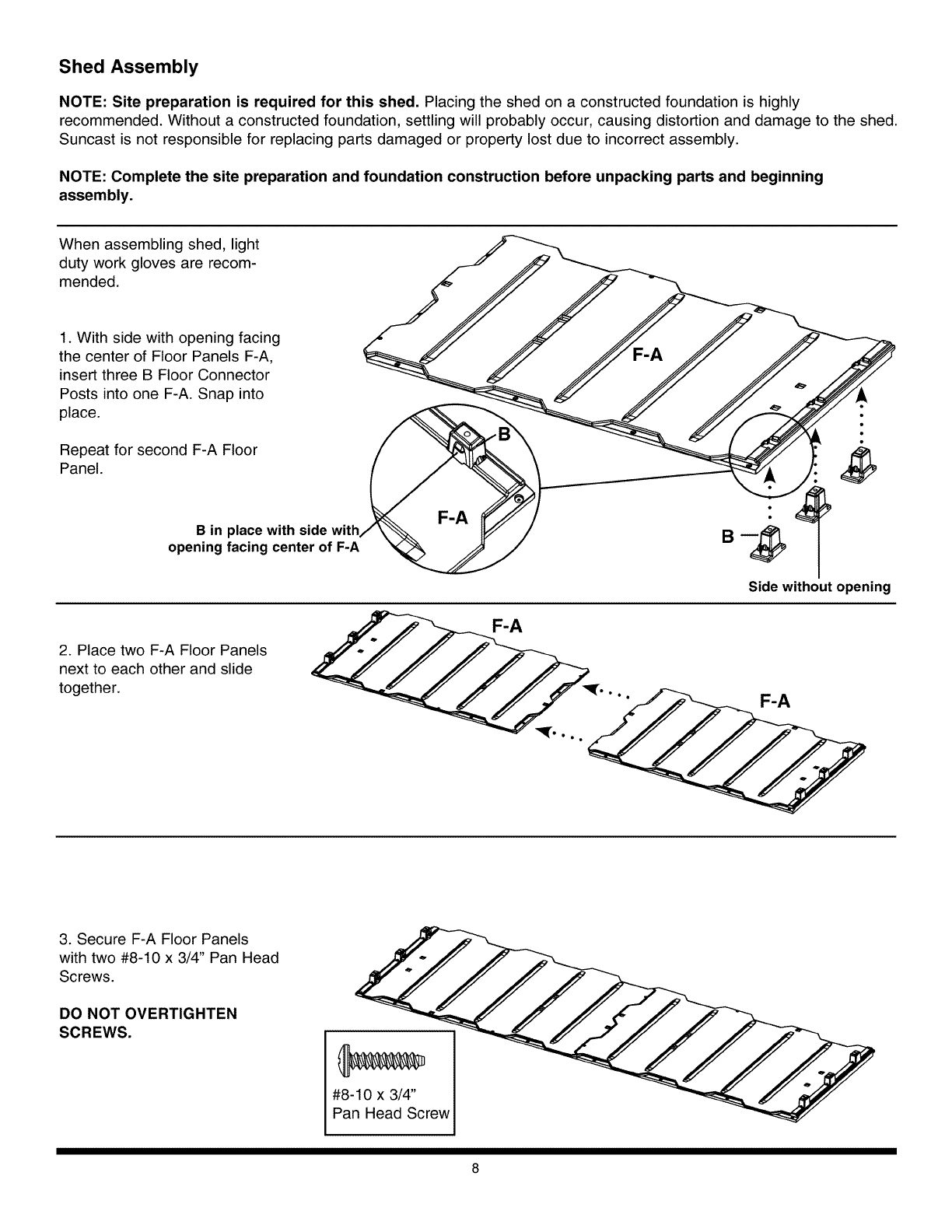
Shed Assembly
NOTE: Site preparation is required for this shed. Placing the shed on a constructed foundation is highly
recommended. Without a constructed foundation, settling will probably occur, causing distortion and damage to the shed.
Suncast is not responsible for replacing parts damaged or property lost due to incorrect assembly.
NOTE: Complete the site preparation and foundation construction before unpacking parts and beginning
assembly.
When assembling shed, light
duty work gloves are recom-
mended.
1. With side with opening facing
the center of Floor Panels F-A,
insert three B Floor Connector
Posts into one F-A. Snap into
place.
Repeat for second F-A Floor
Panel.
/
B in place with side with
opening facing center of F-A
Side without opening
2. Place two F-A Floor Panels
next to each other and slide
together.
F-A
3. Secure F-A Floor Panels
with two #8-10 x 3/4" Pan Head
Screws.
DO NOT OVERTIGHTEN
SCREWS.
#8-10 x 3/4"
Pan Head Screw
8
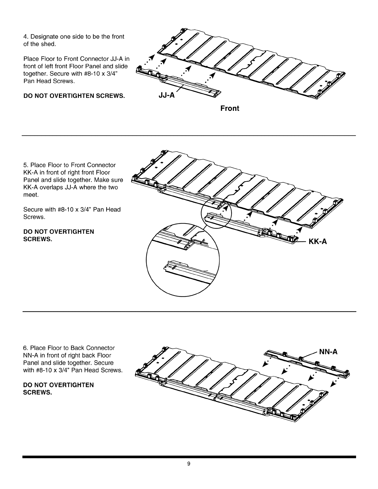
4. Designate one side to be the front
of the shed.
Place Floor to Front Connector JJ-A in
front of left front Floor Panel and slide
together. Secure with #8-10 x 3/4"
Pan Head Screws.
DO NOT OVERTIGHTEN SCREWS.
Front
5. Place Floor to Front Connector
KK-A in front of right front Floor
Panel and slide together. Make sure
KK-A overlaps JJ-A where the two
meet.
Secure with #8-10 x 3/4" Pan Head
Screws.
DO NOT OVERTIGHTEN
SCREWS. KK-A
6. Place Floor to Back Connector
NN-A in front of right back Floor
Panel and slide together. Secure
with #8-10 x 3/4" Pan Head Screws.
DO NOT OVERTIGHTEN
SCREWS.
_NN-A
.
9
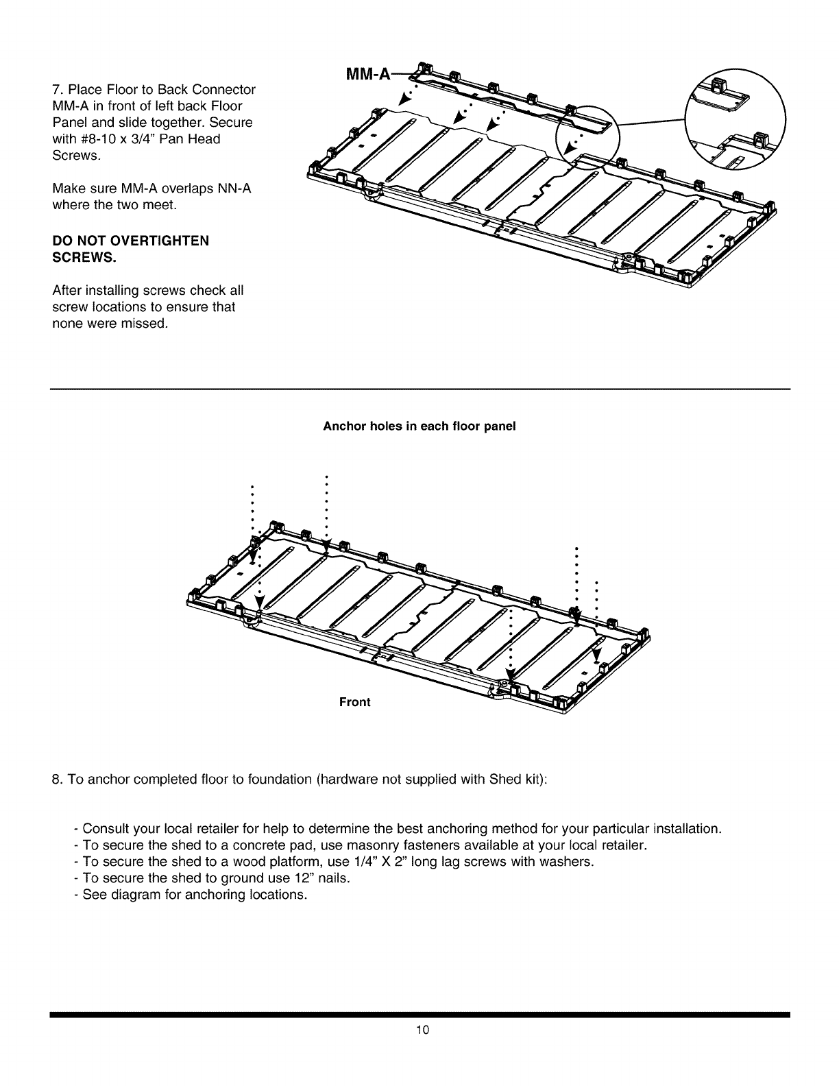
7. Place Floor to Back Connector
MM-A in front of left back Floor
Panel and slide together. Secure
with #8-10 x 3/4" Pan Head
Screws.
Make sure MM-A overlaps NN-A
where the two meet.
DO NOT OVERTIGHTEN
SCREWS.
After installing screws check all
screw locations to ensure that
none were missed.
Anchor holes in each floor panel
: •
8. To anchor completed floor to foundation (hardware not supplied with Shed kit):
- Consult your local retailer for help to determine the best anchoring method for your particular installation.
- To secure the shed to a concrete pad, use masonry fasteners available at your local retailer.
- To secure the shed to a wood platform, use 1/4" X 2" long lag screws with washers.
- To secure the shed to ground use 12" nails.
- See diagram for anchoring locations.
10
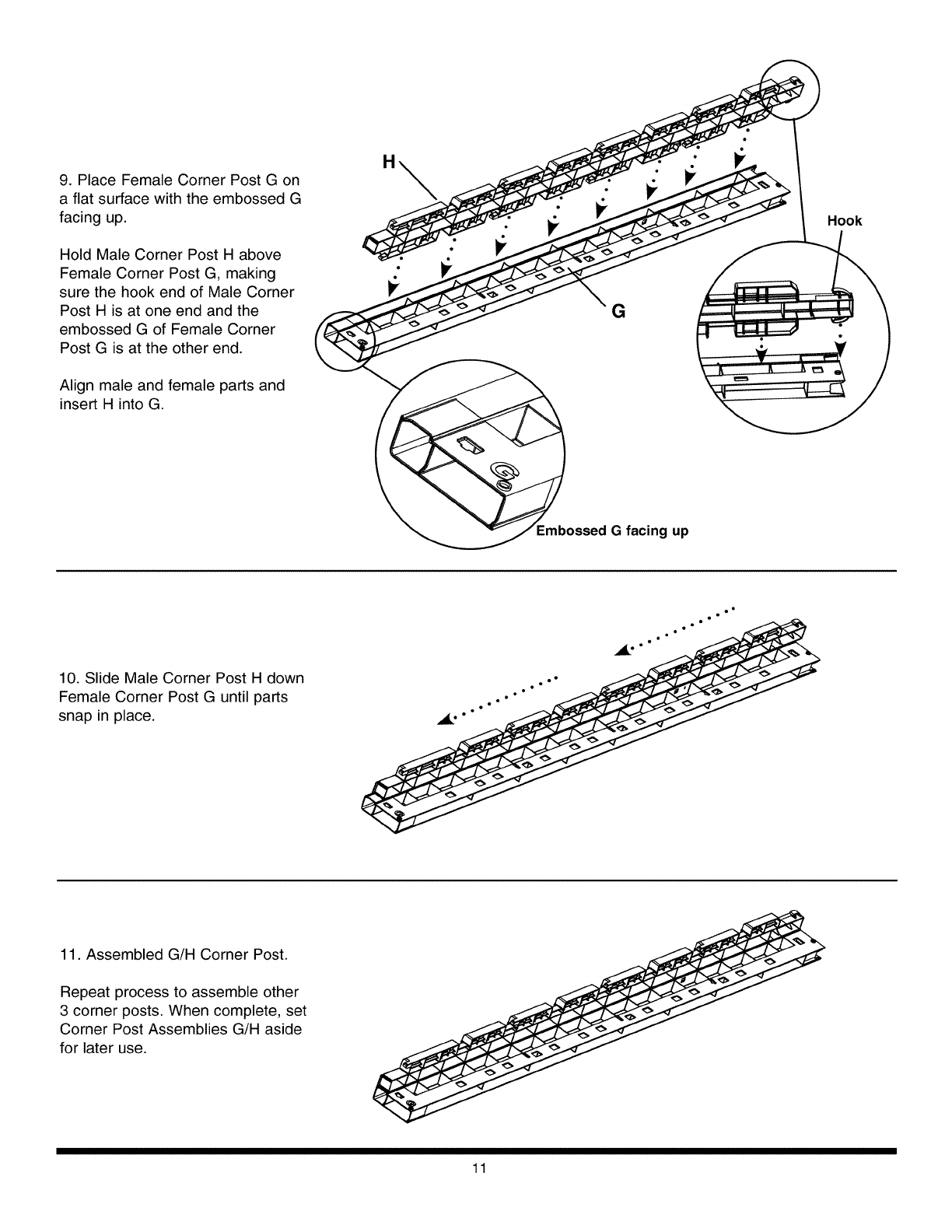
9. Place Female Corner Post G on
a flat surface with the embossed G
facing up.
Hold Male Corner Post H above
Female Corner Post G, making
sure the hook end of Male Corner
Post H is at one end and the
embossed G of Female Corner
Post G is at the other end.
Align male and female parts and
insert H into G.
H
ossed G facing up
Hook
10. Slide Male Corner Post H down
Female Corner Post G until parts
snap in place.
•l
11. Assembled G/H Corner Post.
Repeat process to assemble other
3 corner posts. When complete, set
Corner Post Assemblies G/H aside
for later use.
11
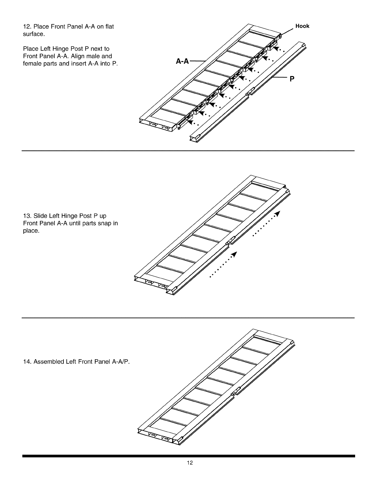
12. Place Front Panel A-A on flat
surface.
Place Left Hinge Post P next to
Front Panel A-A. Align male and
female parts and insert A-A into P.
__= ._/ Hook
13. Slide Left Hinge Post P up
Front Panel A-A until parts snap in
place.
14. Assembled Left Front Panel A-A/P.
12
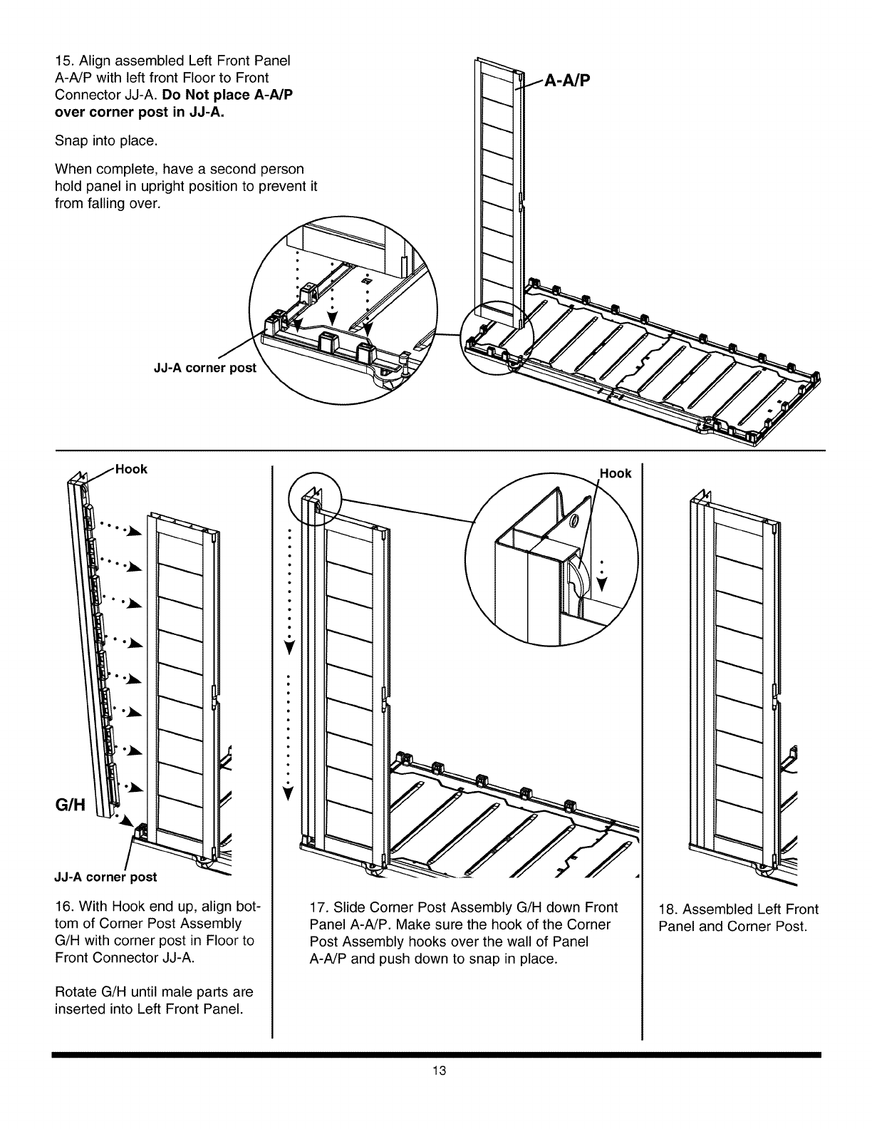
15. Align assembled Left Front Panel
A-A/P with left front Floor to Front
Connector JJ-A. Do Not place A-NP
over corner post in JJ-A.
Snap into place.
When complete, have a second person
hold panel in upright position to prevent it
from falling over.
JJ-A corner post
J
J
J
,j
G/H
JJ-A corner )ost
16. With Hook end up, align bot-
tom of Corner Post Assembly
G/H with corner post in Floor to
Front Connector JJ-A.
Rotate G/H until male parts are
inserted into Left Front Panel.
J
Hook
!
17. Slide Corner Post Assembly G/H down Front
Panel A-A/P. Make sure the hook of the Corner
Post Assembly hooks over the wall of Panel
A-A/P and push down to snap in place.
18. Assembled Left Front
Panel and Corner Post.
13
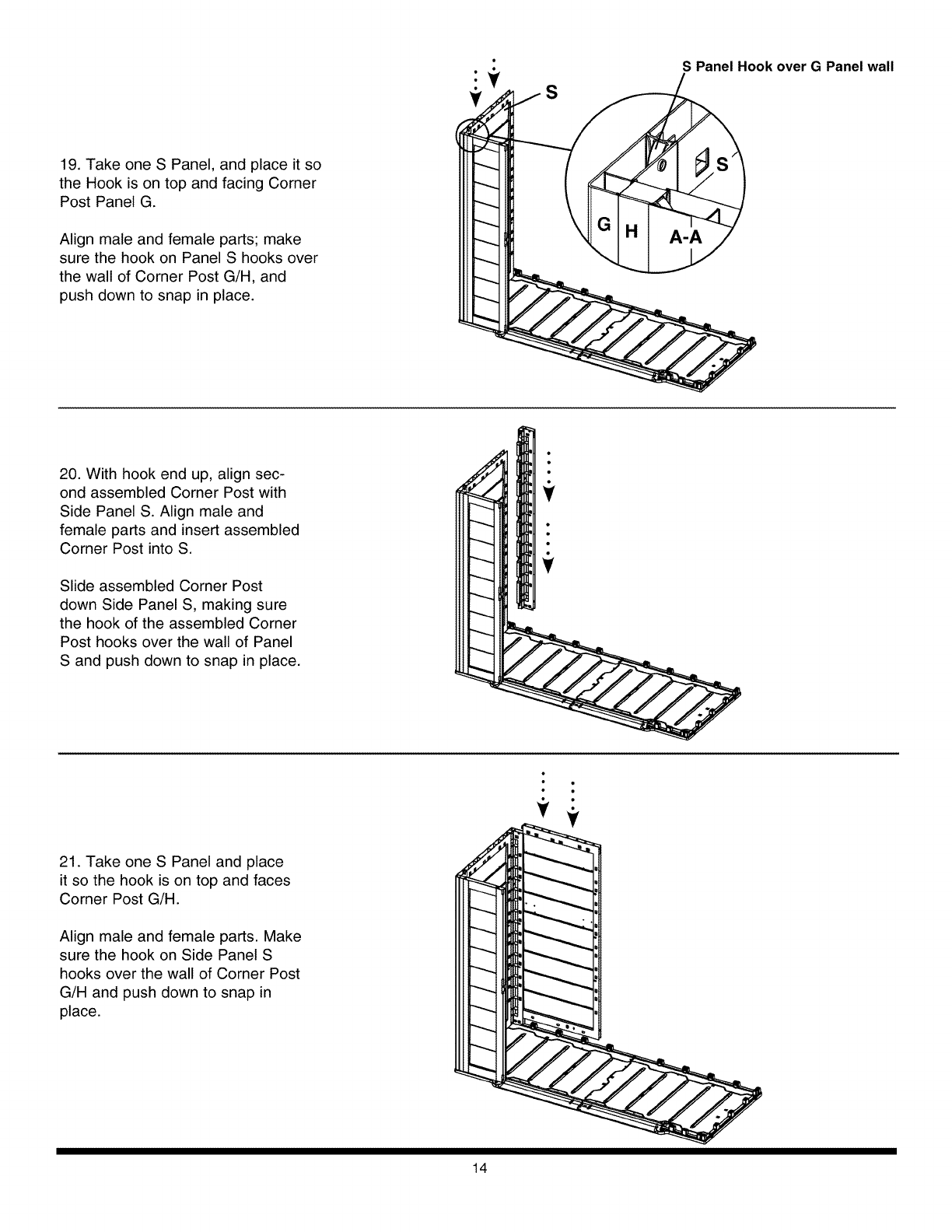
19. Take one S Panel, and place it so
the Hook is on top and facing Corner
Post Panel G.
Align male and female parts; make
sure the hook on Panel S hooks over
the wall of Corner Post G/H, and
push down to snap in place.
S
S Panel Hook over G Panel wall
20. With hook end up, align sec-
ond assembled Corner Post with
Side Panel S. Align male and
female parts and insert assembled
Corner Post into S.
Slide assembled Corner Post
down Side Panel S, making sure
the hook of the assembled Corner
Post hooks over the wall of Panel
S and push down to snap in place.
21. Take one S Panel and place
it so the hook is on top and faces
Corner Post G/H.
Align male and female parts. Make
sure the hook on Side Panel S
hooks over the wall of Corner Post
G/H and push down to snap in
place.
14
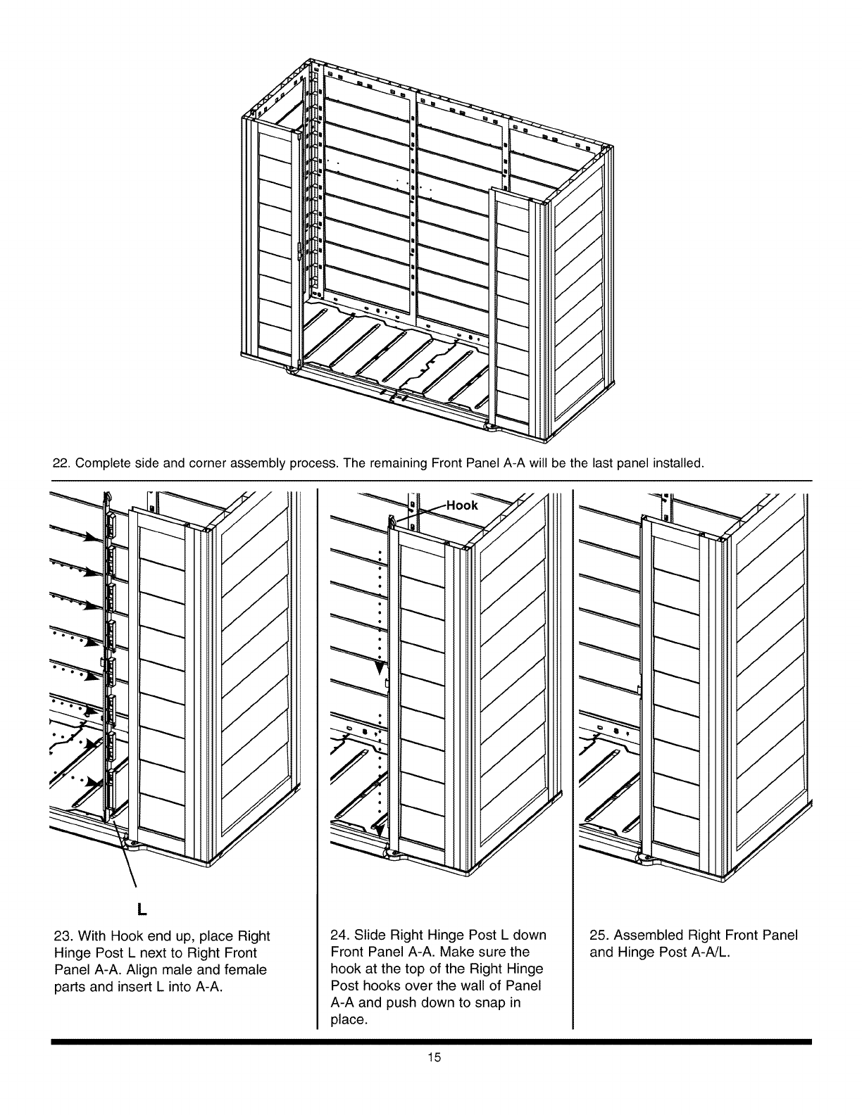
22.Completesideandcornerassemblyprocess.TheremainingFrontPanelA-Awillbethelastpanelinstalled.
L
23. With Hook end up, place Right 24. Slide Right Hinge Post L down
Hinge Post L next to Right Front Front Panel A-A. Make sure the
Panel A-A. Align male and female hook at the top of the Right Hinge
parts and insert L into A-A. Post hooks over the wall of Panel
A-A and push down to snap in
place.
25. Assembled Right Front Panel
and Hinge Post A-A/L.
15
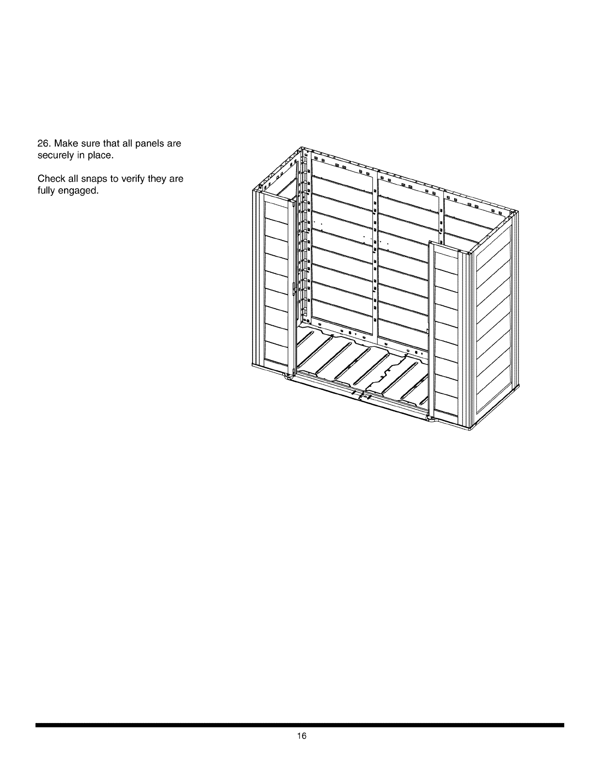
26. Make sure that all panels are
securely in place.
Check all snaps to verify they are
fully engaged.
16
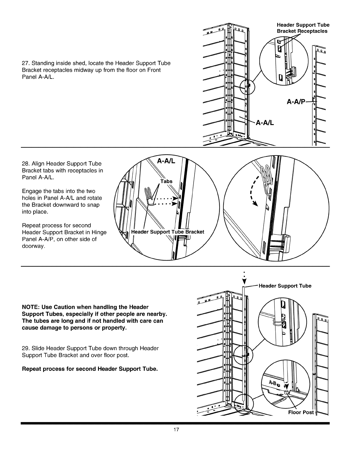
27. Standing inside shed, locate the Header Support Tube
Bracket receptacles midway up from the floor on Front
Panel A-A/L.
28. Align Header Support Tube
Bracket tabs with receptacles in
Panel A-A/L.
Engage the tabs into the two
holes in Panel A-A/L and rotate
the Bracket downward to snap
into place.
Repeat process for second
Header Support Bracket in Hinge
Panel A-A/P, on other side of
doorway.
NOTE: Use Caution when handling the Header
Support Tubes, especially if other people are nearby.
The tubes are long and if not handled with care can
cause damage to persons or property.
29. Slide Header Support Tube down through Header
Support Tube Bracket and over floor post.
Repeat process for second Header Support Tube.
17
Header Support Tube
Bracket Receptacles
A-A/P --
Y-_Header Support Tube
Q_
Floor Post
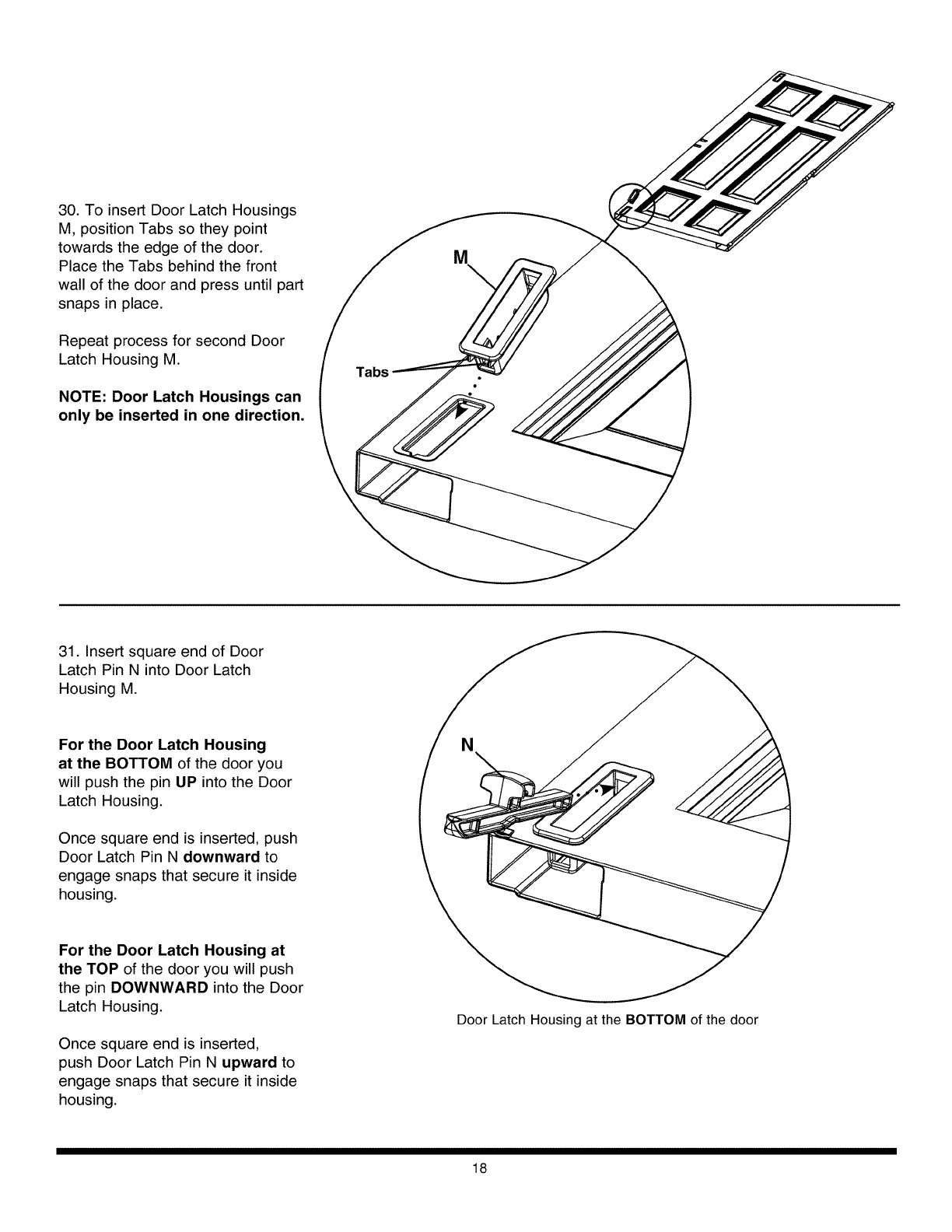
30. To insert Door Latch Housings
M, position Tabs so they point
towards the edge of the door.
Place the Tabs behind the front
wall of the door and press until part
snaps in place.
Repeat process for second Door
Latch Housing M.
NOTE: Door Latch Housings can
only be inserted in one direction.
Tabs
M
31. Insert square end of Door
Latch Pin N into Door Latch
Housing M.
For the Door Latch Housing
at the BOTTOM of the door you
will push the pin UP into the Door
Latch Housing.
Once squa_ endisinserted, push
Door Latch Pin N downward to
engage snapsthatsecureitinside
housing.
For the Door Latch Housing at
the TOP of the door you will push
the pin DOWNWARD into the Door
Latch Housing.
Once square end is inserted,
push Door Latch Pin N upward to
engage snaps that secure it inside
housing.
Door Latch Housing at the BOTTOM of the door
18
Receptacle in A-A/L
DR
Lower Hinge Post
A-A/L
KK-A
32. With Door DR in the closed position, align Mid Hinge
Post with receptacle in Assembled Right Front Panel A-A/L
At the same time, align Lower Hinge Post of Front Connector
KK-A with receptacle in Right Door DR and slide down into
place.
33. With Right Door in open position,
repeat process for Left Door DL.
19
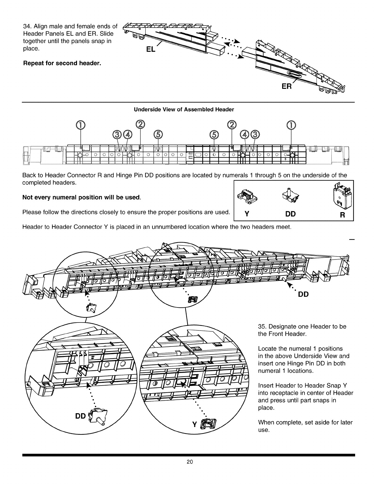
34. Align male and female ends of
Header Panels EL and ER. Slide
together until the panels snap in
place.
Repeat for second header.
ER
Underside View of Assembled Header
Back to Header Connector R and Hinge Pin DD positions are located by numerals 1 through 5 on the underside of the
completed headers.
Not every numeral position will be used. _ 1_
Please follow the directions closely to ensure the proper positions are used. y DD
Header to Header Connector Y is placed in an unnumbered location where the two headers meet.
DD
DD
Y
35. Designate one Header to be
the Front Header.
Locate the numeral 1 positions
in the above Underside View and
insert one Hinge Pin DD in both
numeral 1 locations.
Insert Header to Header Snap Y
into receptacle in center of Header
and press until part snaps in
place.
When complete, set aside for later
use.
2O
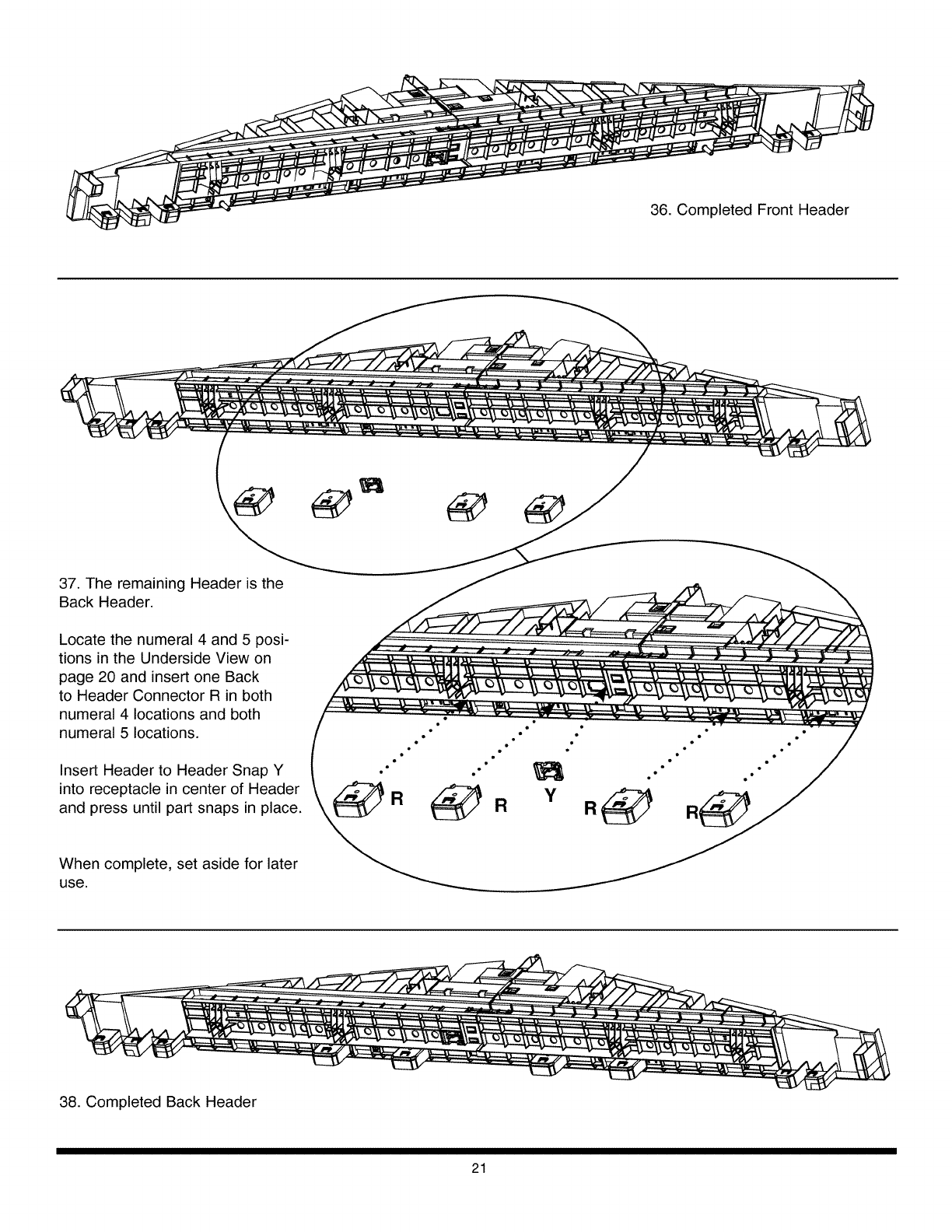
36. Completed Front Header
37. The remaining Header is the
Back Header.
Locate the numeral 4 and 5 posi-
tions in the Underside View on
page 20 and insert one Back
to Header Connector R in both
numeral 4 locations and both
numeral 5 locations.
Insert Header to Header Snap Y
into receptacle in center of Header
and press until part snaps in place.
When complete, set aside for later
use.
38. Completed Back Header
21
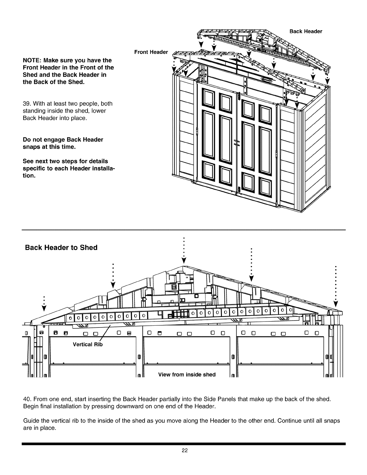
NOTE: Make sure you have the
Front Header in the Front of the
Shed and the Back Header in
the Back of the Shed.
39. With at least two people, both
standing inside the shed, lower
Back Header into place.
Do not engage Back Header
snaps at this time.
See next two steps for details
specific to each Header installa-
tion.
Front Header
Back Header
Back Header to Shed
÷
IB IB 0 0
Vertical Rib
0 B 0 I_ 0 0 0 0 0 0 0 0 [] 0
View from inside shed
40. From one end, start inserting the Back Header partially into the Side Panels that make up the back of the shed.
Begin final installation by pressing downward on one end of the Header.
Guide the vertical rib to the inside of the shed as you move along the Header to the other end. Continue until all snaps
are in place.
22
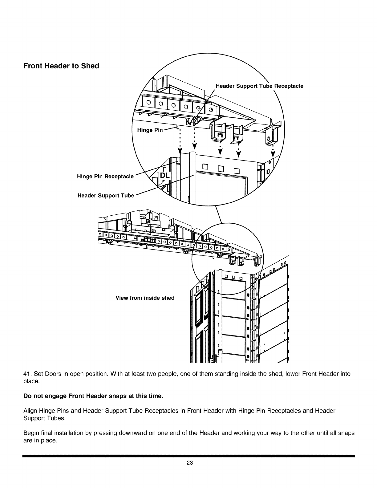
Front Header to Shed
Header Support Tube Receptacle
Hinge Pin Receptacle
Header SupportTube
Hinge Pin
•,÷ ÷
View from inside shed
41. Set Doors in open position. With at least two people, one of them standing inside the shed, lower Front Header into
place.
Do not engage Front Header snaps at this time.
Align Hinge Pins and Header Support Tube Receptacles in Front Header with Hinge Pin Receptacles and Header
Support Tubes.
Begin final installation by pressing downward on one end of the Header and working your way to the other until all snaps
are in place.
23
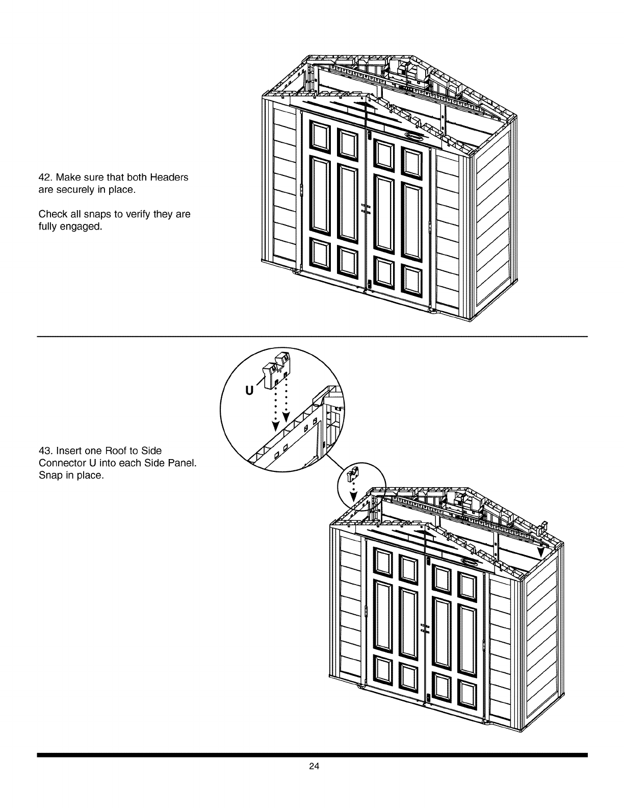
42. Make sure that both Headers
are securely in place.
Check all snaps to verify they are
fully engaged.
43. Insert one Roof to Side
Connector U into each Side Panel.
Snap in place.
24
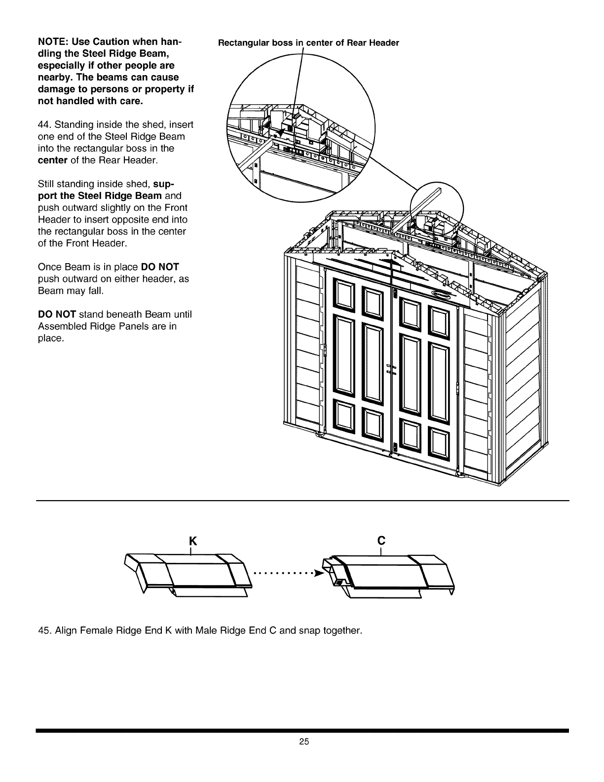
NOTE: Use Caution when han-
dling the Steel Ridge Beam,
especially if other people are
nearby. The beams can cause
damage to persons or property if
not handled with care.
44. Standing inside the shed, insert
one end of the Steel Ridge Beam
into the rectangular boss in the
center of the Rear Header.
Still standing inside shed, sup-
port the Steel Ridge Beam and
push outward slightly on the Front
Header to insert opposite end into
the rectangular boss in the center
of the Front Header.
Once Beam is in place DO NOT
push outward on either header, as
Beam may fall.
DO NOT stand beneath Beam until
Assembled Ridge Panels are in
place.
Rectangular boss in center of Rear Header
K
IC
I
45. Align Female Ridge End K with Male Ridge End C and snap together.
25
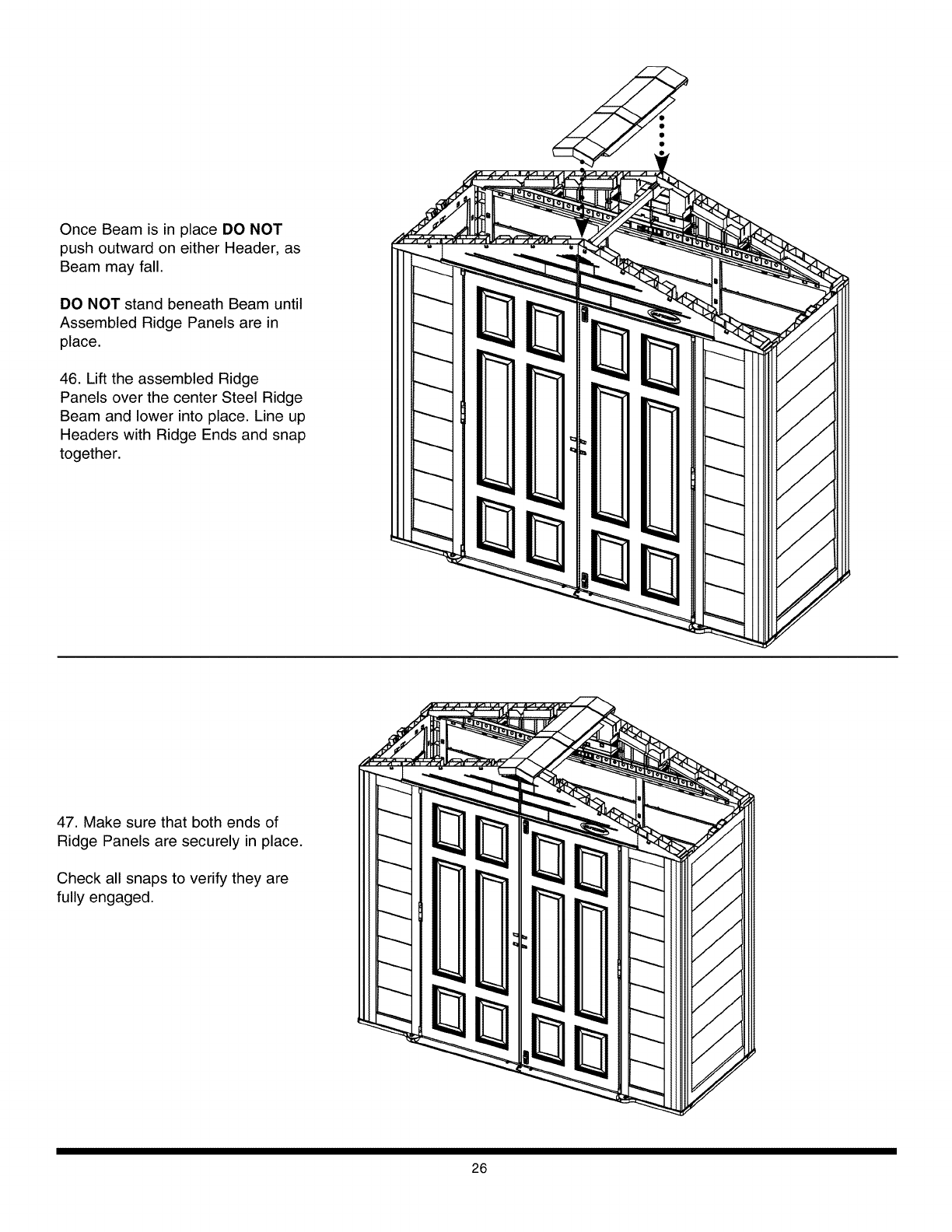
Once Beam is in place DO NOT
push outward on either Header, as
Beam may fall.
DO NOT stand beneath Beam until
Assembled Ridge Panels are in
place.
46. Lift the assembled Ridge
Panels over the center Steel Ridge
Beam and lower into place. Line up
Headers with Ridge Ends and snap
together.
47. Make sure that both ends of
Ridge Panels are securely in place.
Check all snaps to verify they are
fully engaged.
26
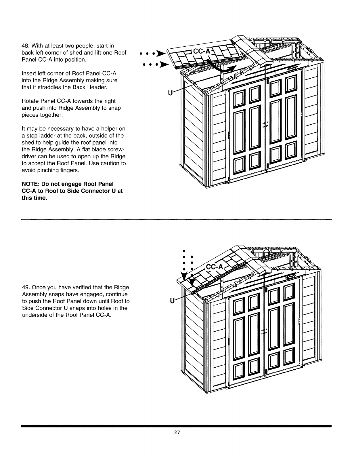
48. With at least two people, start in
back left corner of shed and lift one Roof
Panel CC-A into position.
Insert left corner of Roof Panel CC-A
into the Ridge Assembly making sure
that it straddles the Back Header.
Rotate Panel CC-A towards the right
and push into Ridge Assembly to snap
pieces together.
It may be necessary to have a helper on
a step ladder at the back, outside of the
shed to help guide the roof panel into
the Ridge Assembly. A flat blade screw-
driver can be used to open up the Ridge
to accept the Roof Panel. Use caution to
avoid pinching fingers.
NOTE: Do not engage Roof Panel
CC-A to Roof to Side Connector U at
this time.
••0_
49. Once you have verified that the Ridge
Assembly snaps have engaged, continue
to push the Roof Panel down until Roof to
Side Connector U snaps into holes in the
underside of the Roof Panel CC-A.
• •
• •
U
27
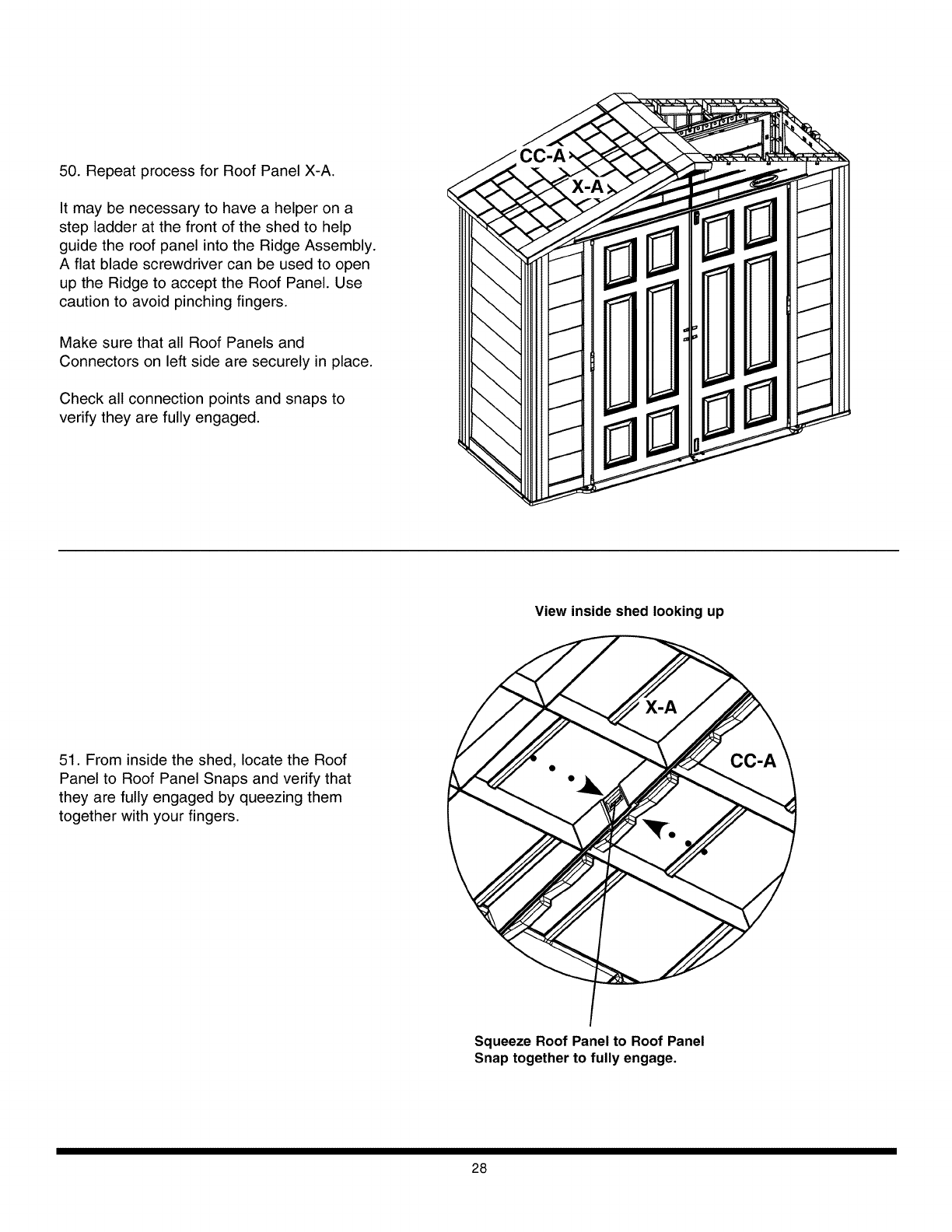
50. Repeat process for Roof Panel X-A.
It may be necessary to have a helper on a
step ladder at the front of the shed to help
guide the roof panel into the Ridge Assembly.
A flat blade screwdriver can be used to open
up the Ridge to accept the Roof Panel. Use
caution to avoid pinching fingers.
Make sure that all Roof Panels and
Connectors on left side are securely in place.
Check all connection points and snaps to
verify they are fully engaged.
View inside shed looking up
51. From inside the shed, locate the Roof
Panel to Roof Panel Snaps and verify that
they are fully engaged by queezing them
together with your fingers.
Squeeze Roof Panel to Roof Panel
Snap together to fully engage.
28
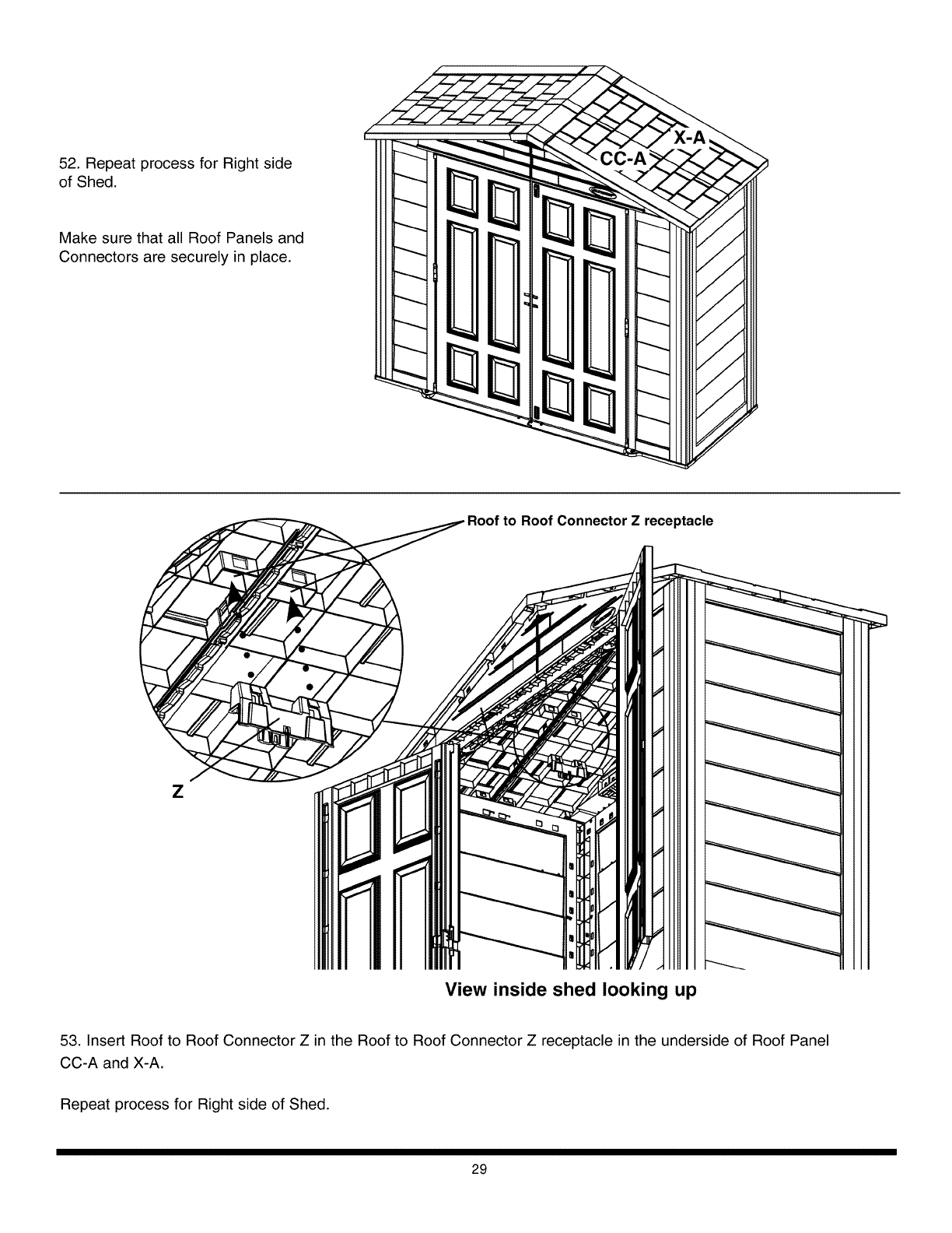
52. Repeat process for Right side
of Shed.
(
Make sure that all Roof Panels and
Connectors are securely in place.
to Roof Connector Z receptacle
Z
View inside shed looking up
53. Insert Roof to Roof Connector Z in the Roof to Roof Connector Z receptacle in the underside of Roof Panel
CC-A and X-A.
Repeat process for Right side of Shed.
29
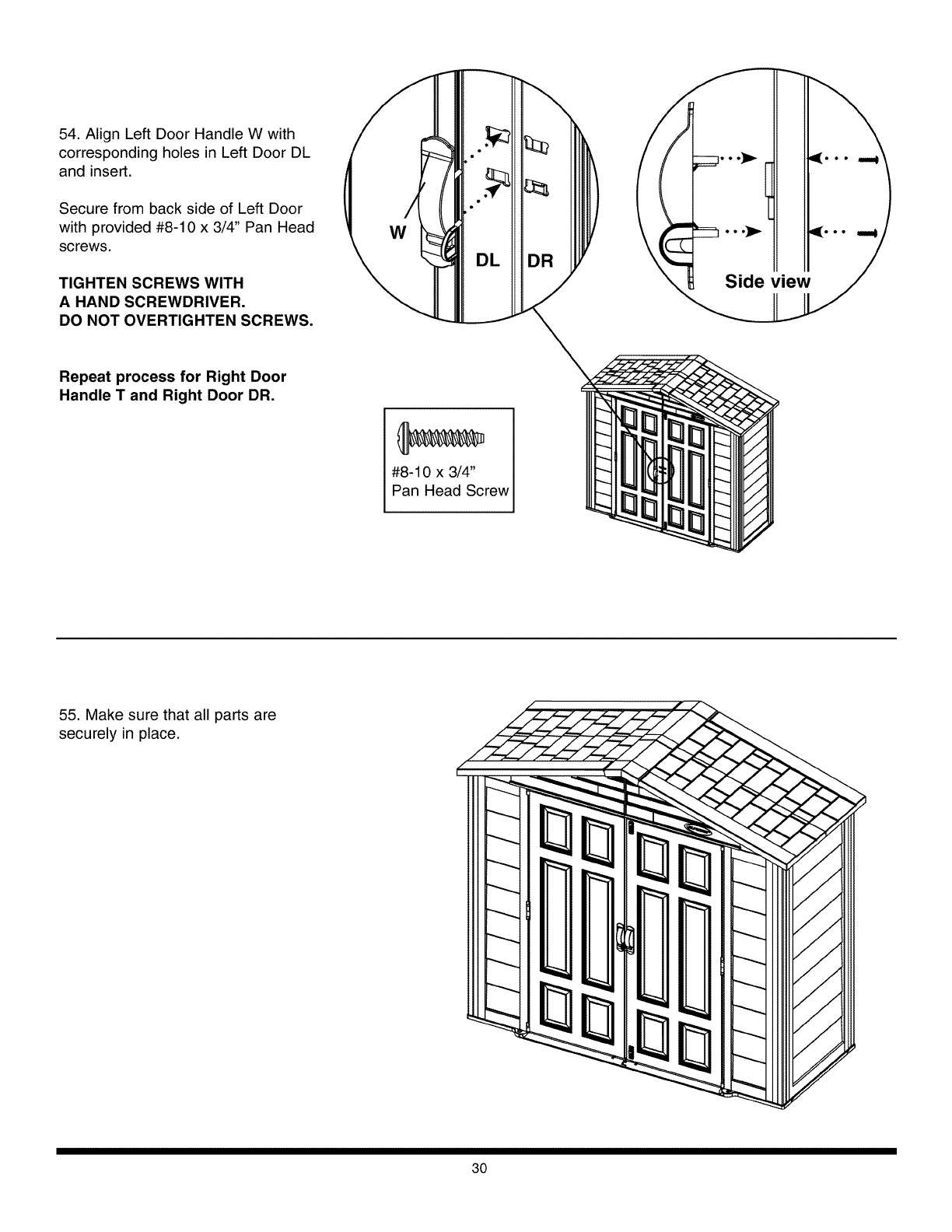
54. Align Left Door Handle W with
corresponding holes in Left Door DL
and insert.
Secure from back side of Left Door
with provided #8-10 x 3/4" Pan Head
screws.
TIGHTEN SCREWS WITH
A HAND SCREWDRIVER.
DO NOT OVERTIGHTEN SCREWS,
/
W
D
Repeat process for Right Door
Handle Tand Right Door DR.
#8-10 x 3/4"
Pan Head Screw
55. Make sure that all parts are
securely in place.
(
30
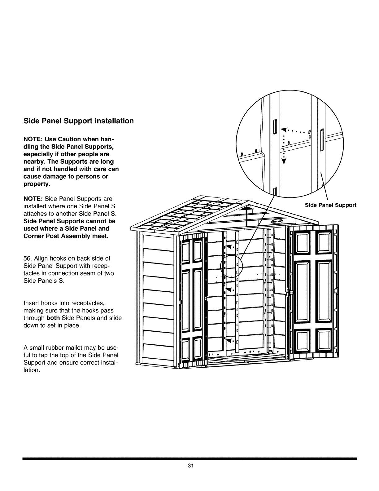
Side Panel Support installation
NOTE: Use Caution when han-
dling the Side Panel Supports,
especially if other people are
nearby. The Supports are long
and if not handled with care can
cause damage to persons or
property.
NOTE: Side Panel Supports are
installed where one Side Panel S
attaches to another Side Panel S.
Side Panel Supports cannot be
used where a Side Panel and
Corner Post Assembly meet.
Side Panel Support
56. Align hooks on back side of
Side Panel Support with recep-
tacles in connection seam of two
Side Panels S.
Insert hooks into receptacles,
making sure that the hooks pass
through both Side Panels and slide
down to set in place.
A small rubber mallet may be use-
ful to tap the top of the Side Panel
Support and ensure correct instal-
lation.
31
Suncast®Corporation,701NorthKirkRoad,Batavia,Illinois60510(Manufacturer)warrantstotheoriginalpurchaseronlythattheenclosedproduct
isfreefrommaterialandworkmanshipdefectsundernormal,householduseattimeofpurchase.Defectiveproductorpartmustbereturned,freight
prepaid,totheManufacturer'saddress(Attention:PartsDepartment)alongwithproofofpurchase.Uponreceiptoftheaforesaid,thedefectiveprod-
uctorpartwillberepairedorreplacedattheoptionoftheManufacturerwithoutchargetotheoriginalpurchaserandreturnedtothecustomerfreight
collect.
Thislimitedwarrantydoesnotapplytodamageresultingfromaccident,neglect,misuse,commercialuse,alteration,operationnotinaccordancewith
instructionorrepairsmadeorattemptedbyunauthorizedpersons.
Thislimitedwarrantyappliesonlytotheproductenclosedanddoesnotapplytoaccessoryparts.
THEMANUFACTURER'SLIABILITYHEREUNDERISLIMITEDSOLELYTOTHEREPAIRORREPLACEMENTOFTHEDEFECTIVEPRODUCTORPART
ANDTHEMANUFACTURERSHALLINNOEVENTBELIABLEFORANYINCIDENTALORCONSEQUENTIALDAMAGESWHICHMAYRESULTFROMANY
DEFECTINMATERIALORWORKMANSHIPORFROMTHEBREACHOFANYEXPRESSORIMPLIEDWARRANTY.
Somestatesdonotallowtheexclusionorlimitationofincidentalorconsequentialdamages,oralimitationofhowlonganimpliedwarrantylasts,so
theabovelimitationsmaynotapplytoyou.Thiswarrantygivesyouspecificlegalrights,andyoumayhaveotherrightswhichmayvaryfromstateto
state.
Repairserviceandassemblyassistanceareavailabledirectfromthefactory,notfromtheplaceofpurchase.Ifthisproductrequiresrepair,pleasecall
orwriteus.Warrantyrepairpartsaresentoutfreeofcharge.Iftheproductisoutofwarranty,wewillinformyouofthechargespriortosendingout
theparts.VISAandMasterCardareacceptedonphoneorders.ForAssemblyorReplacementPartsInformation:
Replacement Parts
Suncast Corporation
701 North Kirk Road
Batavia, IL 60510
Outside Illinois, but within North America
800-846-2345
24 hour service /7 days a week
Within Illinois, or outside North America
630-879-2050
visit: www.suncast.com
email: parts@suncast.com
PATENTS
Patents pending.
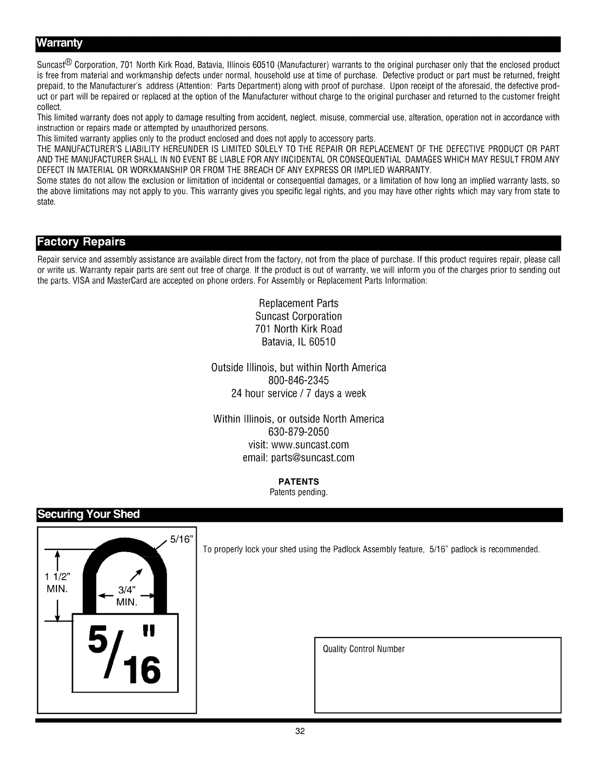
t
1 1/2"
MIN.
I!
16
16"
To properly lock your shed using the Padlock Assembly feature, 5/16" padlock is recommended.
Quality Control Number
32
