SUNVALLEYTEK VA-HS002A IPC for Home Cam User Manual VA HS002 20181218 v3 0
SUNVALLEYTEK INTERNATIONAL, INC. IPC for Home Cam VA HS002 20181218 v3 0
15_VA-HS002 UserMan
VAVA Home Cam
Quick Start Guide
VA-HS002
www.vava.com
E-mail: support@vava.com
Tel: 1-888-456-8468 (Monday-Friday: 9:00 – 17:00 PST)
Address: 46724 Lakeview Blvd, Fremont, CA 94538
NORTH AMERICA
EUROPE
E-mail:
support.uk@vava.com(UK)
support.de@vava.com(DE)
support.fr@vava.com(FR)
support.es@vava.com(ES)
support.it@vava.com(IT)
EU Importer: ZBT International Trading GmbH, Halstenbeker Weg 98C,
25462 Rellingen, Deutschland
ASIA PACIFIC
E-mail: support.jp@vava.com(JP)
JP Importer: 株式会社SUNVALLEYJAPAN
Address: 〒104-0032東京都中央区八丁堀3丁目18-6PMO京橋東9F
MANUFACTURER
Shenzhen NearbyExpress Technology Development Co.,Ltd.
Address: 333 Bulong Road, Shenzhen, China, 518129
MADE IN CHINA
VAVA HOME CAM
Quick Start Guide
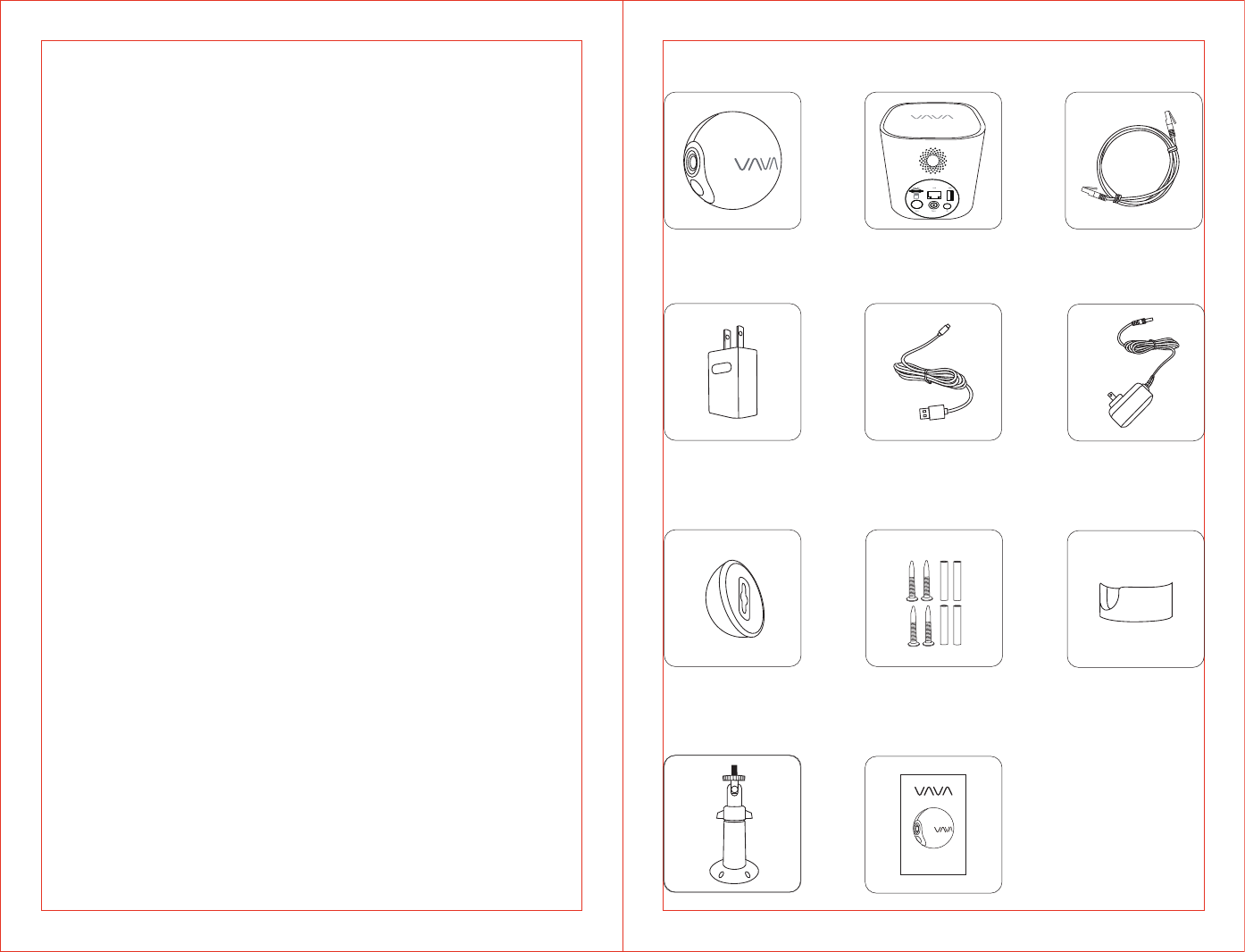
What’s in the Box
Camera Ethernet CableBase Station
Mounting Screws
& Anchors
Desktop Mount
Magnetic Wall
Mount
Stand Mount Quick Start Guide
Camera Power
Adapter
USB Charging Cable Base Station
Power Adapter
01/02
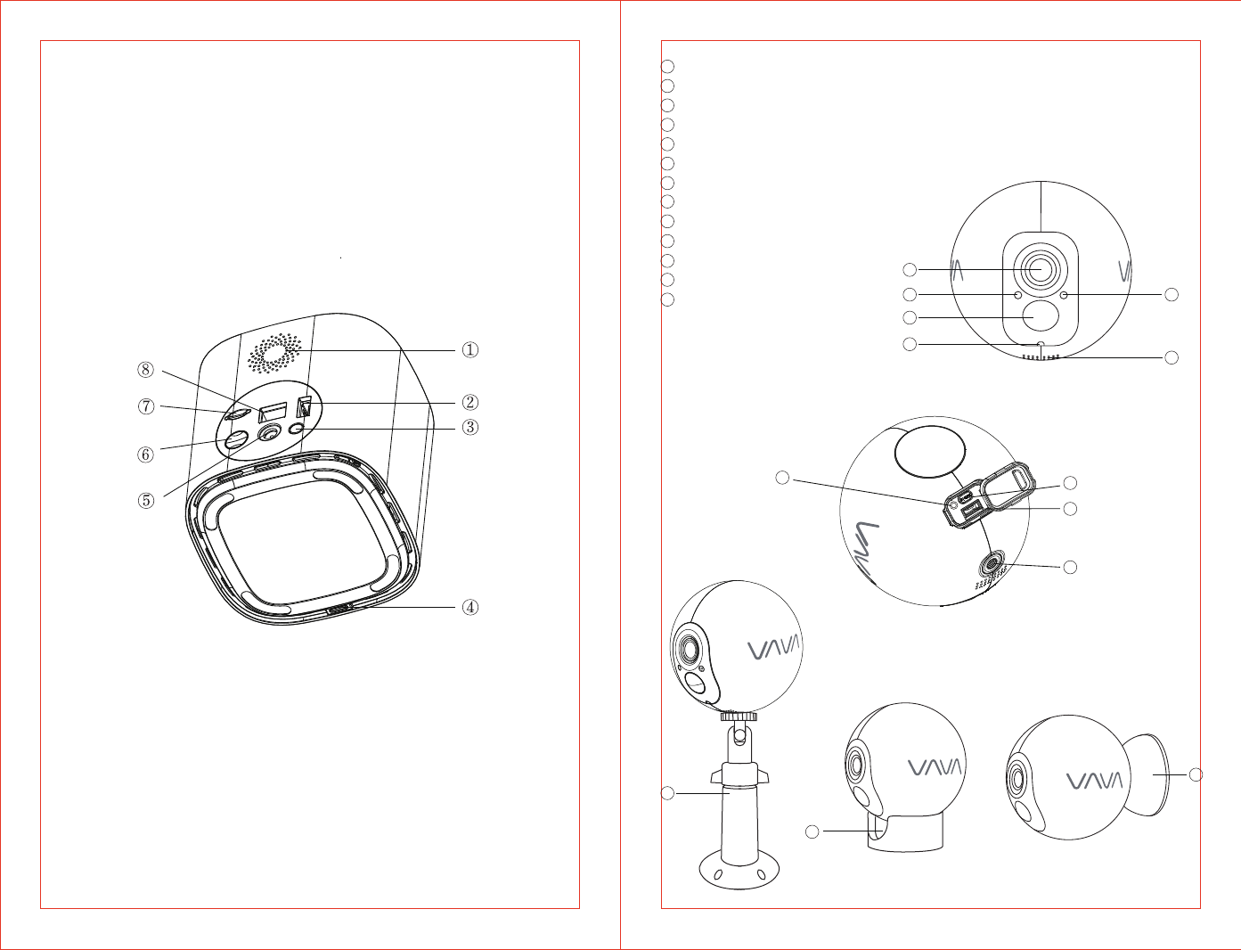
Product Diagram
Base Station
①
②
③
④
⑤
⑥
⑦
⑧
Speaker
USB Port
Reset Button
LED Indicator
Power Port
Sync Button
Micro SD Card Slot
Ethernet Port
Camera
Lens
Light Sensor
PIR Motion Sensor
LED Indicator
Microphone
Speaker
Reset Button
Sync Button
Micro USB Charging Port
Mount Port
Magnetic Mount
Desktop Mount
Stand Mount
1
2
3
4
5
6
7
8
9
10
11
12
13
1
2
3
4
5
6
78
9
10
11
12
13
03/04
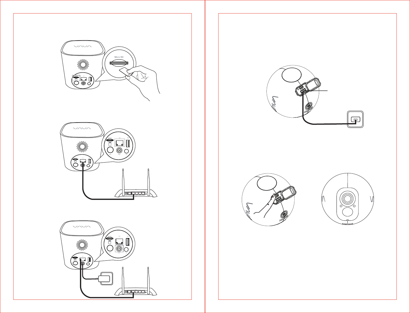
1. Insert the TF card into the base station.
Get Started
Connect Your Base Station
2. Connect the base station to your router with the included Ethernet cable.
3. Connect the base station to a power source.
Note:
The LED indicator on the base station will keep flashing red when connecting
to the internet and turn solid white once successfully connected.
Charge the Camera
Please fully charge the camera before use to ensure longer working time.
Micro USB
Charging Port
Download the APP
Before using the device, please download the “VAVA Home” app on your
smartphone or tablet from the App Store or Google Play.
Please follow the instructions in the app to register / log in your account, add
the base station / camera.
Turn on the Camera
Press the Sync Button on the camera to turn it on. The LED indicator on the
camera will stay solid on for 5 seconds then turn off.
05/06
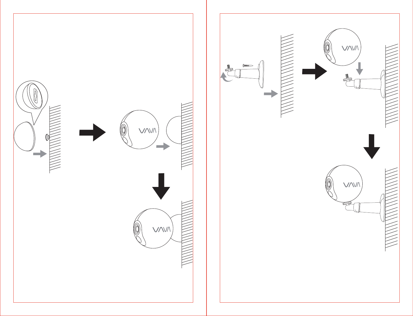
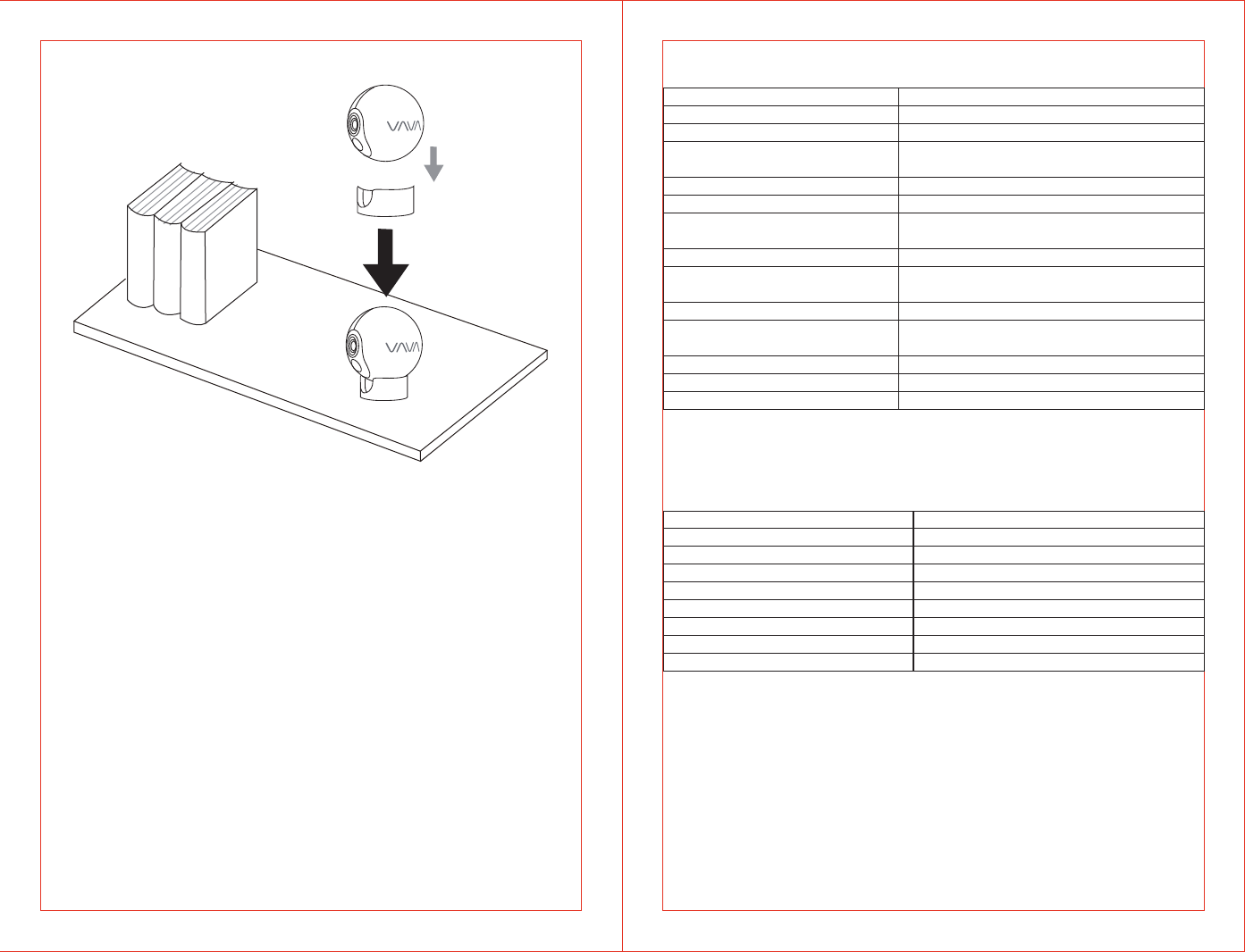
Mount Your Camera
Install the camera on a shelf, wall, or any flat surface with our complete
mounting set.
On the wall
Fasten the mounting screws into the wall and attach the magnetic mount.
When you are mounting the camera to drywall, be sure to use the plastic
anchors.
On the Stand Mount
07/08
On a desktop or a shelf Specifications
Camera
Lens
Sensor
Resolution
Microphone
Speaker
Battery
Power Consumption in Standby
Mode
Adapter Power
Weather Proof
Dimensions
Working Environment
140°Wide Angle, f / 2.2
IMX323, 1 / 2.9 inch
1080p
2 x 850nm Infrared Light, Effective Range:
8m / 26.2ft
Built-In
1.5W, 8Ω
Detection Angle 110°, Effective Range:
7m / 23.0ft
2500mAh Polymer Battery, 7.68V
5V / 1.8A
2.4G Wi-Fi, Effective Range 60m / 197.0ft
(empty space)
IP66
80.4 x 80.4 x 80.4 mm / 3.2 x 3.2 x 3.2 in
-20°C to 50°C / -4F-122F, RH≤95%
Base Station
Speaker
Micro SD Card Memory
Internet Connection
Effective Range
Max Number of Connected Cameras
Adapter Power
USB Output
Dimensions
Working Environment
2W, 8Ω
Up to 128G
Wired Connection
60m / 197.0ft (empty space)
4
12V / 1.5A Max
5V / 2A
95 x 95 x 95 mm / 3.7 x 3.7 x 3.7 in
-20°C to 50°C / -4F-122F, RH≤95%
Night View
PIR Detection
Internet
≤4mW
09/10
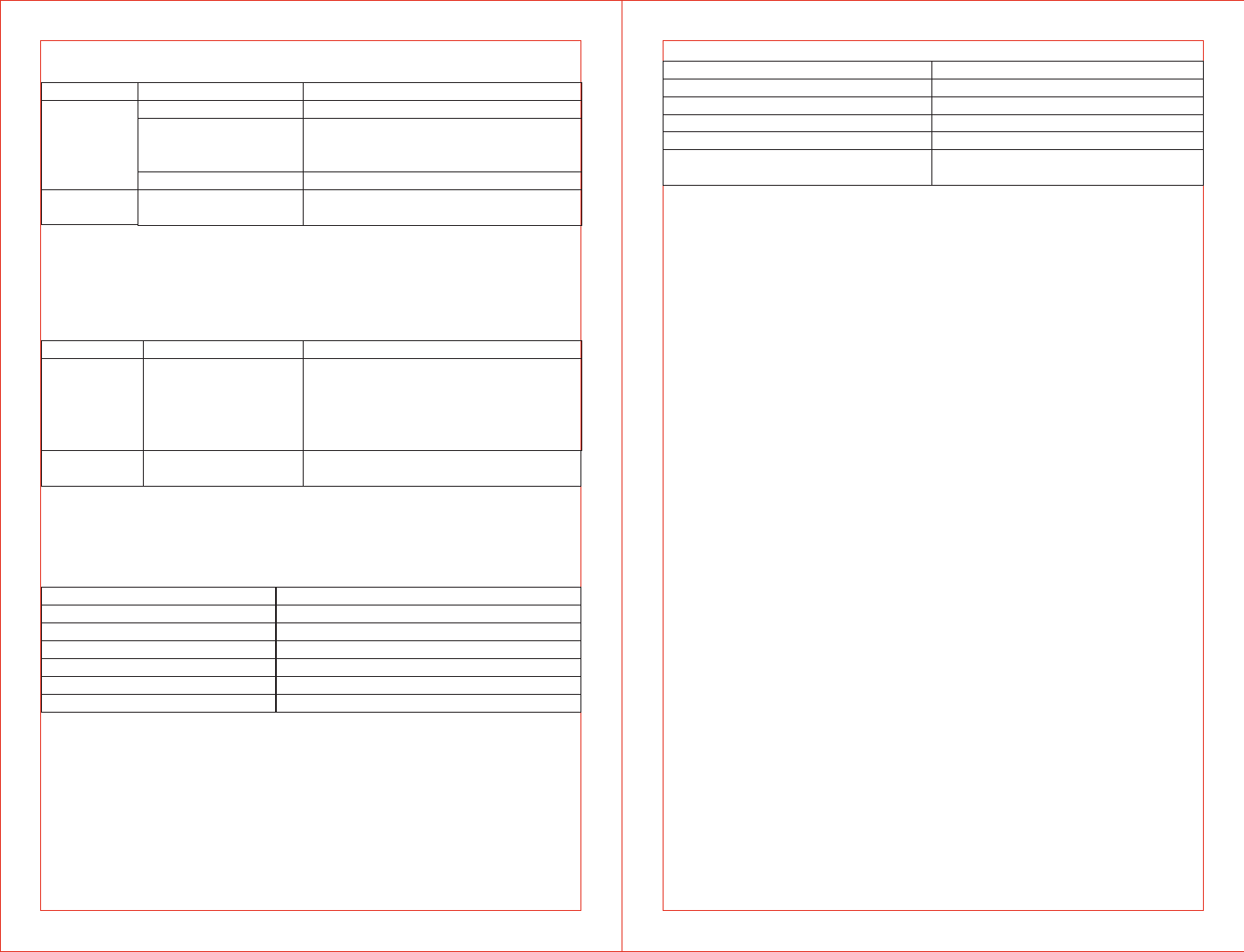
Button Controls
Camera
Button
Reset
Button
Operation
Press once
Press and hold for 5 seconds to enter
pairing mode with the LED indicator
flashing blue slowly
Press and hold for around 10 seconds
Press once to reboot the camera
without losing any data
Function
Turn on the camera
Turn off the camera
Note: The Sync Button is not functional during firmware upgrading.
Button Operation
Press and hold the Sync and Reset
Buttons at the same time until the
LED indicator flashes red and white
alternately to bring the base station
into pairing mode.
Function
Base Station
LED Indicator
Off
Flashes Blue Slowly
Flashes Blue Quickly
Flashes Red Slowly
Solid on in Red
Solid on in Red for 5s then off
Working Status
Sleep Mode/ Power Off
Pairing Mode
Paired Successfully
Charging
Fully Charged
Powering On
LED Indicator & Working Status
Camera
Base Station
LED Indicator
Solid On in Red and White
Solid On in White
Flashes Red
Flashes Red and White Alternately
Flashes Red and White at the
Same Time
Working Status
Powering On
Connected to Internet
No Internet
Pairing Mode
Caution
· Use the included power adapters only to charge the camera and the base
station within the permitted voltage range.
· Only the camera is waterproof. The base station and adapters are for
indoor use only.
· Make sure the internet is functional and fast for live data feed.
· Do not use the product at temperatures higher or lower than the specified
range.
· Do not use in environments with strong electromagnetic interferences or
near corrosive substances.
· The warranty does not cover defects and damages caused by misuse,
unauthorized dismantling, or natural hazards.
· The battery life varies according to the frequency of the triggers and the
video resolution settings.
· The PIR motion sensor can only detect motions within a certain ranges and
will not be activated by motions out of the range.
Sync Button Pair with the base
station
Reboot the camera
Sync Button
Reset Button
Add the Base station
Press and hold for 10 seconds
Restore to Factory Setting
Restore to factory
settings

11
FCC Radiation Exposure Statement:
This equipment complies with FCC radiation exposure limits set forth for an
uncontrolled environment. This equipment should be installed and operated
with minimum distance 20cm between the radiator & your body.
FCC STATEMENT:
This device complies with Part 15 of the FCC Rules. Operation is subject to the
following two conditions:
(1)This device may not cause harmful interference, and
(2)This device must accept any interference received, including interference
that may cause undesired operation.
Warning: Changes or modifications not expressly approved by the party
responsible for compliance could void the user's authority to operate the
equipment.
NOTE: This equipment has been tested and found to comply with the limits for
a Class B digital device, pursuant to Part 15 of the FCC Rules. These limits are
designed to provide reasonable protection against harmful interference in a
residential installation. This equipment generates uses and can radiate radio
frequency energy and, if not installed and used in accordance with the
instructions, may cause harmful interference to radio communications.
However, there is no guarantee that interference will not occur in a particular
installation. If this equipment does cause harmful interference to radio or
television reception, which can be determined by turning the equipment off
and on, the user is encouraged to try to correct the interference by one or
more of the following measures:
• Reorient or relocate the receiving antenna.
• Increase the separation between the equipment and receiver.
• Connect the equipment into an outlet on a circuit different from that to
which the receiver is connected.
• Consult the dealer or an experienced radio/TV technician for help