SVOA Public EXPLORER COMPUTER User Manual A4D9E8C1D7CD464343
SVOA Public Co.,Ltd. COMPUTER A4D9E8C1D7CD464343
USERS MANUAL
MANUAL
Professional
Contents
Notices................................................................................................ A
Safety information.............................................................................. B
Specification summary....................................................................... C
About this guide................................................................................. D
Chapter 1: Product introduction
1.1 Central Processing Unit(CPU)..................................................... 1
1.1.1 Overview............................................................................ 1
1.1.2 Installing the CPU............................................................. 2
1.2 System memory............................................................................ 3
1.2.1 DIMM sockets location..................................................... 3
1.2.2 Memory configurations..................................................... 3
1.2.3 Installing a DIMM............................................................ 4
1.3 Expansion slots............................................................................. 5
1.3.1 PCI slots............................................................................ 5
1.3.2 AGP slot............................................................................ 5
1.4 Jumpers.......................................................................................... 6
1.5 Connectors..................................................................................... 8
1.5.1 Rear panel connectors....................................................... 8
1.5.2 Internal connectors............................................................ 9

BA
Notices
Federal communications Commission Statement
This device complies with FCC Rules part 15. Operation is subject to the
following two conditions:
· This device may not cause harmful interference, and
· This device must accept any interference received including interference
that may cause undesired operation.
This equipment has been tested and found to comply with the limits for a
Class B digital device, pursuant to Part 15 of the FCC Rules. These limits
are designed to provide reasonable protection against harmful interference
in a residential installation. This equipment generates, uses and can radiate
radio frequency energy and, if not installed and used in accordance with
manufacturer’s instructions, may cause harmful interference to radio
communications. However, there is no guarantee that interference will not
occur in a particular installation. If this equipment does cause harmful
interference to radio or television reception, which can be determined by
turning the equipment off and on, the user is encouraged to try to correct the
interference by one or more of the following measures:
· Reorient or relocate the receiving antenna.
· increase the separation between the equipment and receiver.
· Connect the equipment to an outlet on a circuit different from that to
which the receiver is connected.
· Consult the dealer or an experienced radio/TV technician for help.
The use of shielded cables for connection of the monitor to the
graphics card is required to assure compliance with FCC regulations.
Changes or modifications to this unit not expressly approved by the
Party responsible for compliance could void the user’s authority to
Operate this equipment
Canadian Department of Communications Statement
This digital apparatus does not exceed the Class B limits for radio noise
emissions from digital apparatus set out in the Radio Interference
Regulations of the Canadian Department of Communications.
This class B digital apparatus complies with Canadian ICES-003.
Safety information
Electrical safety
•To prevent electrical shock hazard, disconnect the power cable from
the electrical outlet before relocating the system.
•When adding or removing devices to or from the system, ensure that
the power cables for the devices are unplugged before the signal
cables are connected. If Possible, disconnect all power cables from the
existing system before you add a device.
•Before connecting or removing signal cables from the motherboard,
ensure that all power cables are unplugged.
•Seek professional assistance before using an adapter or extension
cord. These devices could interrupt the grounding circuit.
•Make sure that your power supply is set to the correct voltage in your
area. If you are not sure about the voltage of the electrical outlet you
are using, contact your local power company.
•If the power supply is broken, do not try to fix it by yourself. Contact a
qualified service technician or your retailer.
Operation safety
•Before installing the motherboard and adding devices on it, carefully
read all the manuals that came with the package.
•Before using the product, make sure all cables are correctly connected
and the power cables are not damaged. If you detect any damage,
contact your dealer immediately.
•To avoid short circuits, keep paper clips, screws, and staples away from
connectors, slots, sockets and circuitry.
•Avoid dust, humidity, and temperature extremes. Do not place the
product in any area where it may become wet.
•Place the product on a stable surface.
•If you encounter technical problems with the product, contact a
qualified service technician or your retailer.
C D
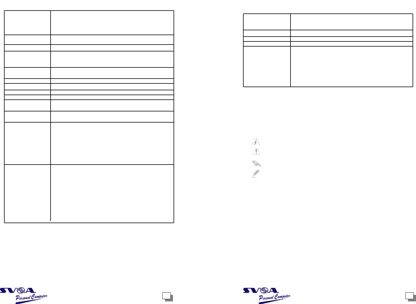
specification summary*
CPU Socket 478 for Intel Pentium 4 Northwood/Willamette
processor
Intel Hyper-Threading technology ready
New power design for next generation Intel Prescott CPU
Chipset SiS661 FX
SiS963L
Front Slide Bus (FSB) 800/533/400 MHz
Memory 2 x 184-pin DDR DIMM sockets for up to 2GB memory
Supports PC3200/2700/2100 unbuffered non-ECC DDR
DIMMs.
Expansion slots 1 x AGP 8x/4x (1.5V only)
3 x PCI
VGA SiS Real 256E integrated graphics
Storage 2 x Ultra ATA 133, PLO Mode 0~4
Audio ADI AD1888 6-channel audio CODEC
LAN Integrated MAC with VIA 6103L 10/100 LAN PHY
Hardware monitoring Super I/O integrated monitoring of CPU/chassis fan rotation
and MB/CPU temperature
Special features Power loss restart
Digital audio via an S/SDIF out interface
Rear panel I/O 1 x Parallel port
1 x Serial port
1 x Video port
1 x PS/2 keyboard port
1 x PS/2 mouse port
1 x RJ-45 port
4 x USB 2.0/USB 1.1 ports
Line In/Line Out/Microphone ports
Internal I/O 1 x USB 2.0 connector for additional two USB ports
CPU and chassis fan connectors
20-pin/4-pin ATX 12V power connectors
CD/AUX audio connectors
S/PDIF out connector
Front panel audio connector
Panel connector
Speaker out connector
GAME/MIDI connector
Power LED connector**
(Continued on the next page.)
* Specifications are subject to change without notice.
** Present only on PGB versions 1.03 or later.
specification summary
BIOS features 2Mb Flash EEPROM, DMI, features, SM BIOS 2.3,
WfM 2.0, ASUS CrashFree BIOS, ASUS EZ Flash, and
ASUS C.P.U. (CPU Parameter Recall)
Industry standard PCI 2.2, USB 2.0/1.1
Manageability WOL/WOR by PME, Wake on USB KB/Mouse
From Factor Micro-ATX form factor: 9.6 in x 9.6 in (24.5 cm x 24.5 cm)
Support CD contents Device drivers
PC Probe
LiveUpdate
Screensaver
Adobe Acrobat Reader
Trend MicroTM PC-cillin 2002 anti-virus software
Microsoft DirectX 8.1
About this guide
Conventions used in this guide
To make sure that you perform certain tasks properly, take note of the
Following symbols used throughout this guide.
WARNING: Information to prevent injury to yourself when trying
to complete a task.
CAUTION: Information to prevent damage to the components
when trying to complete a task.
IMPORTANT: Information that you MUST follow to complete a
task.
NOTE: Tips and additional information to aid in completing a task.
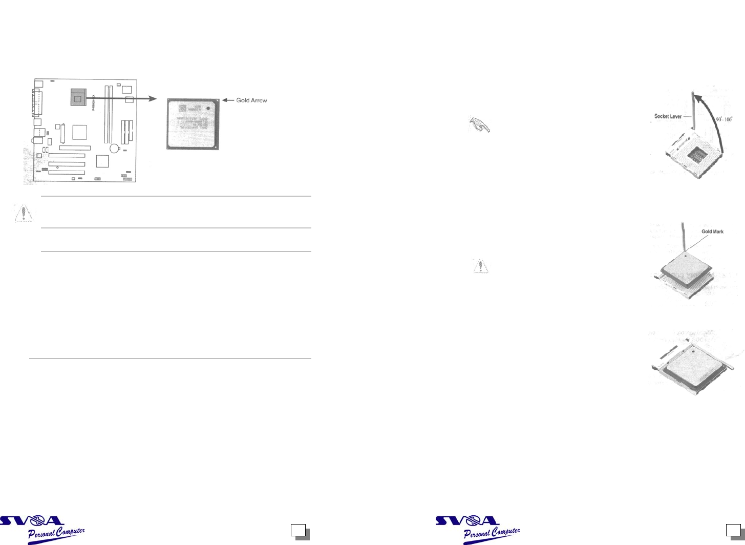
1.1.2 Installing the CPU
Follow these steps to install a CPU.
1. Locate the 478-pin ZIF socket on the motherboard.
2. Unlock the socket by pressing the
lever sideways, then lift it up to a 900-
1000 angle.
____________________________
Make sure that socket lever is
lifted up to 900-1000 angle,
otherwise the CPU does not fit in
completely.
___________________________
3. Position the CPU above the socket
such that its marked corner matches
the base of the socket lever.
4. Carefully insert the CPU into the
socket until it fits in place.
____________________________
The CPU fits only in one correct
orientation. DO NOT force the
CPU into the socket to prevent
bending the pins and damaging
the CPU!
____________________________
5. When the CPU is in place, push down
the socket level to secure the CPU.
The level clicks on the side tab to
indicate that it is locked.
6. Install a CPU heatsink and fan
following the instructions that came
with the heatsink package.
7. Connect the CPU fan cable to the
CPU_Fan1 connector on the
Motherboard.
1.1 Central Processing Unit (CPU)
1.1.1 Overview
The Intel Pentium 4 processor has a gold triangular mark on one corner. This
Mark indicates the processor Pin 1 that should match a specific corner of the CPU
socket
Incorrect installation of the CPR into the socket may bend the pins and
Severely damage the CPU!
Note on Intel Hyper-Threading Technology
1. Hyper-Threading Technology is supported under Window XP and Linux
2.4.x (kernel) and later versions only. Under Linux, use the Hyper-
Threading compliler to compile the code. If you are using any other operat-
ing systems, disable the Hyper-Threading Technology item in BIOS to en-
sure system stability and performance.
2. It is recommended that you install WinXP Service Pack 1.
3. Make sure to enable the Hyper-Threading Technology item in BIOS before
Installing a supported operating system.
4.For more information on Hyper-Threading Technology, visit
www.intel.com/Info/hyperthreading.
1 2
1.2 System memory
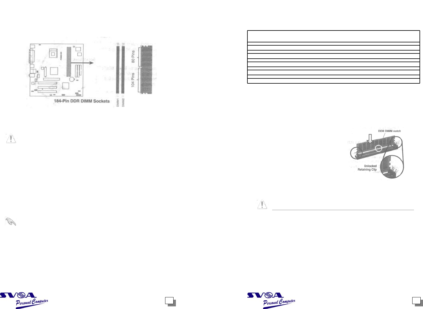
1.2.1 DIMM sockets location
The following figure illustrates the location of the DDR DIMM sockets.
___________________________________
Make sure to unplug the power supply before adding or removing DIMMs or
other system components. Failure to do so may cause severe damage to both
the motherboard and the components.
When installing long AGP cards, it is recommended to install the memory
modules first.Long AGP cards, when installed, nay interfere with the memory
sockets.
_________________________________________________________
1.2.2 Memory configurations
You may install 64MB, 128MB, 256MB, 512MB, and 1 GB DDR DIMMs into the
DIMM sockets.
_______________________________________________________________
Obtain DDR DIMMs only from qualified vendors. Refer to the
Qualified DDR400 vendors list next page. Visit for the Latest DDR
Qualified Vendors List.
__________________________________________________________
43
Table 1 Qualified DDR400 vendors list
This table lists the memory modules that have been tested and qualified for use
with this motherboard.
Size Vendor Part Number Chip Brand Side/s* Chip Number
512MB MICRON MT16VDOT6464AG-40B4 MICRON DS MT46V32M8TG-5BC
512MB CENTURY DXV2S8SSCCE3K27E SAMSUNG DS K4H560838E-TCCC
256MB CENTURY DXV6S8MC5BC3U27E MICRON SS MT46V32M8TG-5BC
256MB BRAIN POWER B6U808-256M-SAM-400 SAMSUNG SS K4H560838D-TCC4
256MB ATranscend TS32MLD64V4F3 MOSEL SS V58C2256804SAT5
256MB Apacer 77.10636.465 SAMSUNG SS K4H560838D-TCC4
256MB ATP AG32L64T8SQC4S SAMSUNG SS K4H560868D-TCC4
256MB NANYA NT256D64S88B1G-5T NANYA SS NT5DS32M8BT-5T
256MB MICRON MT8VDDT3264AG-40BC4 MICRON SS MT46V32M8TG-5BC
512MB elixir M2U25664DS8HB3G-5T elixir DS N2DS25680BT-5T
* Side/s:
DS-Double-sided
SS-Single-Sided
1.2.3 Installing a DIMM
Follow these steps to install a DIMM.
1. Unlock a DIMM socket by pressing
the retaining clips outward.
2. Align a DIMM on the socket such that
the notch on the DIMM matches the
break on the socket.
3. Firmly insert the DIMM into the socket
until the retaining clips snap back in
place and the DIMM is properly
seated.
_____________________________________________________________
A DDR DIMM is keyed with a notch so that it fits in only one direction. DO NOT
force a DMM into a socket to avoid damaging the DIMM.
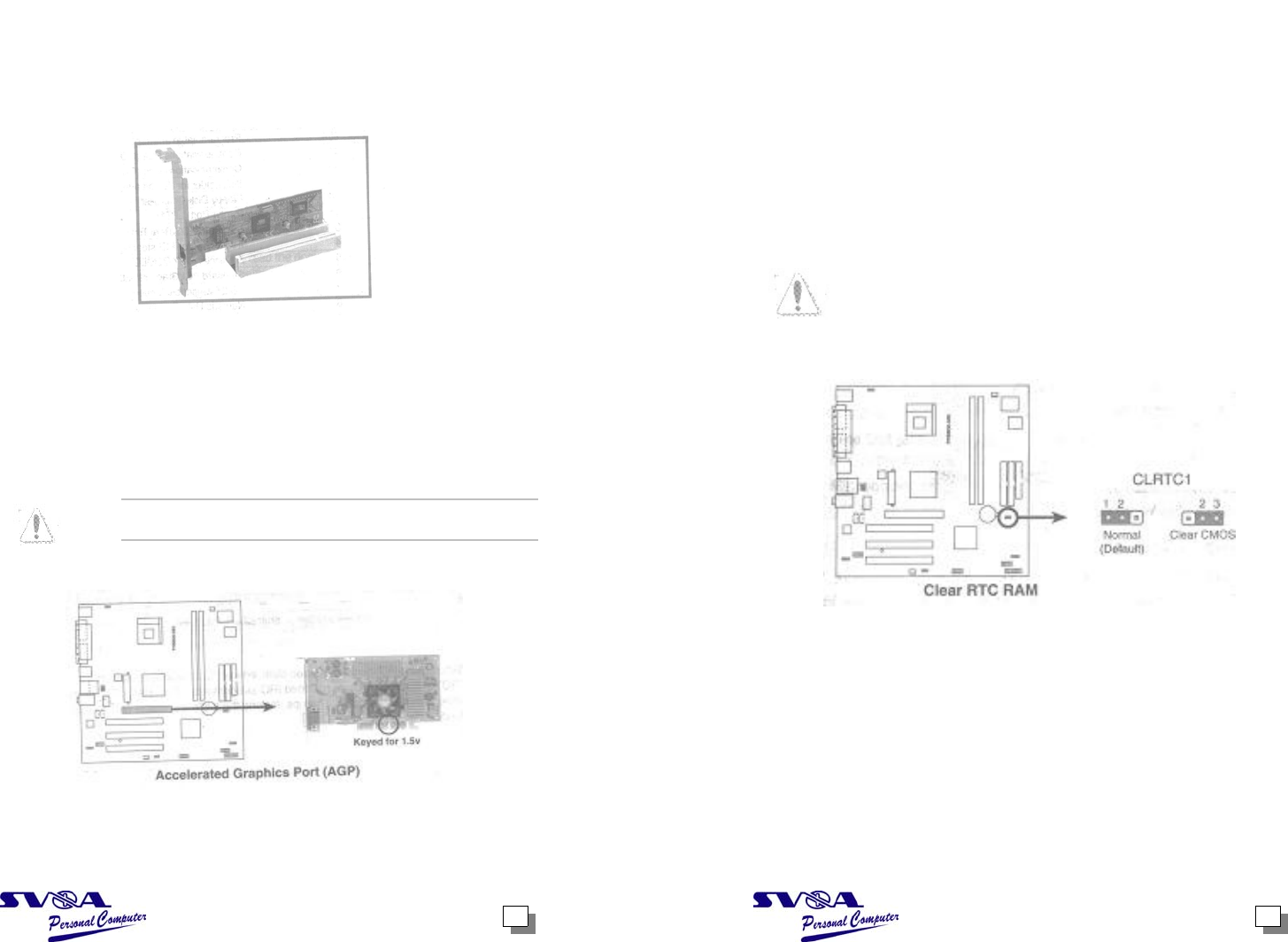
1.3 Expansion slots
1.3 PCI slots
The PCI slots support PCI cards such as a LAN card, SCSI card, USB card, and
other cards that comply with PCI specifications.
1.3.1 AGP slot
The Accelerated Graphics Port (AGP) slot that supports AGP 8X/4X (+1.5V) cards.
When you buy an AGP card, make sure that you ask for one with +1.5V
Note the notches on the card golden fingers to ensure that they fit the AGP slot on
the motherboard.
This motherboard does not support 3.3V AGP cards. Install only +1.5V AGP
cards.
5 6
1.4 Jumpers
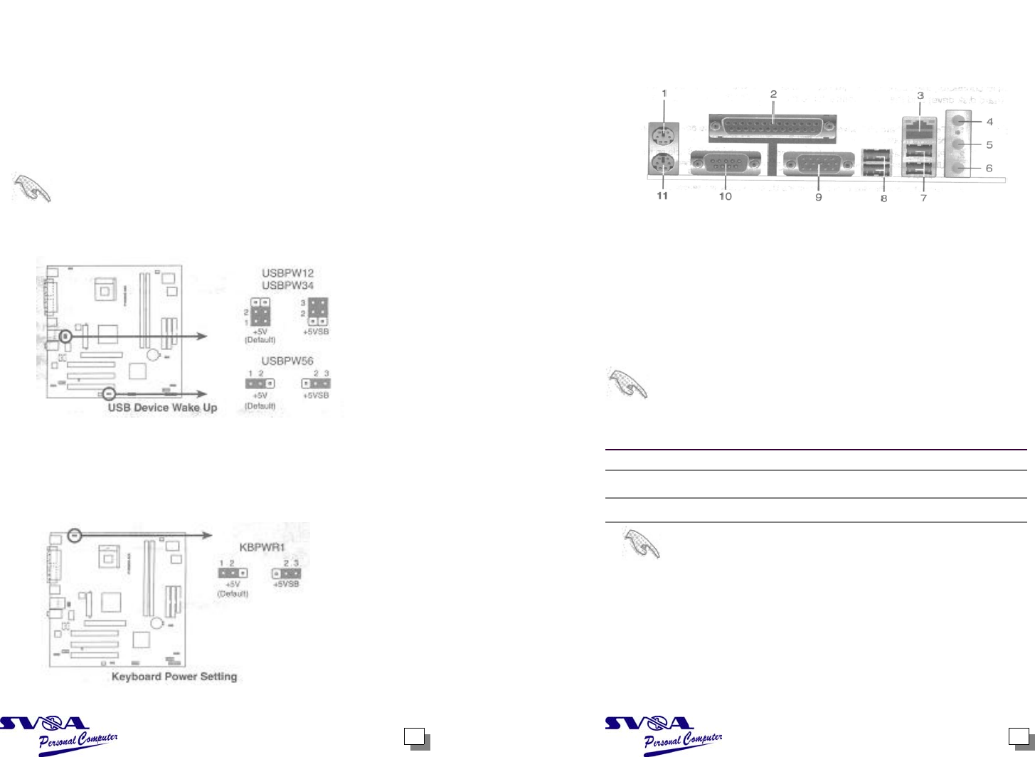
1. Clear RTC RAM (CLRTC1)
This jumper allows you to clear the Real Time Clock (RTC) RAM in CMOS.
You can clear the CMOS memory of date, time, and system setup parameters
by erasing the CMOS RTC RAM data. The RAM data in CMOS, that include
system setup information such as system passwords, is powered by the
onboard button cell battery.
To erase the RTC RAM:
1. Turn OFF the computer and unplug the power cord.
2. Move the jumper cap from pins 1-2 (default) to pins 2-3. Keep the cap on
pins 2-3 for about 5~10 seconds, then move the cap back to pins 1-2.
3. Plug the power cord and turn ON the computer.
4. Hold down the <Del> key during the boot process and enter BIOS setup to
re-enter data.
_________________________________________________________________
Except when clearing the RTC RAM, never remove the cap on CLRTC1 jumper
Default position. Removing the cap will cause system boot failure!
_________________________________________________________________
87
2. USB device wake-up (3-pin USBPW12, USBPW34, USBPW56)
Set these jumpers to +5V to wake up the computer from S1 sleep mode (CPU
stopped, DRAM refreshed, system running in low power mode) using the
connected USB devices. Set to +5VSB to from S3 sleep mode (no
power to CPU, DRAM in slow refresh, power supply in reduced power mode).
Both jumpers are set to pins 1-2 (+5V) by default because not all computers
have the appropriate power supply to support this feature.
The USBPW_12 and USBPW_34 jumpers are for the rear USB ports. The
USBPW_56 jumper is for the internal USB header that you can connect to the
Front USB ports.
________________________________________________________________
1. This feature requires a power supply that can provide an least 1 A on the
+5VSB lead when these jumpers are set to +5VSB. Otherwise, the system
would not power up.
2. The total current consumed must NOT exceed the power supply capability
( +5VSB) whether under normal condition or in sleep mode.
________________________________________________________________
3. Keyboard power (3-pin KBPWR1)
This jumper allows you to enable or disable the keyboard wake-up feature. Set
this jumper to pins 2-3 (+5VSB) if you wish to wake up the computer when you
press a key on the keyboard (the default is the Space Bar). This feature
requires an ATX power supply that can supply at least 1A on the +5VSB lead,
and a corresponding setting in the BIOS (see 2.5.5 “APM Configuration”).
1.5 Connectors
This section describes and illustrates the motherboard rear panel and internal
connectors.
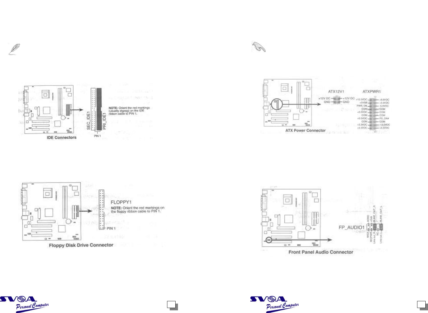
1.5.1 Rear panel connectors
1. PS/2 Mouse port. This green 6-pin connector is for a PS/2 mouse.
2. Parallel port. This 25-pin port connects a parallel printer, scanner, or other devices.
3. RJ-45 port. This port allows connection to a Local Area Network (LAN) through
a network hub.
4. Line In jack. This Line In (light blue) jack connects a tape player or other audio
sources. In 6-channel mode, the function of this jack becomes Bass/Center
5. Line Out jack. This Line Out (lime) jack connects a headphone or a speaker.
In 6-channel mode, the function of this jack becomes Front Speaker Out.
6. Microphone jack. This Mic (pink) jack connects a microphone. In 6-channel
Mode, the function of this jack becomes Rear Speaker Out.
_________________________________________________________________
The functions of the Line Out, Line In, and Microphone jacks change when you
Select the 6-channel audio configuration as shown in the following table.
______________________________________________________
Audio 2,4 or 6-channel configuration
Headphone/2-Speader 4-Speaker 6-Speaker
Light Blue Line In Line In Bass/Center
Lime Line Out Front Speaker Out Front Speaker Out
Pink Mic In Rear Speaker Out Rear Speaker Out
Windows 98SE only supports 2-channel speaker configuration.
7. USB 2.0 ports 1 and 2. These tow 4-pin Universal Serial Bus (USB) ports are
Available for connecting USB 2.0 devices.
8. USB 2.0 ports 3 and 4. These tow 4-pin Universal Serial Bus (USB) ports are
Available for connecting USB 2.0 devices.
9. VGA port. This port connects a VGA compatible monitor.
10. Serial port. This 9-pin COM port is for pointing devices or other serial devices.
11. PS/2 keyboard port. This purple connector is for a PS/2 keyboard.
109
1.5.2 Internal connectors
1. IDE connectors (40-1 pin PRI_IDE1, SEC_IDE1)
This connector supports the provided Ultra ATA 133 IDE hard disk ribbon cable.
Connect the cable’s blue connector to the primary (recommended) or secondary
IDE connector, then connect the gray connector to the UltraATA 133 slave device
(hard disk drive) and the black connector to the UltraATA 133 master device.
___________________________________________________________________
1. Follow the hard disk drive documentation when setting the device in master
or slave mode.
2. Pin 20 on each IDE connector is removed to match the covered hole on the
Ultra ATA cable connector. This prevents incorrect orientation when you
connect the cables.
3. The hole near the blue connector on the Ultra ATA cable is intentional.
___________________________________________________________________
2. Floppy disk drive connector (34-1 pin FLOPPY1)
This connector supports the provided floppy drive ribbon cable. After
connecting one end to the motherboard, connect the other end to the floppy
drive. (Pin 5 is removed to prevent incorrect insertion when using ribbon cables
with pin 5 plug).
3. ATX power connectors (20-pin ATXPWR1, 4-pin ATX12V1)
These connectors connect to an ATX 12V power supply. The plugs from the
power supply are designed to fit these connectors in only one orientation. Find
the proper orientation and push down firmly until the connectors completely fit.
In addition to the 20-pin ATXPWR connector, this motherboard requires that
you connect the 4-pin ATX +12V power plug to provide sufficient power to the
CPU.
________________________________________________________________
Make sure that your ATX 12V power supply can provide 8A on the + 12V lead
and at least 1A on the +5-volt standby lead (+5VSB). The Minimum
recommended wattage is 230W, or 300W, or 300W for a fully configured
system. The system may become unstable and may experience difficulty
powering up if the power supply is inadequate.
________________________________________________________________
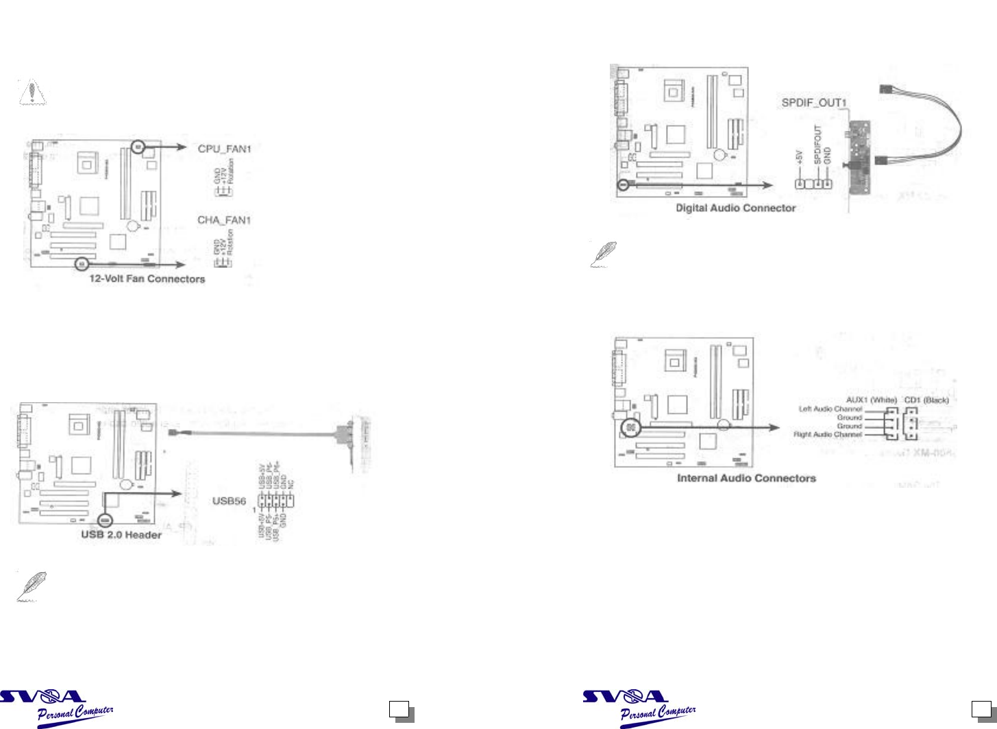
4. Front panel audio connector (10-1 pin FP_AUDIO 1)
This is an interface for the front panel cable that allows convenient connection
and control of audio devices.
Be default, the pins labeled LINE OUT_R/BLINE_OUT_R and the pins
LINE OUT_L/BLINE_OUT_L are shorted with jumper caps. Remove the caps
Only when you are connecting the front panel audio cable.
1211
5. CPU and chassis fan connectors (3-pin CPU_FAN1, CHA_FAN1)
The fan connectors support cooling fans of 350mA~740mA (8.88W max.)or a
total of 1A~2.22A (26.64W max.) at + 12V. Connect the fan cables to the fan
connectors on the motherboard, making sure that the black wire of each cable
matches the ground pin of the connector.
_________________________________________________________________
Do not forget to connect the fan cables to the fan connectors. Lack of sufficient
Air flow within the system may damage the motherboard components. These
Are not jumpers! DO NOT place jumper caps on the fan connectors!
_________________________________________________________________
6. USB header (10-1 pin USB 56)
If the USB port on the rear panel are inadequate, a USB header is available
for additional USB ports. Connect the USB cable of an optional USB 2.0
module to this header. You may install the USB module in the chassis front
panel. The nodule has two USB 2.0 ports for connecting next generation USB
peripherals such as high resolution cameras, scanners, and printers.
____________________________________________________________
The USB module is purchased separately.
____________________________________________________________
7. Digital audio connector (4-1 pin SPDIF_OUT1)
In addition to the S/PDIF Out port on the rear panel, an S/PFIF Out connector
is available for an S/PDIF audio module. Connect one end of the S/PDIF audio
cable this connector and the other end to the S/PDIF module.
______________________________________________________________
The S/PDIF module is purchased separately.
______________________________________________________________
8. Internal audio connectors (4-pin AUX1, CD1)
These connectors allow you to receive stereo audio input from sound sources
Such as a CD-ROM, TV tuner, or MPEG card.
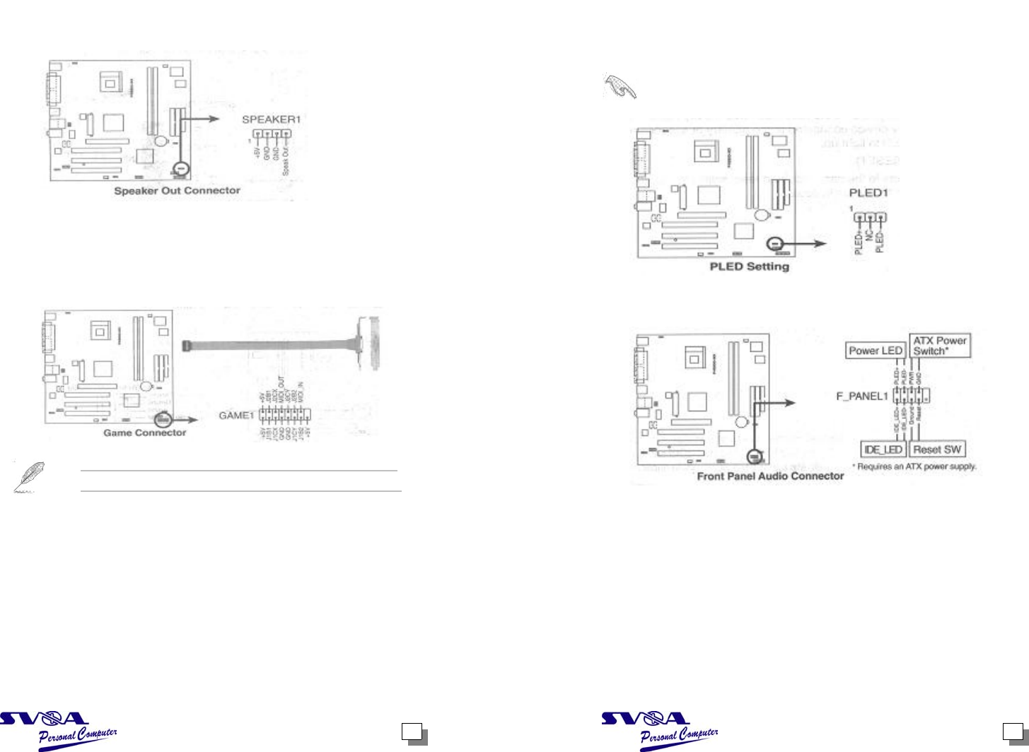
1413
9. Speaker out connector (4-pin SPEAK1)
This connector connects to the case-mounted speaker and allows you to hear
system beeps and warnings.
10. GAME/MIDI connector (16-1 pin GAME1)
This connector supports a GAME/MIDI module. Connect the GAME/MIDI cable
with yellow connector to the yellow header onboard. The GAME/MIDI port on
the module connects a joystick or a game pad for playing games, and MIDI
devices for playing or editing audio files.
The GAME module is purchased separately.
11. Power LED Lead (3-1 pin LED1)
This 3-1 pin connector is for the system power LED. Connect the 3-pin power
LED cable from the system chassis to this connector. The LED lights up when
you turn on the system power, and blinks when the system is in sleep mode.
________________________________________________________________
The power LED lead (PLED1) is present only on PCB versions 1.03 or later.
________________________________________________________________
12. System panel connector (10-1 pin F_PANEL1)
This connector accommodates several system front panel functions.
•Power LED Lead (2-pin PWR_LED)
This 2-pin connector connects to the system power LED. The LED lights up when
you turn on the system power, and blinks when the system is in sleep mode.
If your motherboard package comes with a 2-pin to 3-pin power LED converter,
Connect the 2-pin plug to this connector, and the other end to the 3-pin power
LED plug from the system chassis.

15
•Power Switch / Soft-Off Switch Lead (2-pin PWR_BTN)
This connector connects a switch that controls the system power. Pressing the
power switch turns the system between ON and SLEEP, or ON and SOFT
OFF, depending on the BIOS or OS settings. Pressing the power switch while
in the ON mode for more than 4 seconds turns the system OFF.
•IDE LED Lead (2-pin IDE_LED)
This 2-pin connector supplies power to the hard disk drive activity LED. The
read or write activities of any device connected to the primary or secondary
IDE connector cause this LED to light up.
•Reset Switch Lead (2-pin RESET)
This 2-pin connector connects to the case-mounted reset switch for rebooting
the system without turning off the system power.